Hi and thanks for using 2CarPros.
Have you checked or replaced cylinder 4 spark plug or coil?
https://www.2carpros.com/articles/how-to-change-spark-plugs
Here is a link to check for spark:
https://www.2carpros.com/articles/how-to-test-an-ignition-system
Also, can you provide the codes you get for the throttle body?
Considering the mileage, you may also want to check engine compression in cylinder 4. Here is a link showing how that is done.
https://www.2carpros.com/articles/how-to-test-engine-compression
Here are directions specific to this vehicle including specs:
Engine Compression Test
Tools Required
J 38722 Compression Tester
A compression pressure test of the engine cylinders determines the condition of the rings, the valves, and the head gasket.
1. Important: The battery must be at or near full charge. Do not block the throttle open.
Remove the air duct from the throttle control module.
2. Remove the ignition control modules.
3. Disable the fuel system.
4. Remove the spark plugs.
Picture 1
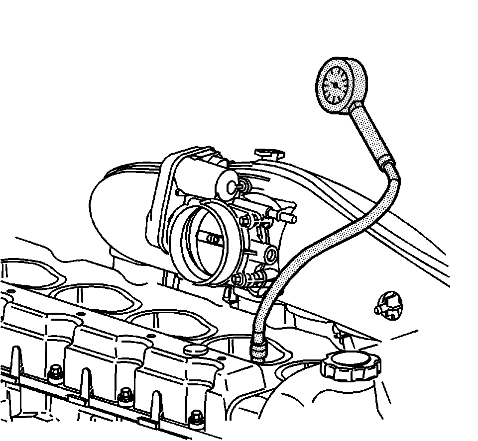
5. Measure the engine compression, using the following procedure:
1 Firmly install J 38722 to the spark plug hole.
2 Have an assistant crank the engine through at least four compression strokes in the testing cylinder.
3 Check and record the readings on J 38722 at each stroke.
4 Disconnect J 38722.
5 Repeat the compression test for each cylinder.
6. Record the compression readings from all of the cylinders. A normal reading should be approximately 1482 kPa (215 psi). The lowest reading should not be less than 70 percent of the highest reading.
7. The following are examples of the possible measurements:
^ When the compression measurement is normal, the compression builds up quickly and evenly to the specified compression on each cylinder.
^ When the compression is low on the first stroke and tends to build up on the following strokes, but does not reach the normal compression, or if the compression improves considerably with the addition of three squirts of oil, the piston rings may be the cause.
^ When the compression is low on the first stroke and does not build up in the following strokes, or the addition of oil does not affect the compression, the valves may be the cause.
^ When the compression is low on two adjacent cylinders, or coolant is present in the crankcase, the head gasket may be the cause.
8. Install the air duct to the throttle body.
9. Install the spark plugs.
10. Enable the fuel system.
11. Install the ignition control modules.
_______________________________
Do me a favor. Switch the coils between 4 and 1. See if the misfire moves.
IGNITION COIL(S) REPLACEMENT
REMOVAL PROCEDURE
1. Remove the air cleaner resonator and outlet duct.
Picture 2
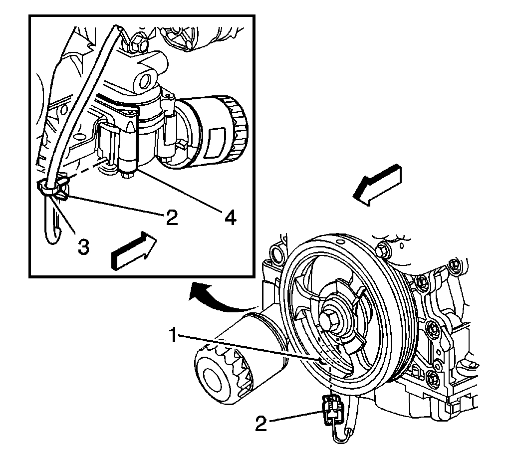
2. Disconnect the engine wiring harness electrical connector (2) from the oil pressure sensor (1).
3. Disconnect the engine wiring harness retainer (3) from the oil filter adapter (4).
Picture 3
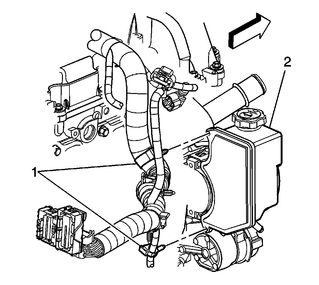
4. Disconnect the engine wiring harness retainers (1) from the power steering pump (2).
Picture 4
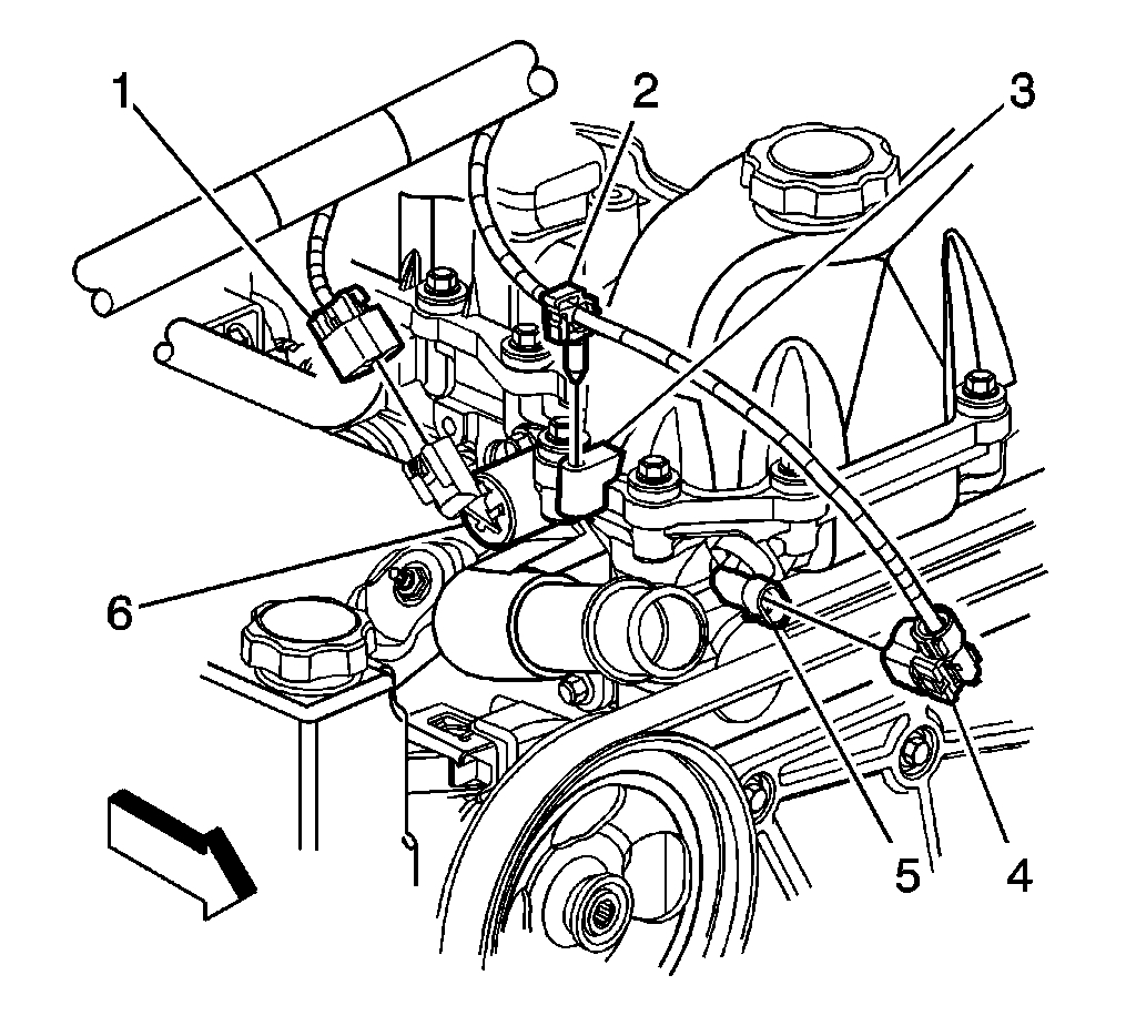
5. Disconnect the engine wiring harness electrical connectors (1, 4) from the following:
- The camshaft position (CMP) sensor (5)
- The camshaft position (CMP) actuator solenoid valve (6)
6. Disconnect the engine wiring harness retainer (2) from the camshaft cover (3).
Picture 5
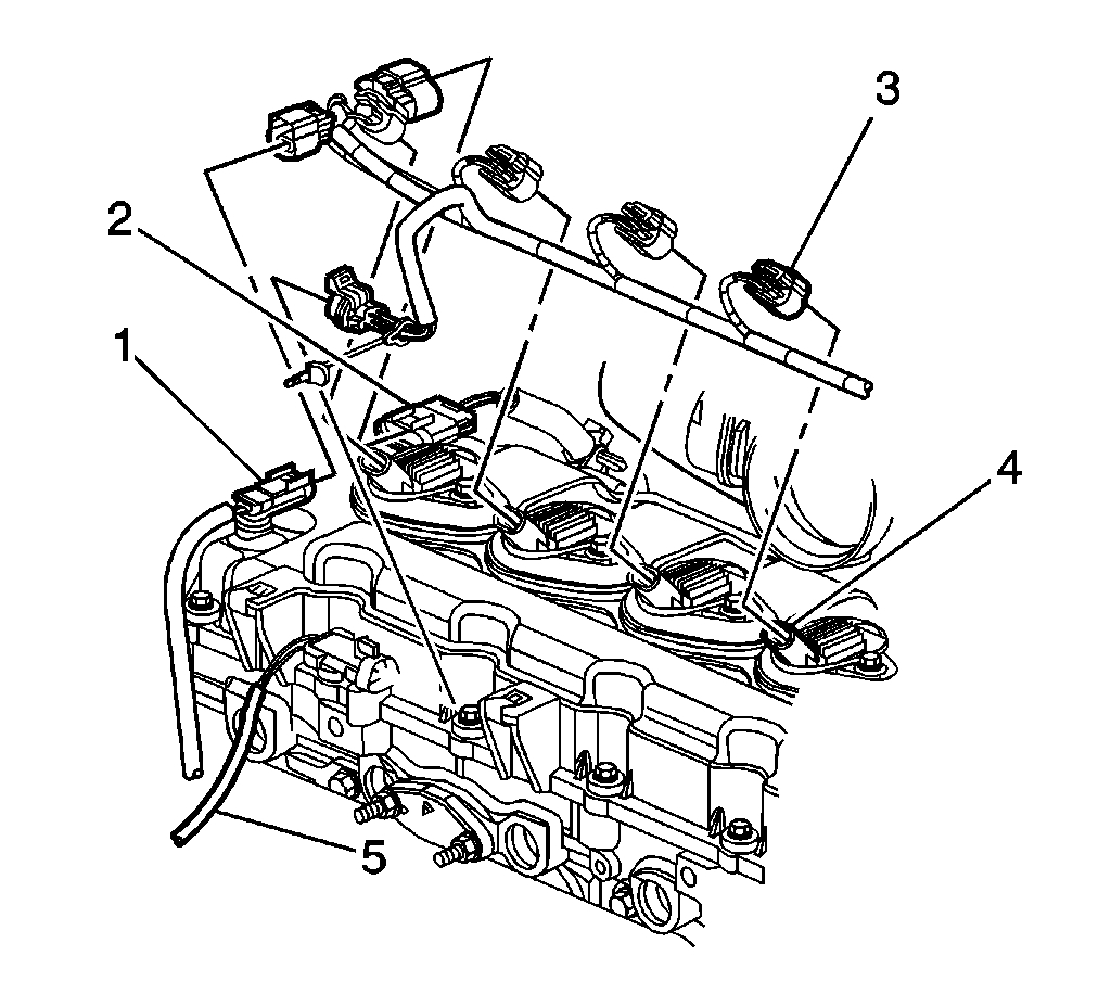
7. Disconnect the engine wiring harness electrical connectors from the following:
- The engine coolant temperature (ECT) sensor (1)
- The fuel injector harness (2)
- The ignition coils (4)
- The heated oxygen sensor (HO2S) (5)
Picture 6
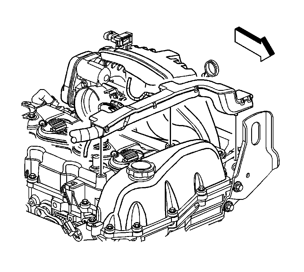
8. Carefully disengage the engine wiring harness conduit from the camshaft cover, and position aside.
Picture 7
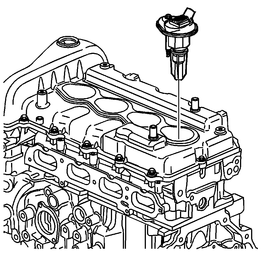
9. Remove the ignition coil bolts.
10. Remove the ignition coils from the camshaft cover.
INSTALLATION PROCEDURE
Picture 8
1. Install the ignition coils into the camshaft cover.
IMPORTANT: Ensure the ignition coil seals are properly seated to the camshaft cover.
2. Install the ignition coil bolts.
NOTE: Refer to Fastener Notice in Service Precautions.
Tighten the ignition coil bolts to 10 N.m (89 lb in).
Picture 9
3. Attach the engine wiring harness conduit to the camshaft cover.
Picture 10
4. Connect the engine wiring harness electrical connectors to the following:
- The ECT sensor (1)
- The fuel injector harness (2)
- The ignition coils (4)
- The HO2S (5)
Picture 11
5. Connect the engine wiring harness electrical connectors (1, 4) to the following:
- The CMP sensor (5)
- The CMP actuator solenoid valve (6)
6. Connect the engine wiring harness retainer (2) to the camshaft cover (3).
Picture 12
7. Connect the engine wiring harness retainers (1) to the power steering pump (2).
Picture 13
8. Connect the engine wiring harness electrical connector (2) to the oil pressure sensor (1).
9. Connect the engine wiring harness retainer (3) to the oil filter adapter (4).
10. Install the air cleaner resonator and outlet duct.
_____________________________________________________________________________
Let me know the codes you are getting and let me know if any of this helps. Also, let me know the results of the coil switch.
Take care,
Joe
Images (Click to enlarge)
Jan 18, 2019 at 8:29 PM