I don't believe these two model years will cross. As far as replacement, here are directions for removal and replacement.
NOTE: Ensure front wheels are in the straight ahead position before performing the following procedure.
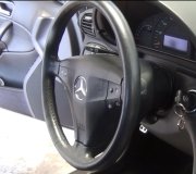
1. Disconnect battery ground cable, then remove steering wheel.
2. Remove left and right lower moldings from instrument panel by pulling up and snapping out of retainers. One right lower molding a screw will have to be removed in order to remove molding.
3. Remove instrument panel lower trim cover.
4. On models equipped with air bag, proceed as follows:
a. Remove air bag electrical connectors from main wiring at steering column bend bracket.
B. Using door trim removal tool, remove clock spring electrical connectors from bend bracket.
C. Using door trim removal tool, disconnect two wire harness clips from steering column.
D. Remove key warning buzzer contact and antitheft contact from ignition lock cylinder pocket of steering column tube flange.
E. Remove clock spring by pushing snap back at 6 o'clock position, then 3 o'clock position, then 12 o'clock position and remove from steering shaft.
5. Remove tilt lever by unscrewing it from column.
6. Rotate ignition switch to the RUN position, then using a 1/8 inch drift, depress lock cylinder retaining pin through access hole in lower shroud, then remove lock cylinder.
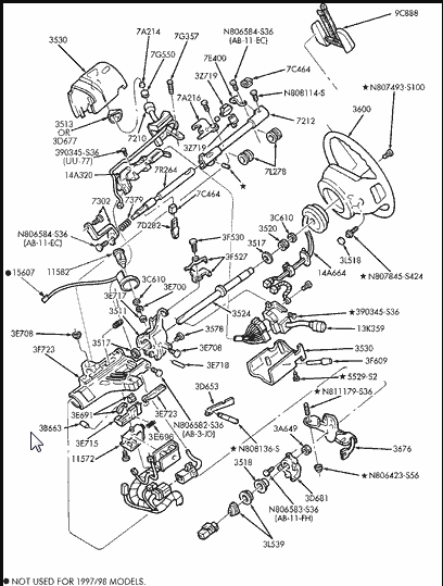
7. Remove four lower column shroud retaining screws, then column shrouds from steering column.
CAUTION: On vehicles equipped with E4OD transmission, a protective cover (such as a rag) must be placed between the shift lever and shroud opening during shroud removal. This will prevent damage to the shift lever shrink wrap.
8. Remove six instrument panel reinforcement brace retaining bolts, then reinforcement.
9. Disconnect PRND21 cable from actuator housing by removing one screw.
10. Disconnect PRND21 cable loop from shift tube hook.
11. Remove two multi-function switch retaining screws, then disconnect electrical connectors from switch.
12. Remove multi-function switch from column.
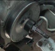
13. Remove pinch bolt from steering shaft flex coupling.
14. Disconnect shift cable from selector lever pivot.
15. Remove shift cable from shift cable bracket by pushing tab on cable in and sliding cable off bracket.
16. Disconnect ignition switch wiring by loosening bolt and removing connector.
NOTE: Bolt is part of connector and is not removable.
17. While supporting column assembly, remove four column assembly retaining nuts.
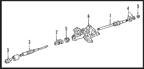
18. Disconnect collapsible intermediate shaft from U-joint at lower end of steering column, then remove steering column from vehicle.
INSTALLATION
1. Align column lower universal joint to lower shaft, then install one bolt. Torque retaining bolt to 30-42 ft lb.
2. Support column assembly to column support bracket, then install four retaining nuts and torque to 10-14 ft lb.
3. Install shift cable on shift cable bracket, then snap shift cable onto selector pivot ball.
4. Connect two multi-function switch electrical connectors, then position switch on column. Torque retaining screws to 18-27 in lb.
5. Connect all electrical connectors.
6. Connect PRND21 cable loop on shift selector hook, then install PRND21 cable bracket to actuator housing. Torque retaining screw to 5-8 ft lb.
7. Install instrument panel reinforcement brace, then five brace retaining bolts. Torque bolts to 10-14 ft lb.
8. Install upper and lower column shrouds, then lower instrument panel cover. On right lower molding installation, a screw will also have to be installed.
CAUTION: On vehicles equipped with E4OD transmission, a protective cover (such as a rag) must be placed between the shift lever and shroud opening during shroud installation. This will prevent damage to the shift lever shrink wrap.
9. Install lock cylinder assembly, then tilt lever.
10. Install air bag clockspring contact assembly. Torque retaining screws to 18-27 in lb.
11. Install steering wheel onto column shaft. Install a new bolt and torque to 23-33 ft lb.
12. On models less air bag, position horn cover to steering wheel and snap into place, then connect battery ground cable.
13. On models equipped with air bag, position air bag module to steering wheel. Install four retaining nuts and torque to 3-4 ft lb.
14. Verify air bag warning indicator, then drive vehicle for 10 miles to reestablish powertrain control module adaptive strategy.
_____________________________
I hope this helps. Let me know if you have other questions.
Take care,
Joe
Wednesday, January 20th, 2021 AT 6:02 PM