Good morning,
The 102 is based around the mass airflow sensor. Make sure the connector is tight and there are no air leaks to the throttle body.
https://www.2carpros.com/articles/stall-at-idle
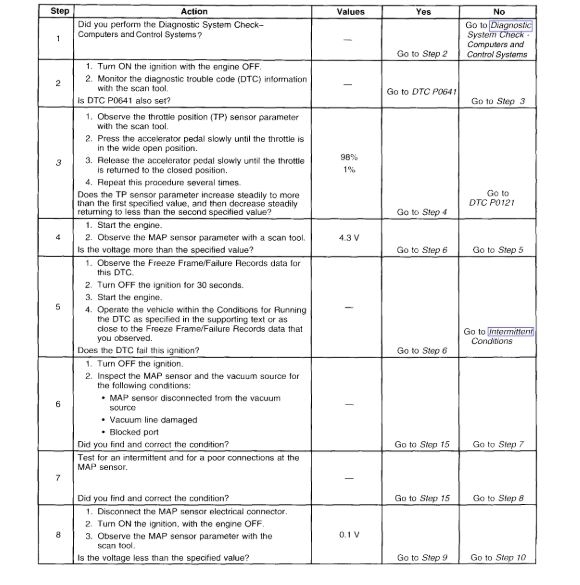
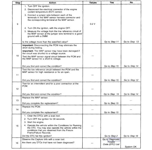
The 108 is for the MAP sensor. This could be a vacuum leak to the sensor. Make sure all the lines are in good shape and not cracked or broken.
The 620 is for PCM controlling the generator circuit of the alternator. I posted information below about that one.
The 300 is a misfire code. I attached a guide for you for that. Make sure the plugs and wires are in good condition and make sure the fuel pressure is correct.
https://www.2carpros.com/articles/engine-misfires-or-runs-rough
https://www.2carpros.com/articles/how-to-check-fuel-system-pressure-and-regulator
Roy
CIRCUIT DESCRIPTION
The powertrain control module (PCM) uses the generator turn on signal circuit to control the generator. A high side driver within the PCM allows the PCM to turn the generator ON and OFF. When generator operation is desired, the PCM sends a 5 volt signal to the voltage regulator via the generator turn ON signal circuit. This causes the voltage regulator to begin controlling the generator field circuit. Once the generator is enabled by the PCM, the voltage regulator controls generator output independently of the PCM. Under certain operating conditions, the PCM can turn OFF the generator by turning OFF the 5 voltsignal on the generator turn ON signal circuit. The PCM has fault detection circuitry which monitors the state of the generator turn ON signal circuit. If the fault detection circuit senses a voltage other than what is expected, this DTC will set. The voltage regulator also contains fault detection circuitry. If the regulator detects a problem, the regulator will ground the generator turn ON signal circuit, pulling the voltage low. This also causes the PCM to set the DTC.
When this DTC sets, the PCM sends a class 2 serial data message to the IPC illuminating the Charge indicator.
CONDITIONS FOR RUNNING THE DTC
The engine is running.
CONDITIONS FOR SETTING THE DTC
The generator turn ON signal circuit voltage is low while the PCM is commanding the generator ON.
The above condition is present for more than 30 seconds.
ACTION TAKEN WHEN THE DTC SETS
The PCM stores the DTC information into memory when the diagnostic runs and fails.
The malfunction indicator lamp (MIL) will not illuminate.
The PCM records the operating conditions at the time the diagnostic fails. The PCM stores this information in the Failure Records.
CONDITIONS FOR CLEARING THE MIL/DTC
A History DTC will clear after forty consecutive warm-up cycles, if no failures are reported by this or any other non-emission related diagnostic.
The current DTC will clear when the diagnostic runs and does not fail.
Use a scan tool in order to clear the MIL diagnostic trouble code.
Images (Click to make bigger)
Monday, October 21st, 2019 AT 5:56 AM