Hi and thanks for using 2CarPros.com.
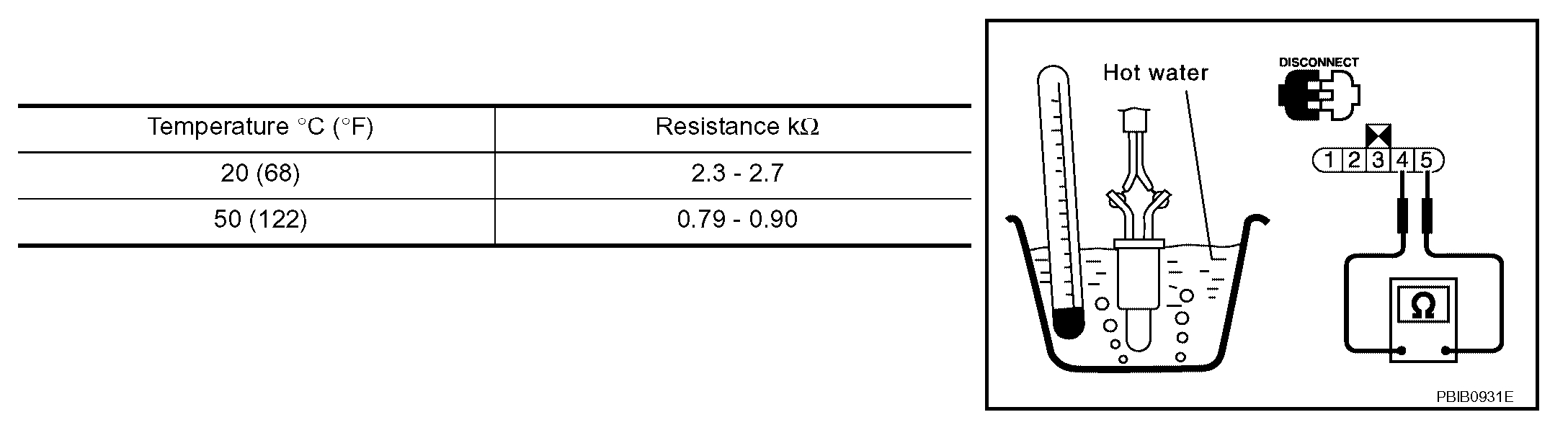
The components you mentioned are all replaced as a unit. The fuel level and temperature sensors are a single unit. I have attached picture for you to see. If you want to test the unit, see picture one. It indicates the amount of resistance that should be present based on temperature.
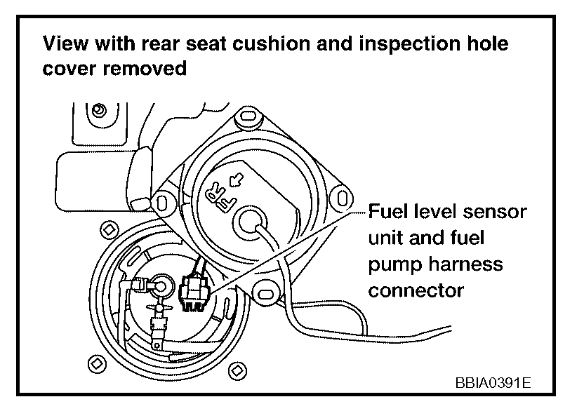
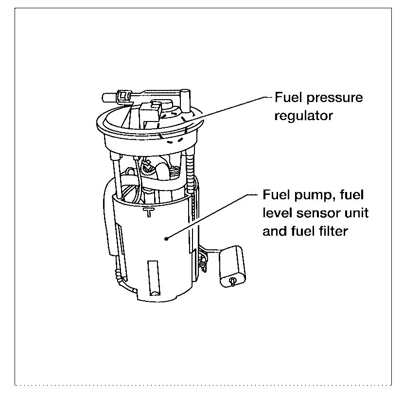
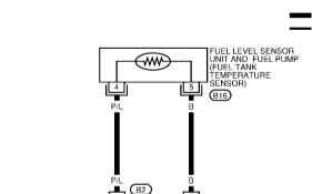
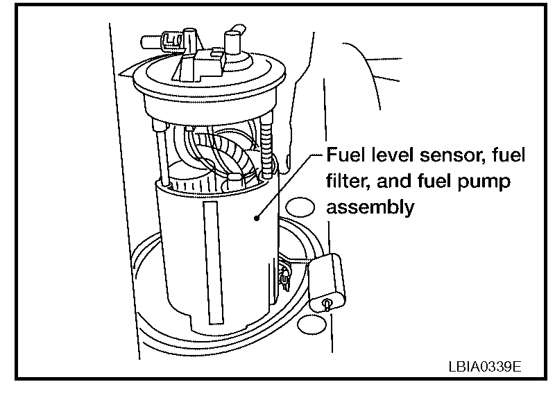
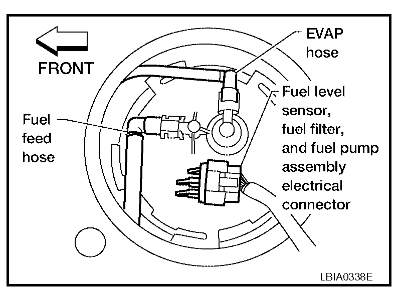
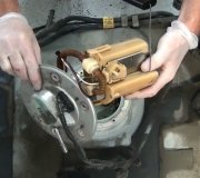
Picture 2 shows the top of the fuel pump sending unit from under the rear seat inspection cover. Picture 3 is a view of the entire pump assembly, and picture 4 shows how the temperature and level components are one unit.
Here is a link that shows in general how a pump is replaced. You are lucky because you can access it from in the vehicle (rear seat) and are not required to remove the tank.
https://www.2carpros.com/articles/how-to-replace-an-electric-fuel-pump
If you decide to replace the pump, here are the directions specific to your vehicle. Starting with picture 5, the remaining pics correlate with these directions.
________________________________
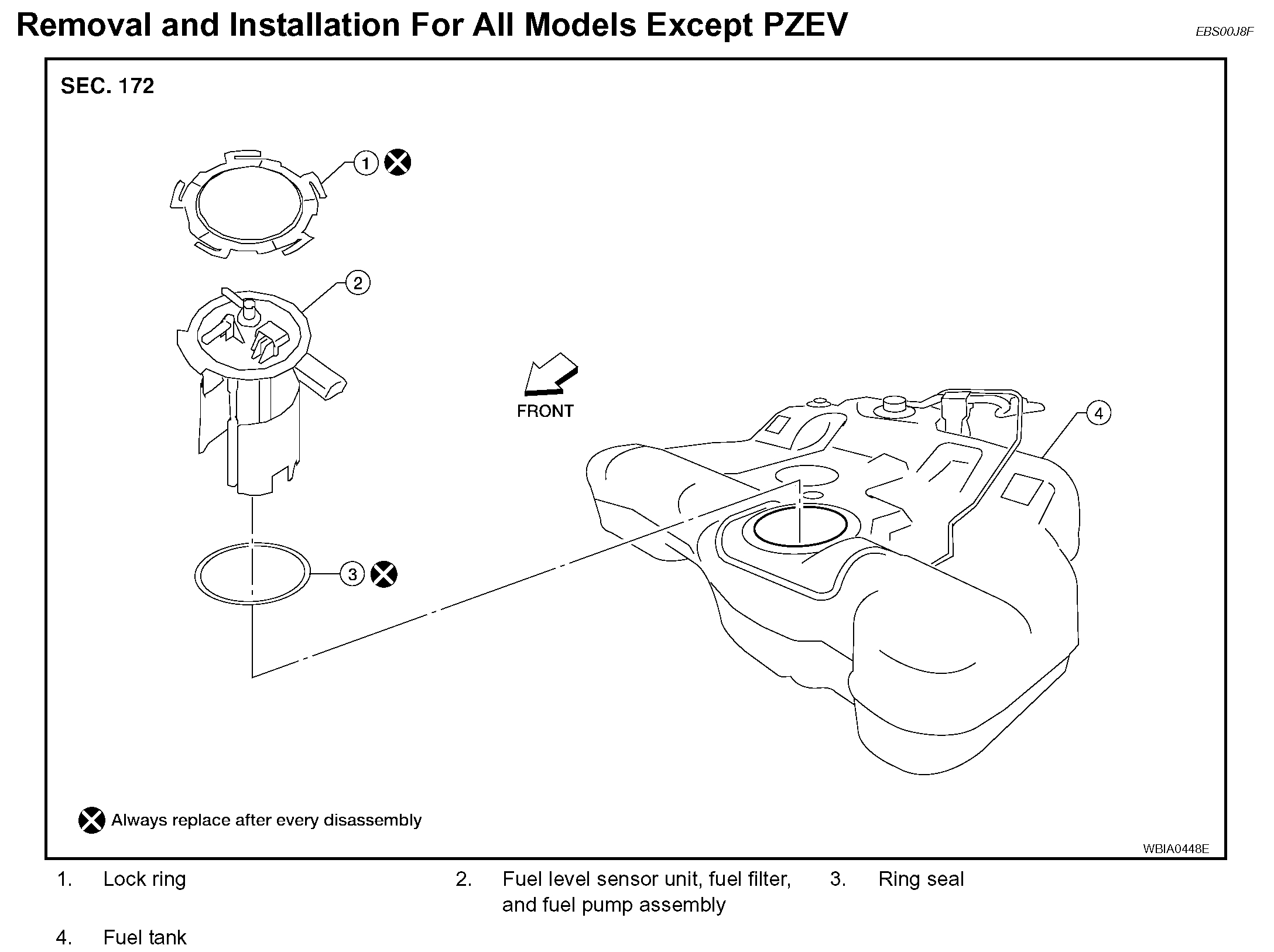
FUEL LEVEL SENSOR UNIT, FUEL FILTER AND FUEL PUMP ASSEMBLY
Removal and Installation For All Models Except PZEV
REMOVAL
WARNING:
Read "General Precautions" before working on the fuel system.
Refer to "General Precautions".
1. Unscrew the fuel filler cap to release the pressure inside the fuel tank.
2. Release the fuel pressure from the fuel lines. Refer to "FUEL PRESSURE RELEASE" (QR25DE), "FUEL PRESSURE RELEASE" (VQ35DE).
3. Disconnect the battery negative terminal.
4. Remove the rear seat bottom. Refer to "Removal and Installation".
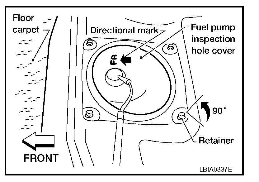
5. Turn the four retainers 90 ° in a clockwise direction and remove the fuel pump inspection hole cover.
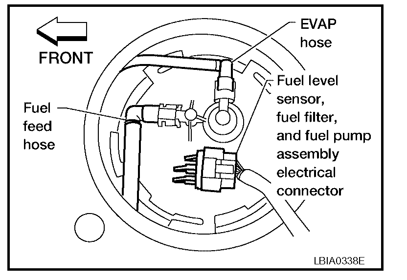
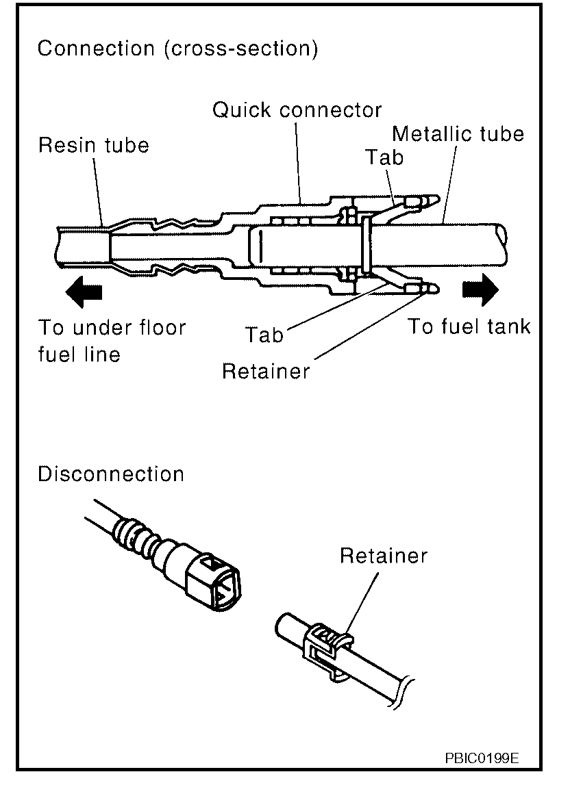
6. Disconnect the fuel level sensor, fuel filter, and fuel pump assembly electrical connector, EVAP hose quick connector, and the fuel feed hose quick connector from the fuel level sensor unit, fuel filter, and fuel pump assembly.
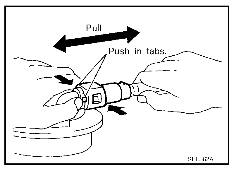
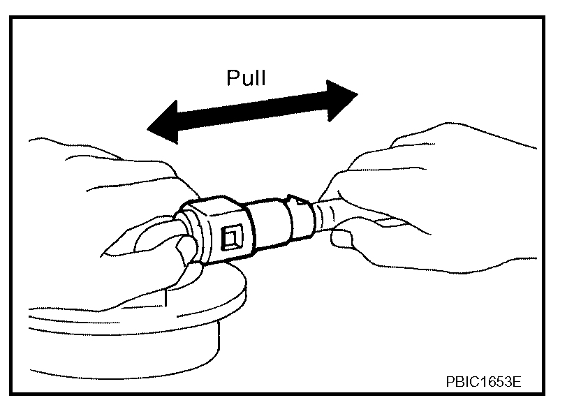
Remove the quick connector as follows:
- Hold the sides of the connector, push in tabs and pull out the tube.
- If the connector and the tube are stuck together, push and pull several times until they start to move. Then disconnect them by pulling.
CAUTION:
- The tube can be removed when the tabs are completely depressed. Do not twist it more than necessary.
- Do not use any tools to remove the quick connector.
- Keep the resin tube away from heat. Be especially careful when welding near the tube.
- Prevent acid liquid such as battery electrolyte, etc. from getting on the resin tube.
- Do not bend or twist the tube during installation and removal.
- Only when the tube is replaced, remove the remaining retainer on the tube or fuel level sensor, fuel filter, and fuel pump assembly.
- When the tube or fuel level sensor, fuel filter, and fuel pump assembly is replaced, also replace the retainer with a new one (green colored retainer).
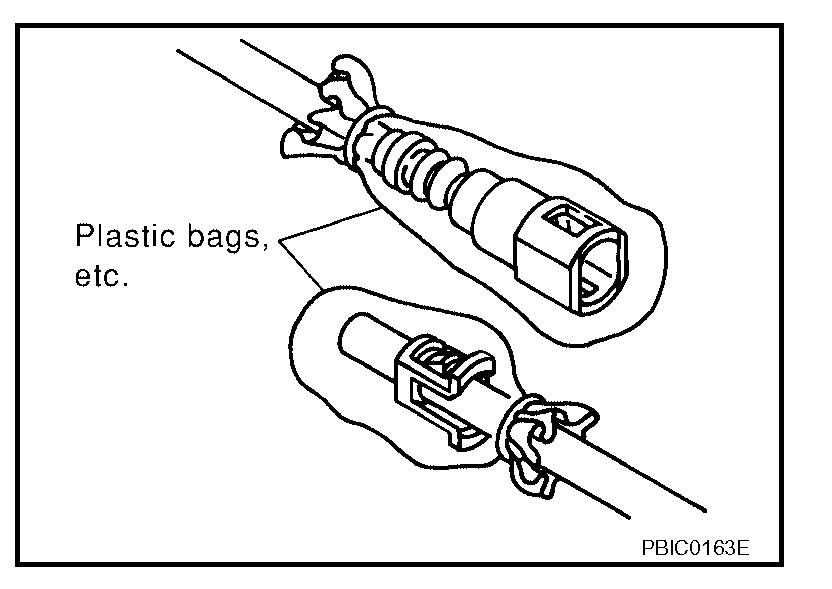
- To keep the connecting portion clean and to avoid damage and foreign materials, cover them completely with plastic bags or something similar.
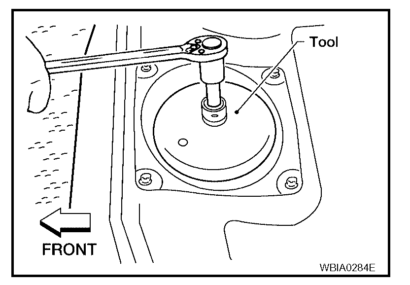
7. Remove the lock ring using Tool as shown.
Tool number : - (J-46214)
CAUTION:
- Discard the lock ring, do not reuse the lock ring.
- Discard the ring seal, do not reuse the ring seal.
8. Remove the fuel level sensor, fuel filter, and fuel pump assembly.
CAUTION:
- Do not bend the float arm during removal.
- Discard the ring seal, do not reuse the ring seal.
INSPECTION AFTER REMOVAL
Inspect the fuel level sensor, fuel filter, and fuel pump for any defects and foreign materials. Replace as necessary.
INSTALLATION
Installation is in the reverse order of removal.
- Install the fuel level sensor, fuel filter, and fuel pump assembly with the fuel feed hose facing the front of the vehicle as shown. Use a new ring seal.
- Connect the quick connector as follows:
- Check the connection for damage or any foreign materials.
- Align the connector with the tube, then insert the connector straight into the tube until a click is heard.
- After the tube is connected, make sure the connection is secure by performing the following checks:
- Pull the tube and the connector to make sure they are securely connected.
- Visually confirm that the two retainer tabs are connected to the quick connector.
INSPECTION AFTER INSTALLATION
Use the following procedure to check for fuel leaks.
1. Turn the ignition switch to ON (without starting the engine) to apply fuel pressure to the fuel system, then check the connections for fuel leaks.
2. Start the engine and let it idle and check for fuel leaks at the fuel system connections.
__________________________________________
Let me know if this helps or if you have other questions.
Take care,
Joe
Images (Click to make bigger)
Tuesday, May 25th, 2021 AT 1:29 PM