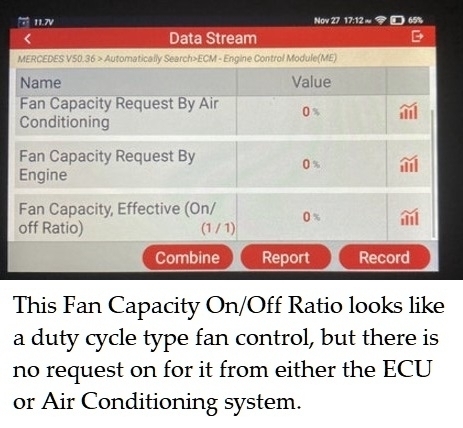
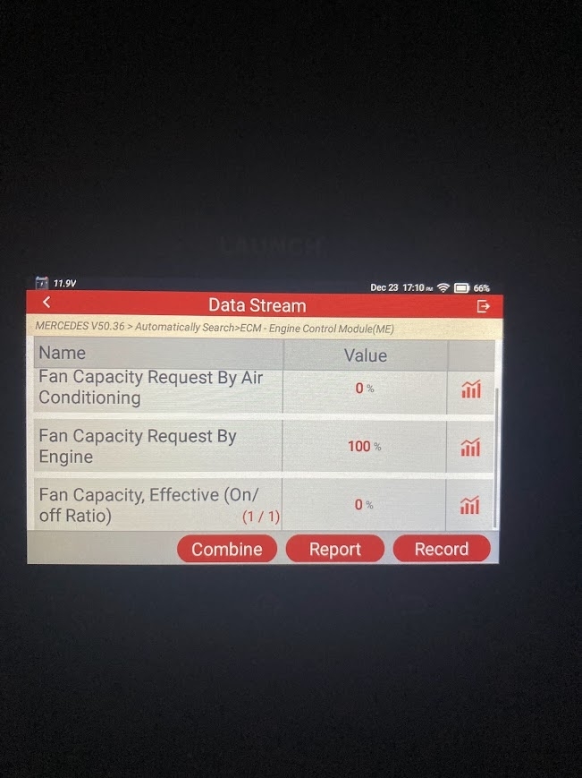
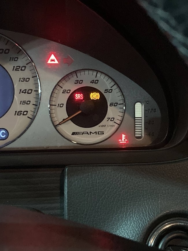
You should be able to see on your scan data the engine temperature sensor change to an open circuit number, usually a temp sensor defaults to -40f degrees when unplugged, and you could back probe the ECM connector to see what the Bus looks like there.
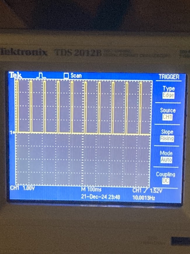
Pin 1 green/white wire (CAN-C High) and pin 11 green wire (CAN-C Low) (twisted pair), if you have only a 2 channel scope you can go across those 2 pins and should see a bias voltage of 2.5volts, which is what the Can signal rides on. Can High should go from 2.5v to 3.5v and Can Low should be 2.5v down to 1.5v. Really youre looking for any weird sloping lines in the network signals, I like to take a first capture of a longer time base, that way I can see the very slight differences in each message packet, which is something you will notice. Each packet wont be exactly 3.5v up for example, but the slight differences are different modules communicating on the network. Its not easy by any means, I understand fully of not being 100% sure of what you might be looking at, I cant tell, just by a weird waveform, what the fault is, but when a square wave just doesnt look right you'll notice it, especially since youre a scope user which is really great. Not enough techs use them, I try to use for anything possible. If you have a good running vehicle around, take a look at its can bus so you can see what a good signal looks like. You can do a lot with just a 2 channel scope.
I was wondering if that signal changes at all with the ECM plugged in, does the scope capture have any change at all.
Monday, December 16th, 2024 AT 8:40 AM