Did you find 12 volts on both motor wires when a switch was pressed? If so, next, unplug one of the wires from the motor, (both is okay too if they're in one connector). The idea is to separate them for testing so the bad circuit doesn't read "good" by reading through the motor to the other circuit.
If you want to use an ohm meter, measure from each motor wire to ground. The hardest part of this task is to find a good ground for the meter. I use a small clip lead, (jumper wire), connected to the door striker. Otherwise, everything is covered with paint and you almost have to run a wire all the way back to the battery's negative post. You might find something to connect to on the sheet metal behind the side kick panel. There's usually a bunch of other ground wires bolted there.
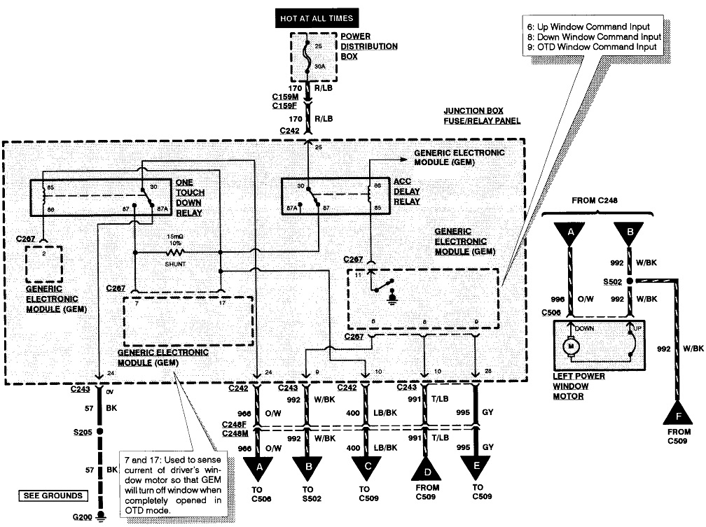
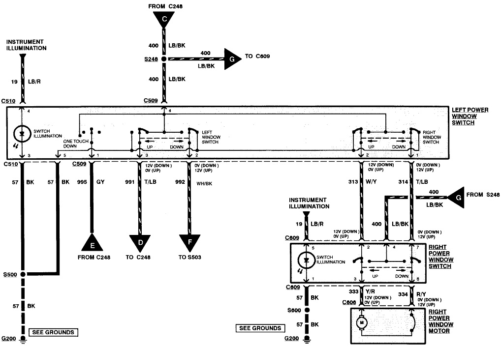
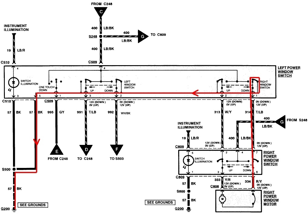
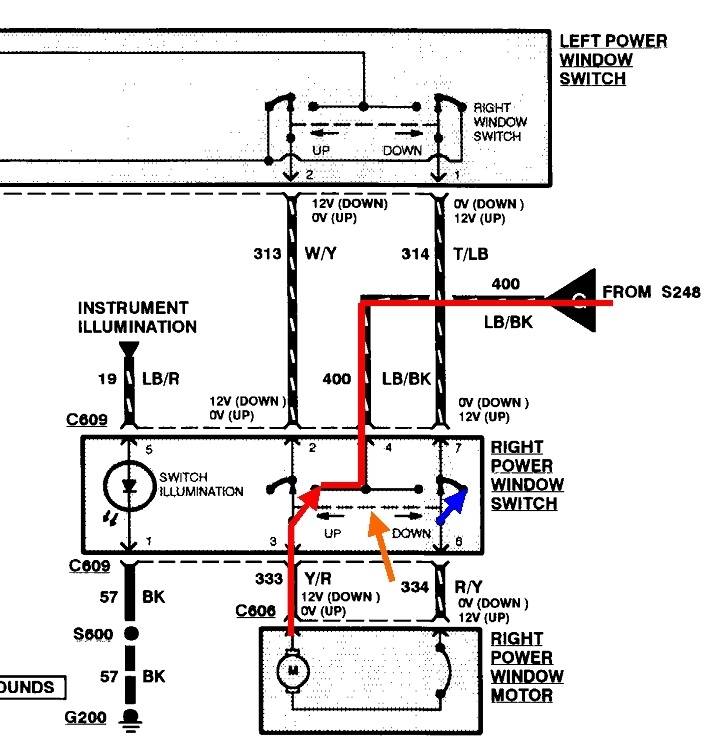
Following these circuits is a little tricky, but yours is no different than what everyone used for a long time. This first diagram is part 2 for reference before I muddy it all up with lines and stuff. The second one is the same diagram, but I highlighted the current path for one of the two circuits. All of the switches are released. Everything we need for the right window is on this one diagram. Starting at the motor, the red line goes up through one switch that is on, (released), then through both sets of front door hinges and over to the driver's switch. It continues up through that switch which is also released, coils around, then runs to the left, out through terminal # 5, black wire, through splice S500, then to ground, G200. The important point here is current runs through two sets of switch contacts, one set in each side, when they're not being pressed. Actually, I might be confusing that even more. There's really no current flow. There is CONTINUITY through each circuit.
That was for just one motor wire. The other wire runs through a similar path, through two other sets of released switch contacts. This might not make sense yet, but there's four switches involved so far. This shows why each wire must have continuity to ground. You're going to find one of yours doesn't.
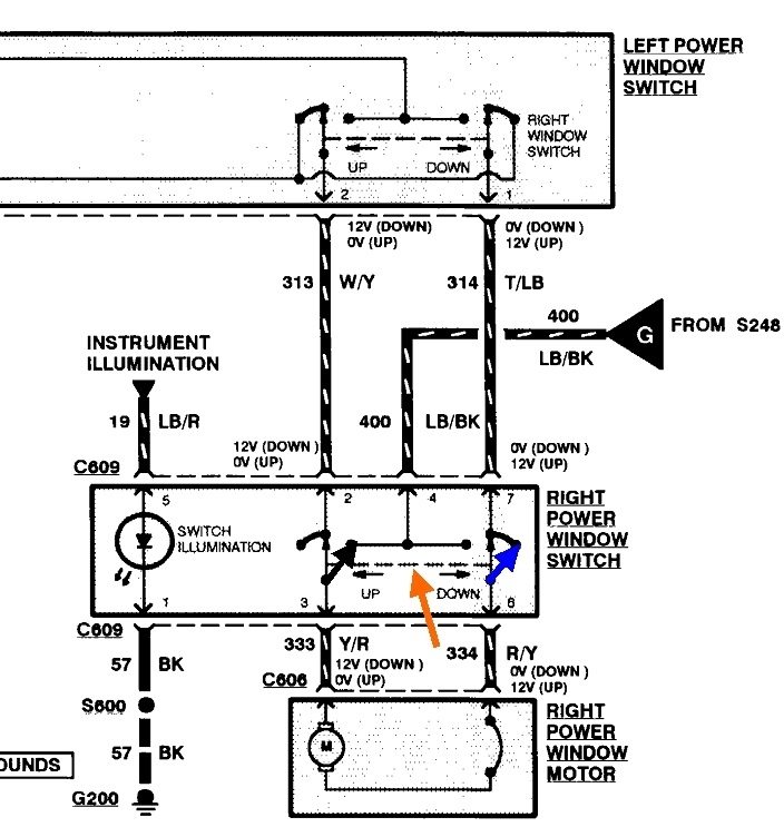
You may gloss over this paragraph unless you live to see how much confusion you can endure. In each window switch, there's two individual switches. Only one moves when you press "up", and only the other one moves when you press "down". Most of the time diagrams are drawn to show those as two separate switches, but here, to try to ease the explanation, they drew the switches a little differently. First, note the dashed line between the two switches, (orange arrow in the third diagram). That means they physically move together, at the same time. The results and circuit operation are the same, regardless which way you look at it.
Still in the third diagram, "down" has been pressed on the passenger's switch. The right switch, (blue arrow), moved to the right, but it's still making contact the same as when it was released. That circuit is still connected to ground. The excitement starts where the left switch has moved, (red arrow). When there's a master cutout switch on the driver's switch assembly, that is where the 12 volts comes from, so that's a third wire running through the door hinges that could be broken. The left switch, (red arrow), has moved away from ground, it's at-rest position, and is connected now to the 12-volt terminal inside the switch, so now you have 12 volts to one motor wire and the other wire is still connected to ground. The window runs down.
When "up" is pressed, the left switch stays put on ground, and the right one moves from the ground terminal to the 12-volt terminal, just like before. This puts the 12 volts on the motor's other wire, so it runs the other way. The same thing can be done at the driver's switch. To boil this down, when released, all four switches connect their circuits to ground. When any switch is pressed, it breaks the ground connection, then it puts 12 volts on that circuit.
Now, in case that didn't confuse you enough yet, I'm going to add one more tidbit. You can use an ohm meter to measure continuity, but that is the least accurate method. Voltage readings are much more accurate, but only if you use an inexpensive test light instead of a digital voltmeter. If a flexing wire between the door hinges is so badly frayed that not enough current can get through to run the motor, all it takes is one tiny strand still intact for the ohm meter to falsely "see" good continuity. A digital voltmeter only needs the tiniest tickle of current to see 12 volts when you press a switch. In cases like this, the cheap test light with an incandescent bulb can be much more accurate as it needs substantial current flow to light up. If only one strand of wire is still intact, you won't get enough current through it to run the motor or to run the test light. Bothe require plenty of current, and a good, wire for that to happen. This same thing happens with fuse link wires. When they burn open, they arc and leave a carbon track behind inside the wire's insulation. That carbon can conduct enough current for a digital voltmeter to falsely see 12 volts. The test light won't get enough current through that carbon to light up, so it gives the accurate result.
There's a lot to digest. See how far you get with that. The next step, if necessary, is I'll have you just measure at one or two points, tell me what you find, then I'll tell you where to measure next. That may run into many days, but we can find the cause of the problem that way without you needing to know how the circuit works.
Images (Click to make bigger)
Thursday, February 8th, 2024 AT 5:34 PM