Would suspect the switch and or wiring
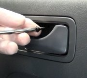
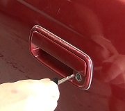
remove switch and inspect wiring in door jam
I will try and email u the pic
good luck
let me know
F150/F250 Light-Duty
Ensure ignition switch is off. Connect NGS tester to Data Link Connector (DLC). Using NGS tester, read IGN_GEM PID while rotating ignition switch through START, RUN, OFF and ACC positions. If PID values agree with ignition switch positions, go to next step. If PID values do not agree with ignition switch positions, repair suspect open circuit between ignition switch and instrument panel fuse block. Clear DTCs and retest system.
Following manufacturer's instructions, retrieve continuous DTCs from GEM. Using NGS tester, perform ON-DEMAND self-test. If no DTCs are present, go to next step. If DTCs B1405 (self-test) and B1408 (self-test) are present, go to step 4). If DTC B1410 (continuous and self-test) is present, go to step 10). If DTCs B1398 (continuous and self-test) and B1400 (continuous and self-test) are present, go to next step. If DTC B1342 is present, replace GEM. Clear DTCs and retest.
Turn ignition switch to RUN position. Using NGS tester, set active command DELAYED ACCESSORY ON. Read LFPWRLY PID. Toggle active command ONE TOUCH DOWN ON and OFF. If ACCDLY PID value agrees with command mode, go to step 9). If NGS tester indicates OFFO-G, go to next step. If NGS tester indicates ON-B-, go to step 7).
Turn ignition switch to OFF position. Check one-touch down relay . If one-touch down relay is okay, go to next step. If one-touch down relay does not test as specified, replace one-touch down relay. Clear DTCs and retest system.
Remove accessory delay relay from instrument panel fuse/relay block. Measure resistance between accessory delay relay socket terminal No. 87 and one-touch down relay socket terminal No. 85.

If resistance is less than 5 ohms, go to next step. If resistance is greater than 5 ohms, replace instrument panel fuse/relay block. Clear DTCs and retest system.
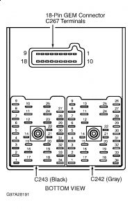
Disconnect 18-pin GEM connector from instrument panel fuse/relay block. Measure resistance between one-touch down relay terminal No. 86 and instrument panel fuse/relay block 18-pin GEM connector terminal No. 2.
Measure resistance between ground and one-touch down relay terminal No. 86. If resistance is less than 5 ohms between one-touch down relay and instrument panel fuse/relay block 18-pin connector, and greater than 10 k/ohms between one-touch down relay and ground, replace GEM. If resistance is not as specified, replace instrument panel fuse/relay block. Clear DTCs and retest system.
Turn ignition switch to OFF position. Check one-touch down relay
If one-touch down relay is okay, go to next step. If one-touch down relay does not test as specified, replace one-touch down relay. Clear DTCs and retest system.
Disconnect 18-pin GEM connector from instrument panel fuse/relay block. Turn ignition switch to RUN position. Measure voltage between ground and one-touch down relay socket terminal No. 86.
If voltage is present, replace instrument panel fuse/relay block. If voltage is not present, replace GEM. Clear DTCs and retest system.
Using NGS tester, read LFD_SW PID, LFU_SW PID, and OTD_SW PID while pressing master window switch in UP, DOWN, and AUTO positions. If PID values do not agree with values specified in master switch input table, go to next step.
If PID values agree with values specified in master switch input table, go to step 16).
Turn ignition switch to OFF position. Remove and disconnect master window switch 4-pin connector . Turn ignition switch to RUN position. Using NGS tester, enter active command mode DELAYED ACCESSORY. Set active command mode to ON. Measure voltage between ground and master window switch connector Light Blue/Black wire. If voltage is greater than 10 volts, go to next step. If voltage is less than 10 volts, repair Light Blue/Black wire. Clear DTCs and retest system.
Using NGS tester, read LFD_SW PID, LFU_SW PID, and OTD_SW PID. Connect a jumper wire between master switch 4-pin connector Light Blue/Black wire and Gray wire terminals while reading NGS tester. Disconnect jumper wire and reconnect jumper wire between master switch 4-pin connector White/Black wire and Tan/Light Blue wire terminals. If PIDs LFD_SW and OTD_SW indicate DOWN, and PID LFU_SW indicates UP with jumpers connected, replace master switch. Clear DTCs and retest system. If PIDs do not indicate DOWN or UP as specified, go to next step.
Turn ignition switch to OFF position. Disconnect instrument panel fuse/relay block Black connector C243. Measure resistance in Tan/Light Blue wire between master switch 4-pin connector and instrument panel fuse/relay block Black connector C243 terminal No. 10. Measure resistance between ground and Tan/Light Blue wire at master switch 4-pin connector. If resistance is less than 5 ohms between master switch and fuse/relay block Black connector C243, and greater than 10 k/ohms between ground and master switch 4-pin connector, go to next step. If resistances are not as specified, repair Tan/Light Blue wire. Clear DTCs and retest system.
Measure resistance in White/Black wire between master switch 4-pin connector and instrument panel fuse/relay block Black connector C243 terminal No. 9. . Measure resistance between ground and White/Black wire at master switch 4-pin connector. If resistance is less than 5 ohms between master switch and fuse/relay block Black connector C243, and greater than 10 k/ohms between ground and master switch 4-pin connector, go to next step. If resistances are not as specified, repair White/Black wire. Clear DTCs and retest system.
Measure resistance in Gray wire between master switch 4-pin connector and instrument panel fuse/relay block Black connector C243 terminal No. 28. Measure resistance between ground and Gray wire at master switch 4-pin connector. If resistances are less than 5 ohms between master switch and fuse/relay block Black connector C243, and greater than 10 k/ohms between ground and master switch 4-pin connector, go to next step. If resistance is greater than 5 ohms, repair open in Gray wire. Clear DTCs and retest system.
Turn ignition switch to OFF position. Disconnect 18-pin GEM connector from instrument panel fuse/relay block. Measure resistance between instrument panel fuse/relay block 18-pin GEM connector terminal No. 8 and instrument panel fuse/relay block Black connector C243 terminal No. 10. Measure resistance between instrument panel fuse/relay block 18-pin GEM connector terminal No. 6 and instrument panel fuse/relay block Black connector C243 terminal No. 9. Measure resistance between instrument panel fuse/relay block 18-pin GEM connector terminal No. 9 and instrument panel fuse/relay block Black connector C243 terminal No. 28. If resistances are less than 5 ohms, replace GEM. If resistances are greater than 5 ohms, replace instrument panel fuse/relay block. Clear DTCs and retest system.
Turn ignition switch to OFF position. Disconnect left front window motor connector. Turn ignition switch to RUN position. Using NGS tester, set active command ONE TOUCH DOWN ON. Measure voltage between ground and left front window motor connector Orange/White wire. If voltage is less than 10 volts, exit active command mode and go to next step. If voltage is present, go to step 20).
Turn ignition switch to OFF position. Disconnect one-touch down relay from instrument panel fuse/relay block. Measure resistance between one-touch down relay socket terminal No. 30 and left front window motor connector Orange/White wire. If resistance is greater than 5 ohms, go to next step. If resistance is less than 5 ohms, go to step 19.
Turn ignition switch to OFF position. Disconnect instrument panel fuse/relay block Gray connector C242. Measure resistance in Orange/White wire between instrument panel fuse/relay block Gray connector C242 terminal No. 24 and left front window motor connector. If resistance is less than 5 ohms, replace instrument panel fuse/relay block. If resistance is greater than 5 ohms, repair open in Orange/White wire. Clear DTCs and retest system.
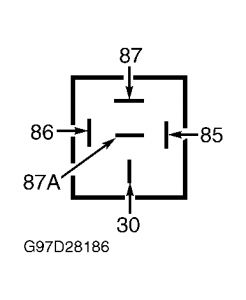
Disconnect accessory delay relay from instrument panel fuse/relay block. Measure resistance between one-touch down relay socket terminal No. 87 and accessory delay relay socket terminal No. 87. See Fig. 3 . If resistance is less than 5 ohms, replace one-touch down relay. If resistance is greater than 5 ohms, replace instrument panel fuse/relay block. Clear DTCs and retest system.
Using NGS tester, set active command ONE TOUCH DOWN OFF. Turn ignition switch to OFF position. Measure resistance between ground and left front window motor connector Orange/White wire. If resistance is greater than 5 ohms, go to next step. If resistance is less than 5 ohms, go to step 23).
Disconnect one-touch down relay from instrument panel fuse/relay block. Measure resistance between ground and one-touch down relay socket terminal No. 87A. If resistance is greater than 5 ohms, go to next step. If resistance is less than 5 ohms, replace one-touch down relay. Clear DTCs and retest system.
Disconnect instrument panel fuse/relay block Black connector C243. Measure resistance between ground and instrument panel fuse/relay block Black connector C243 terminal No. 24 (Black wire). If resistance is less than 5 ohms, replace instrument panel fuse/relay block. If resistance is greater than 5 ohms, repair open in Black wire. Clear DTCs and retest system.
Turn ignition switch to RUN position. Measure voltage between ground and left front window motor connector White/Black wire while pressing left front window switch in UP position. If voltage is greater than 10 volts, replace left front window motor. If voltage is less than 10 volts, repair open in White/Black wire. Clear DTCs and retest system.
Wednesday, June 3rd, 2009 AT 6:06 AM