Welcome to 2CarPros.
Most likely you have a blown head gasket. I would start by checking for evidence of a head gasket leak. Here is a link to help:
https://www.2carpros.com/articles/head-gasket-blown-test
If you determine the gasket is bad, here are directions for replacing it. You indicated a 1.5L That wasn't an option. Either a 1.6L or a 1.8L were available. So, I will provide directions for both. First will be the 1.6L. The attached pictures correlate with the directions. Also, there are a lot of directions. However, you will only need the one related to your engine's size.
_________________________
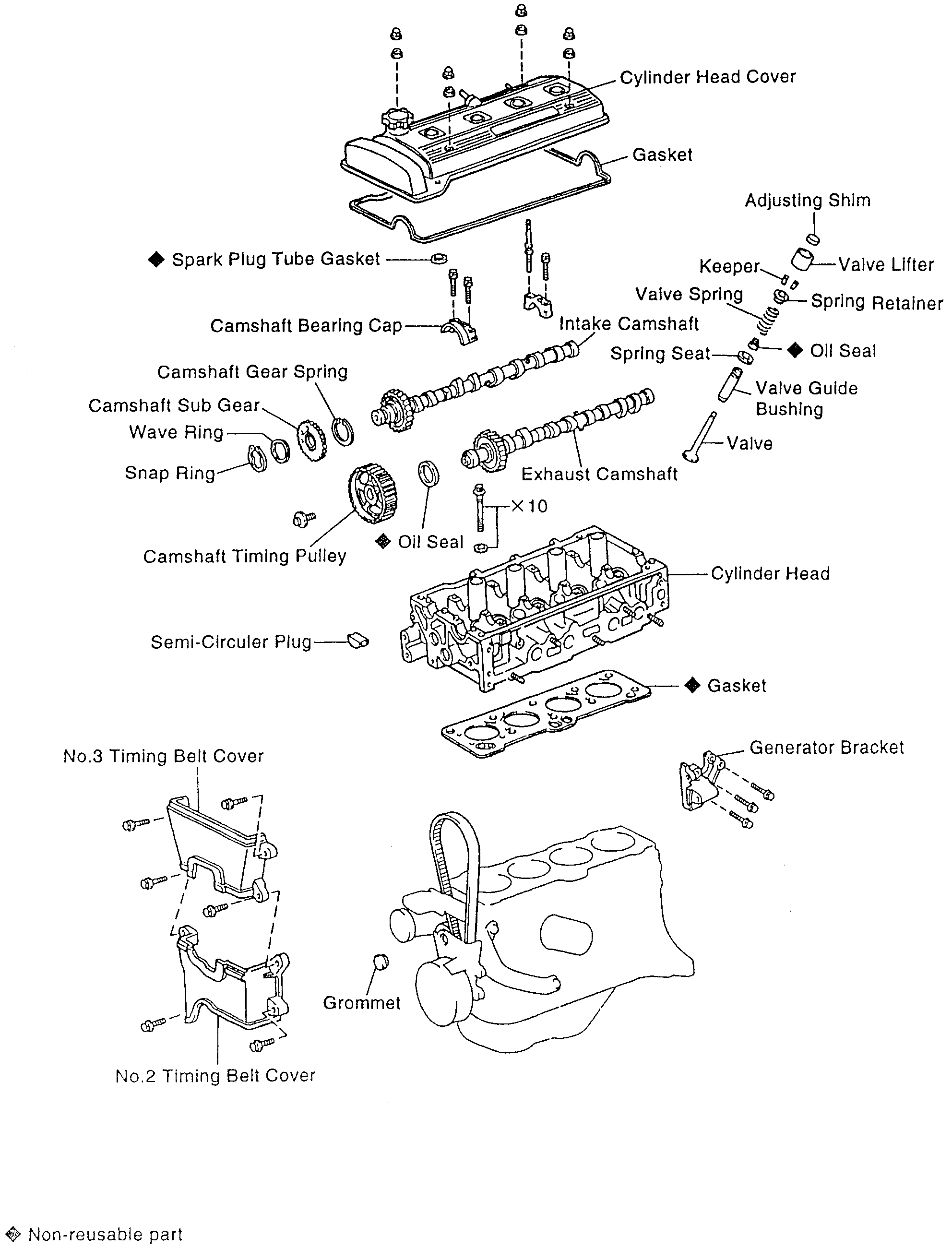
CYLINDER HEAD REMOVAL
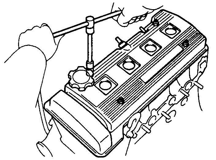
pic 1
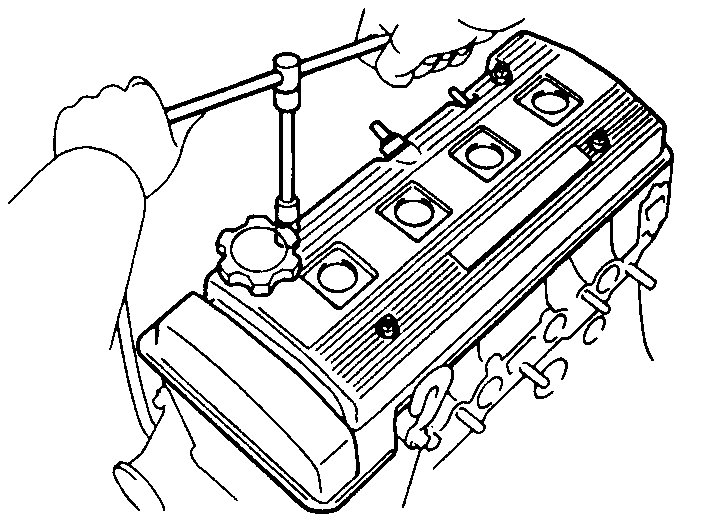
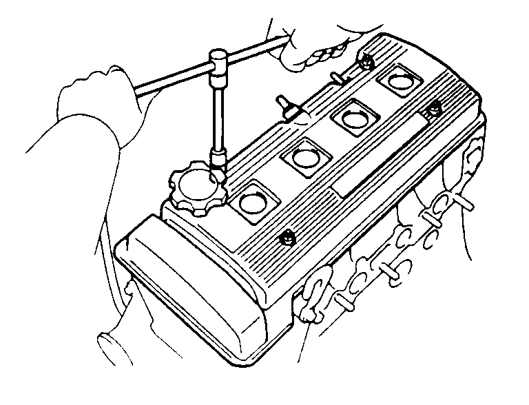
1. Remove the 4 cap nuts, seal washers, valve cover, gasket, and spark plugs.
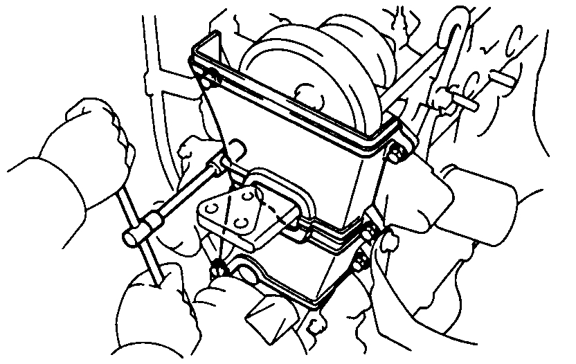
pic 2
2. Remove the 6 bolts, and the No.3 and No.2 timing belt covers.
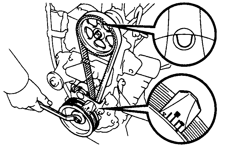
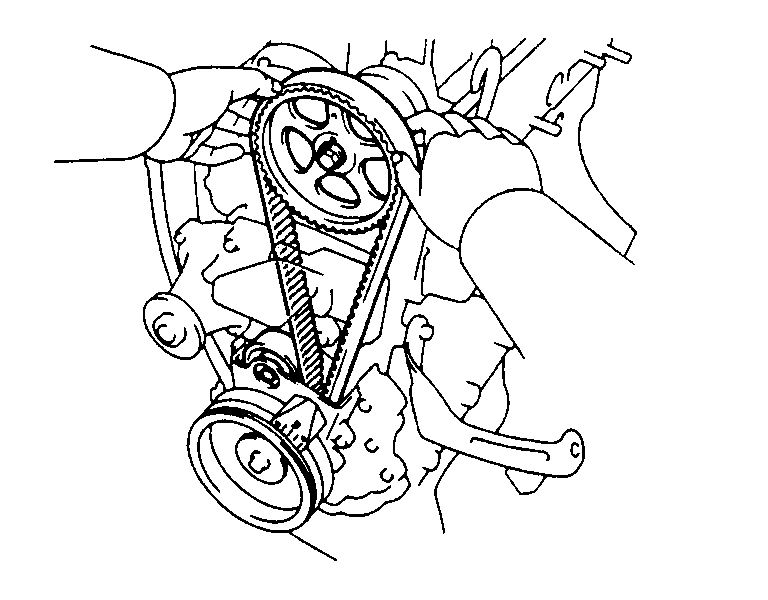
pic 3
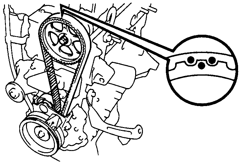
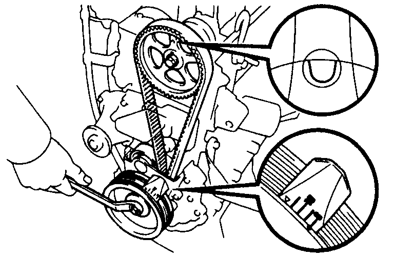
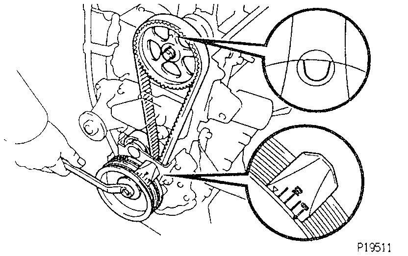
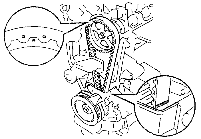
3. Turn the crankshaft pulley and align it's groove with the timing mark "0" of the No.1 timing belt cover.
4. Make sure that the hole of the cam timing pulley is aligned with the timing mark of the bearing cap. If not, turn the crank 1 complete revolution.
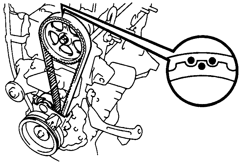
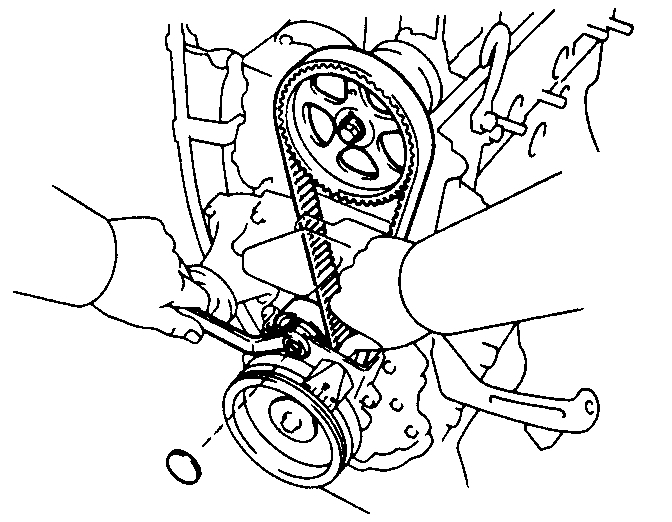
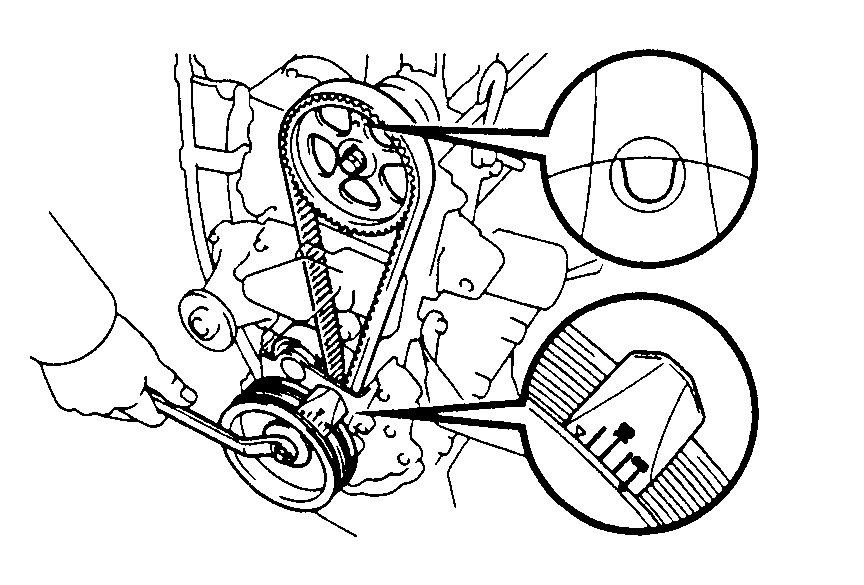
pic 4
5. Remove the timing belt from the cam pulley. If re-using the belt, mark it at this time as shown.
pic 5
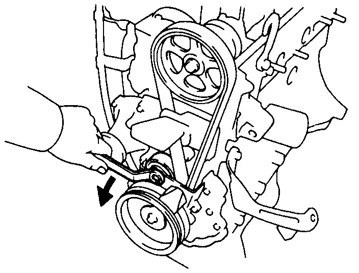
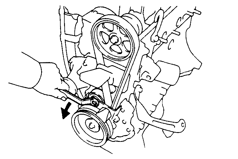
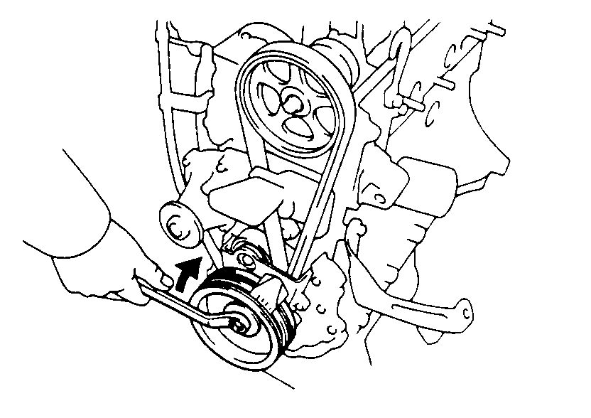
6. Remove the plug from the No.1 timing belt cover.
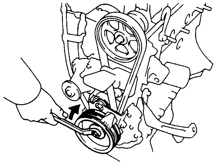
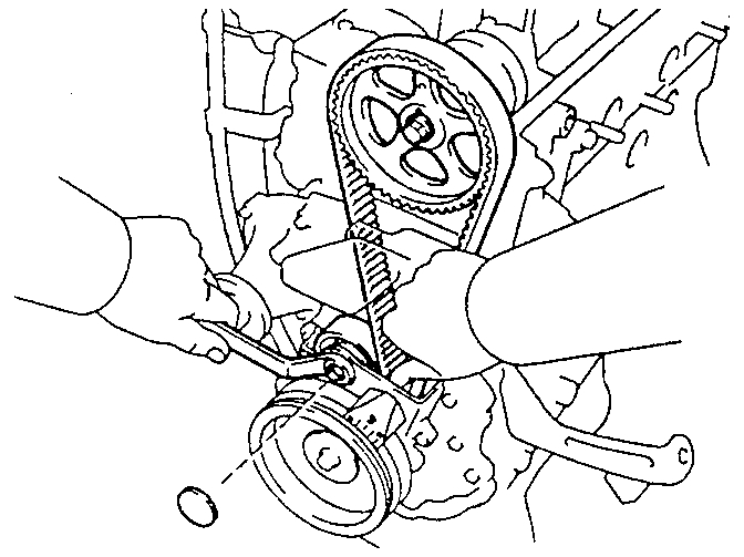
7. Loosen the idler pulley mounting bolt and push the idler pulley towards the left as far as it will go, temporarily tighten it.
NOTE:Keep belt area clean from foreign objects, water, oil or other substances. Support the belt so that the meshing of the crank timing pulley and timing belt do not shift.
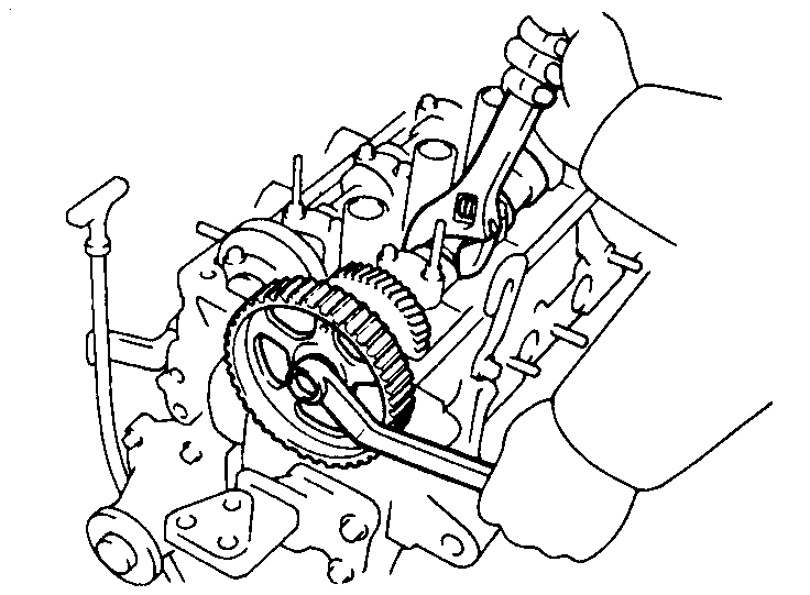
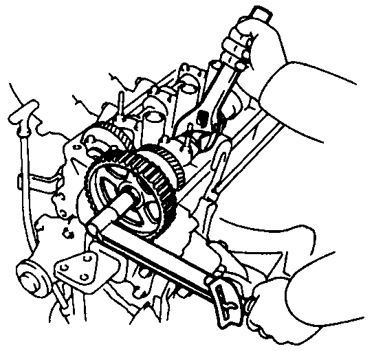
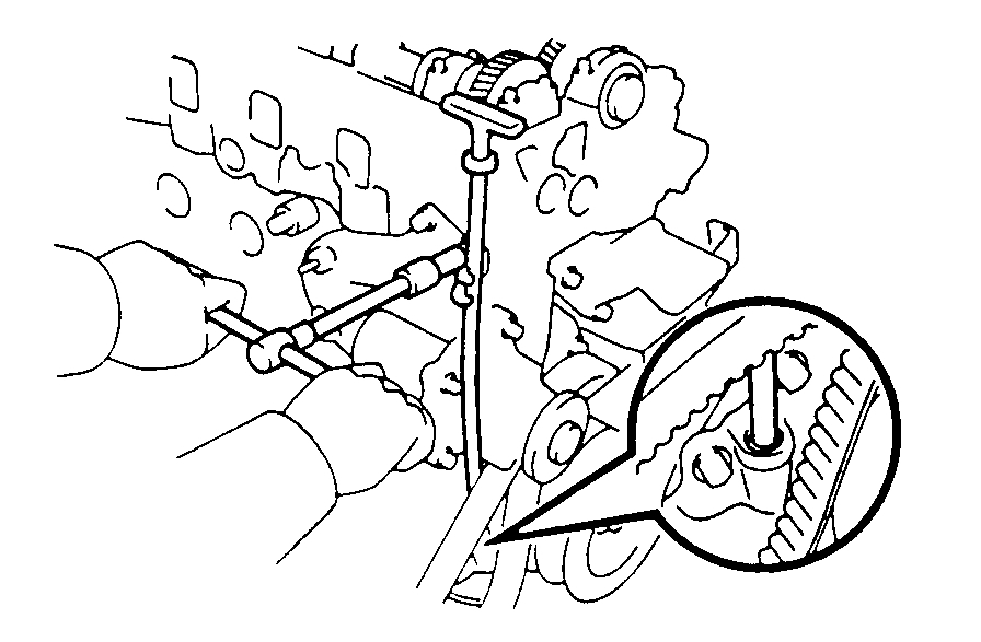
pic 6
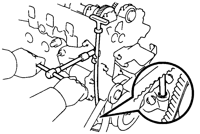
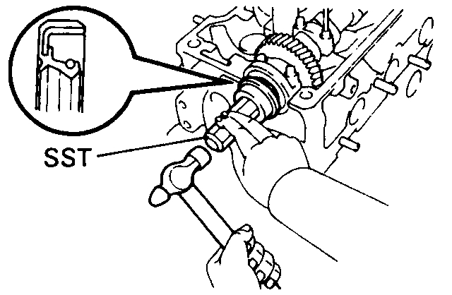
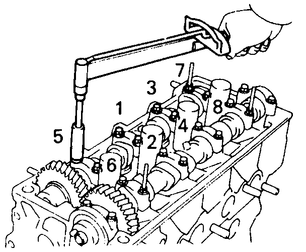
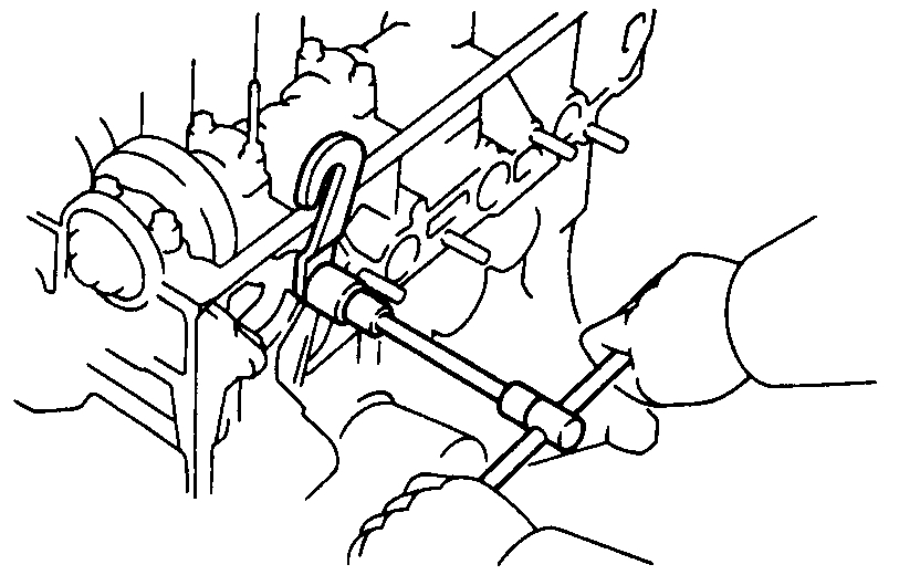
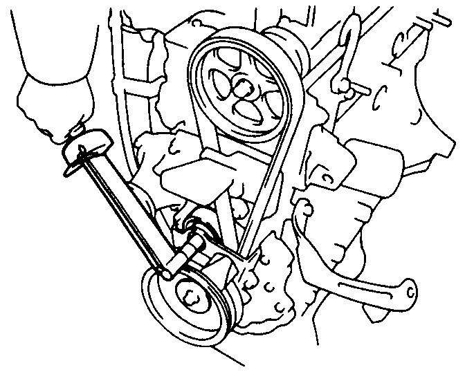
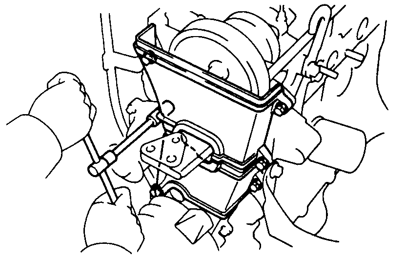
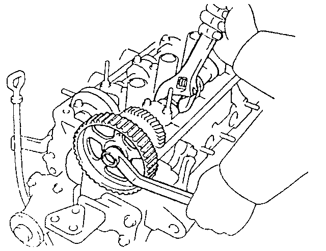
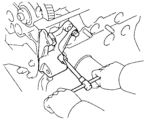
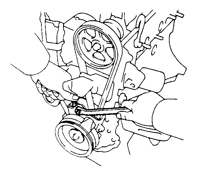
8. Hold the hexagonal head wrench portion of the cam with a wrench and remove the bolt and pulley.
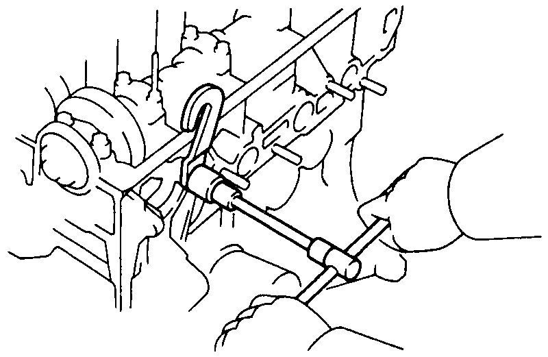
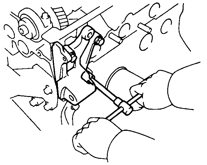
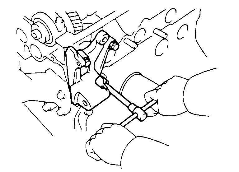
pics 7 and 8
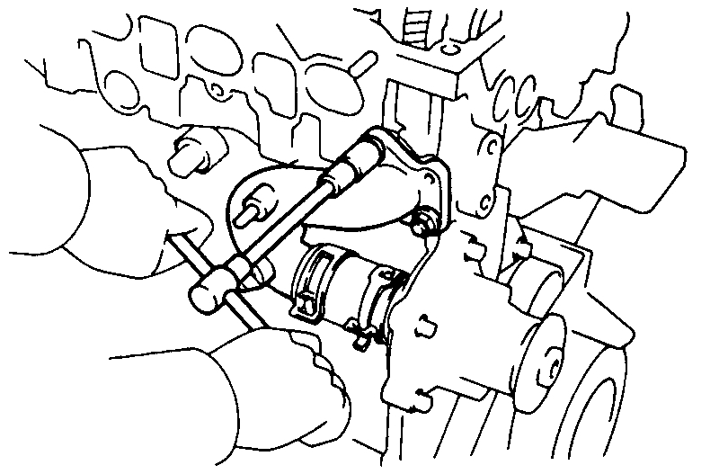
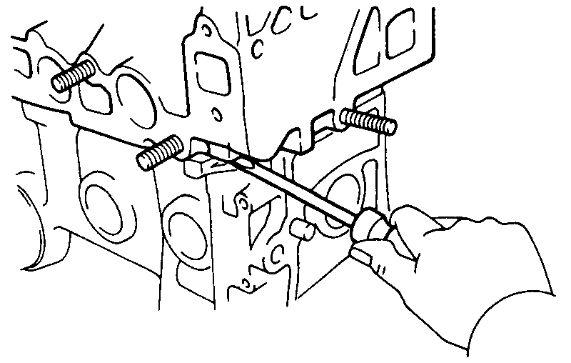
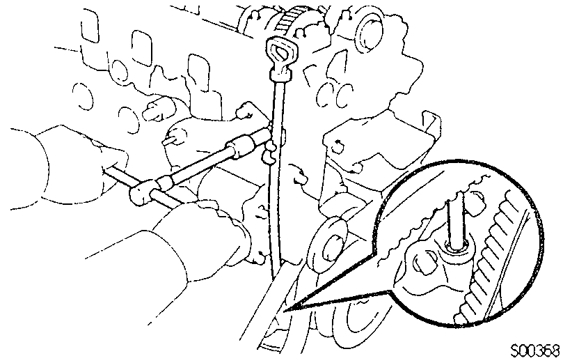
9. Remove the engine hanger and generator bracket.
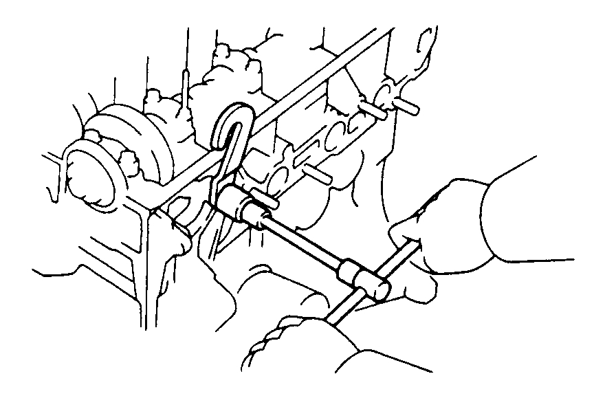
pic 9
10. Remove the dipstick, remove the mount bolt and pull out the dipstick guide. Remove the O-ring from the dipstick guide.
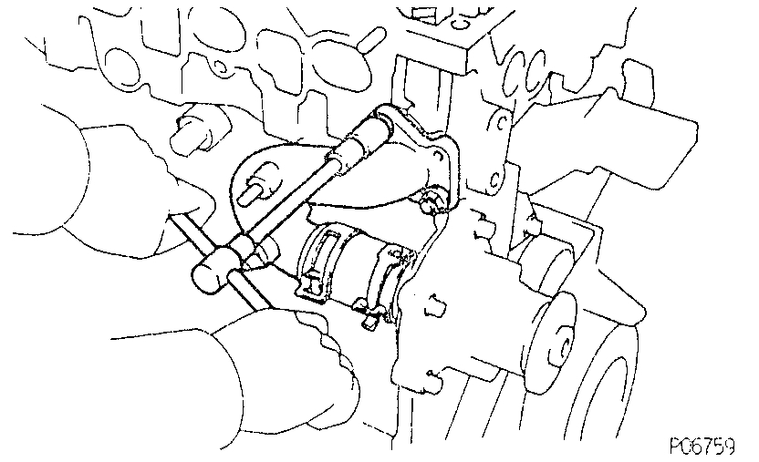
pic 10
11. Remove the 2 nuts and water inlet from the water inlet hose.
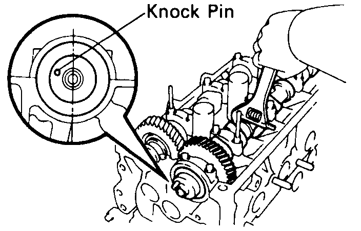
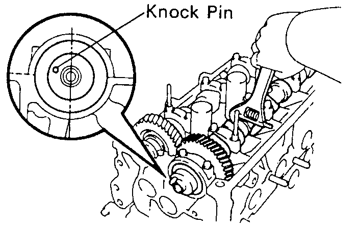
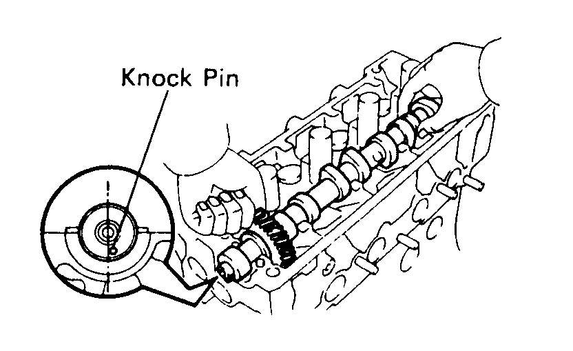
pic 11
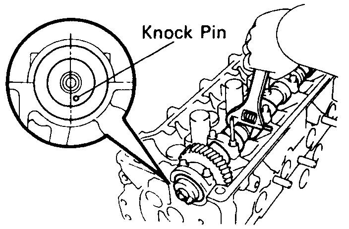
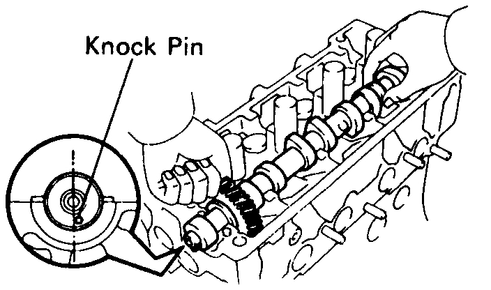
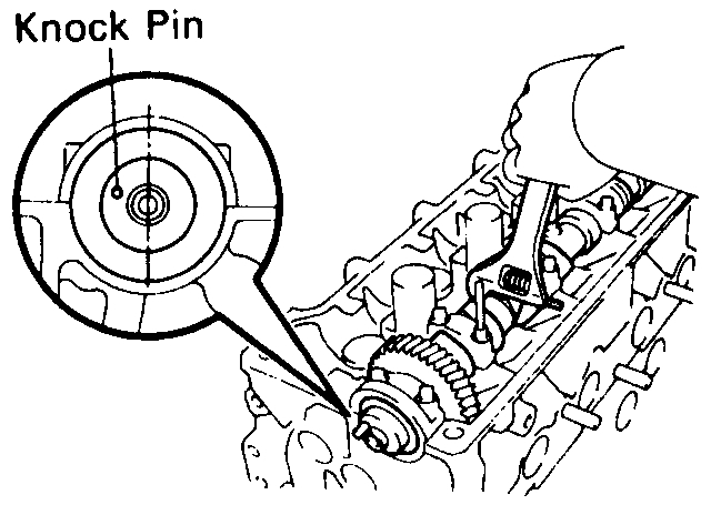
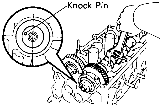
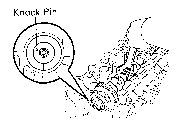
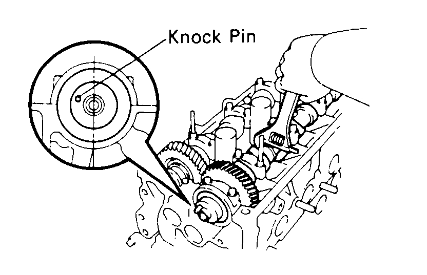
12. Set exhaust cam so the knock pin is slightly above the top of the cylinder head.
Caution: Keep camshaft level while removing, otherwise it may crack the cylinder head.
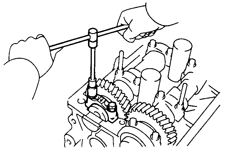
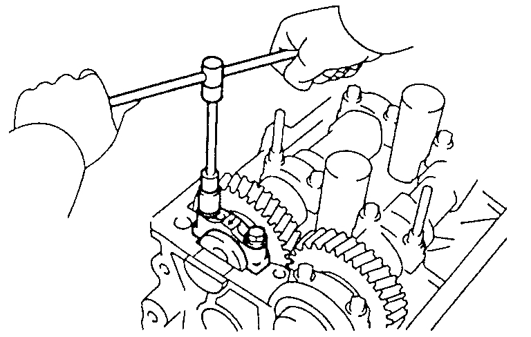
pic 12
13. Remove the 2 bolts and the front bearing cap.
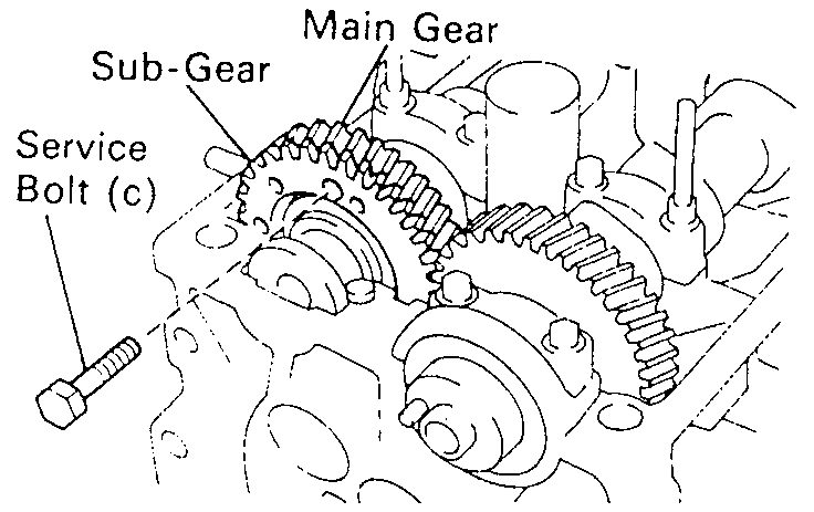
pic 13
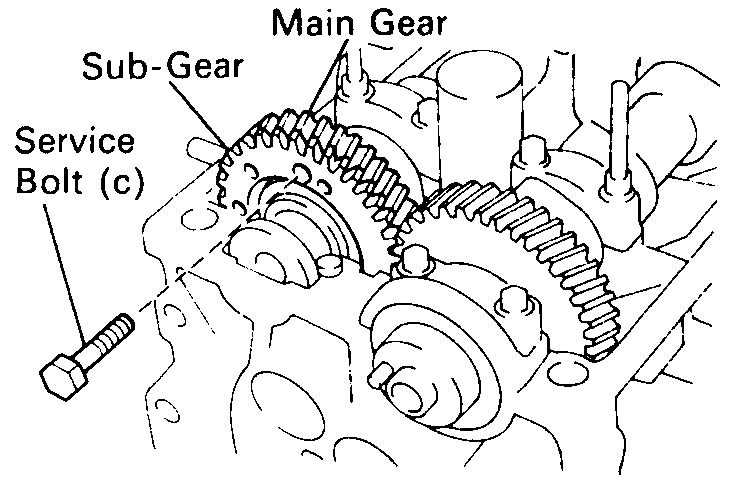
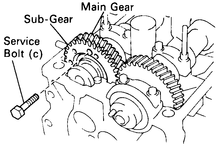
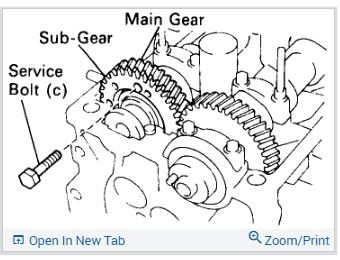
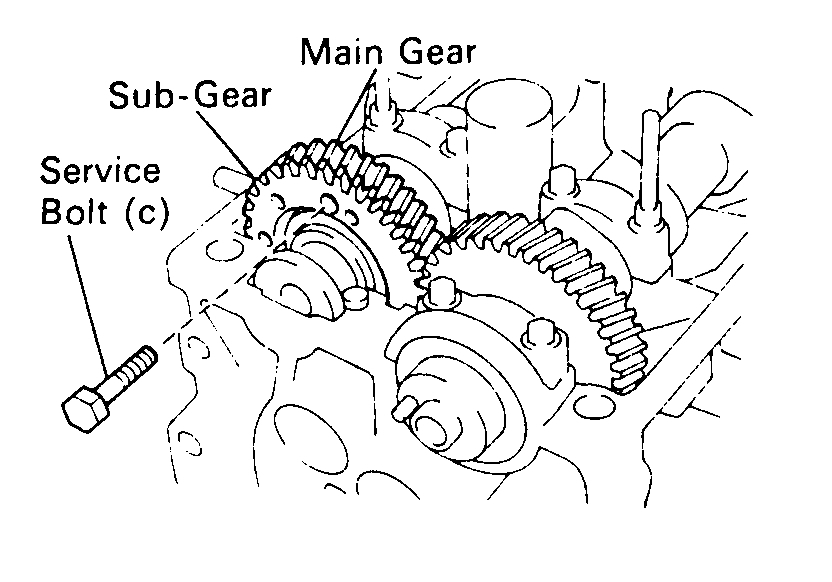
14. Secure the intake cam sub-gear to the main gear with a service bolt as shown. Recommended service bolt is 6mm thread diameter, 1.0mm thread pitch, and 16-20mm (0.63-0.79 in.) length.
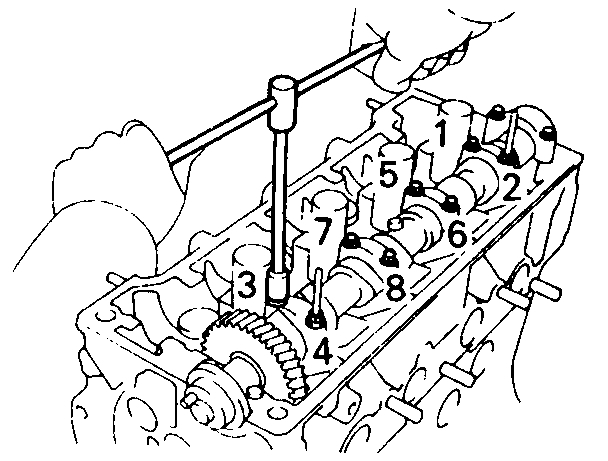
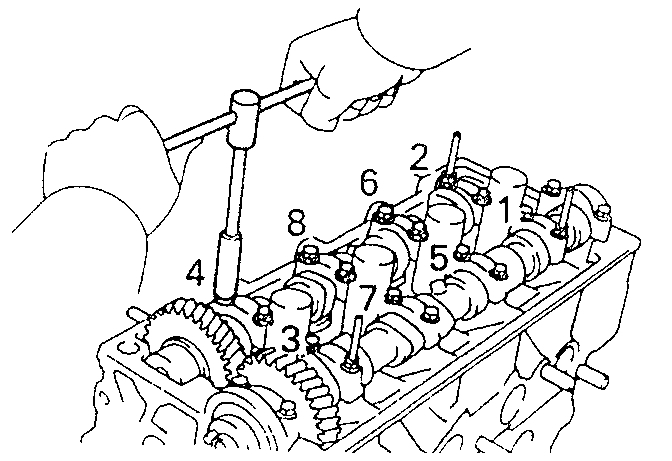
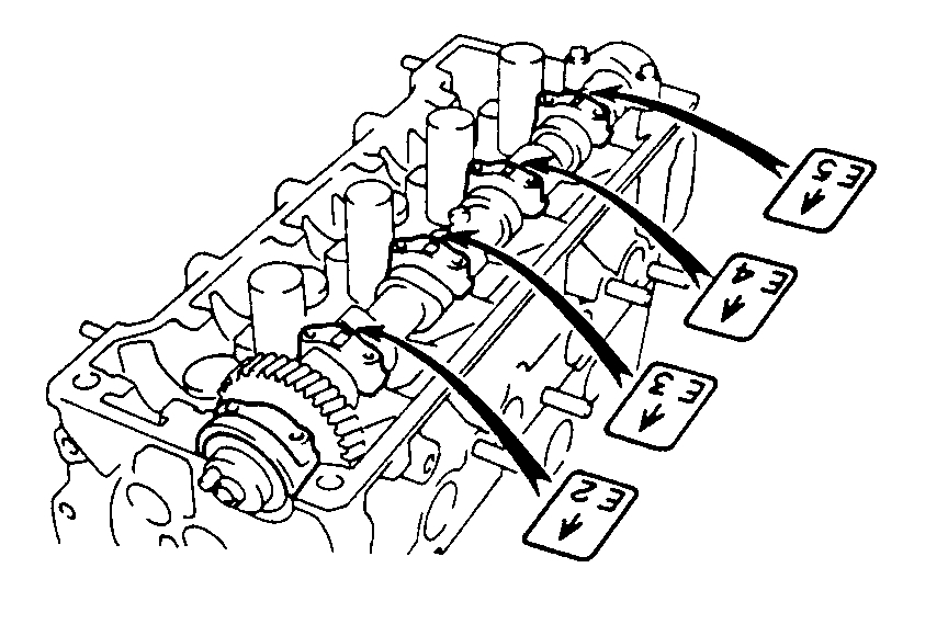
pic 15
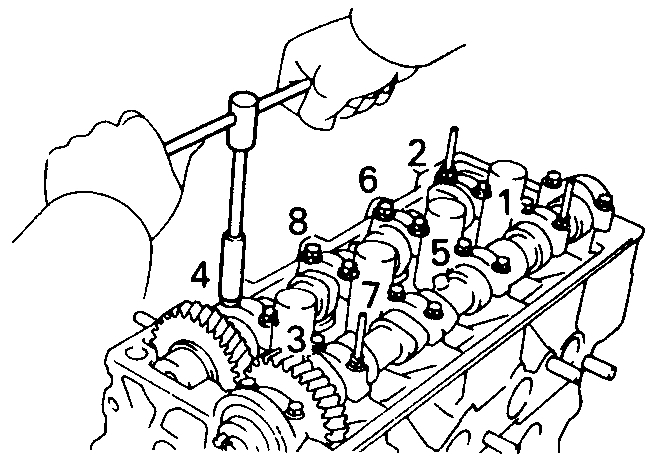
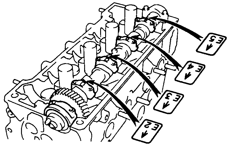
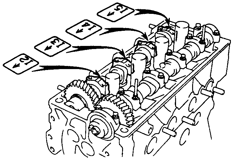
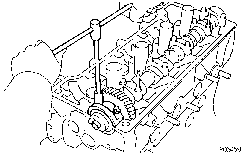
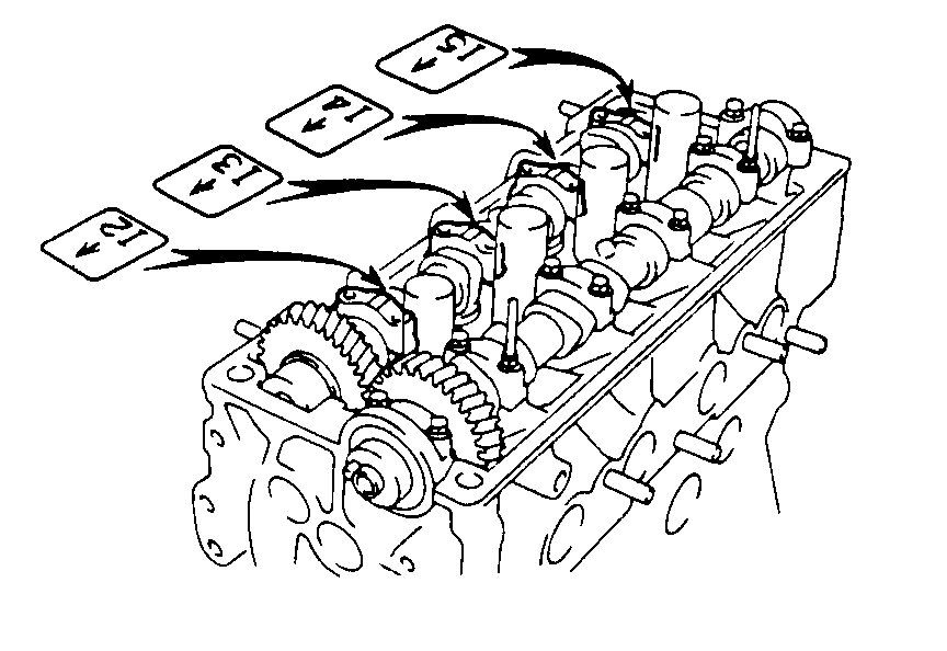
15. Remove the 8 bearing cap bolts in several passes in the sequence shown above, remove the 4 bearing caps and the camshafts.
Caution: Do not pry on or attempt to force the camshaft with a tool or other object.
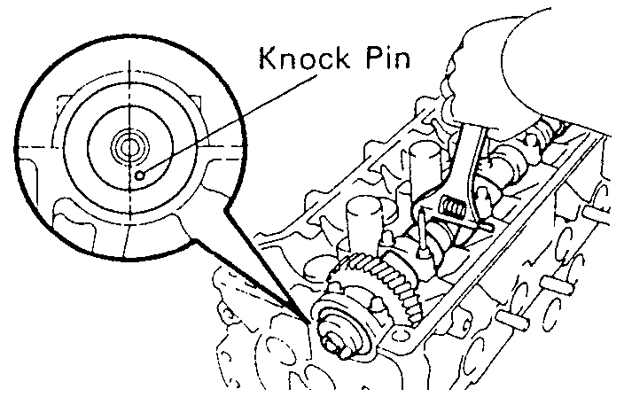
pic 16
16. Set the exhaust cam so the knock pin is located slightly counterclockwise from the vertical axis of the cam as shown.
pic 17
17. Remove the 2 bolts, front bearing cap and oil seal.
pic 18
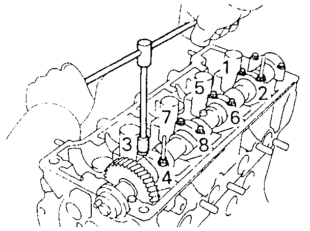
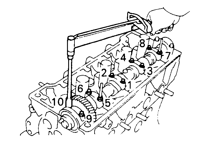
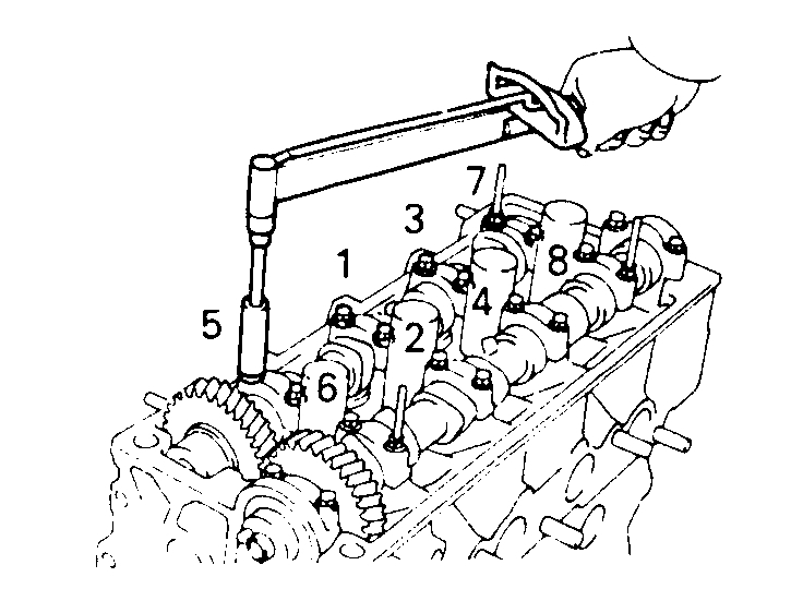
18. Remove the 8 bearing cap bolts in several passes in the sequence shown above, remove the 4 bearing cap bolts and camshaft.
pic 19
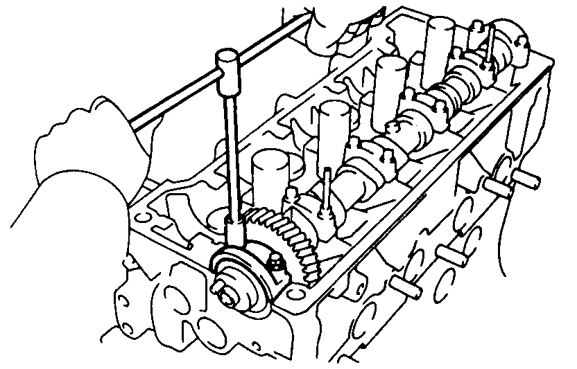
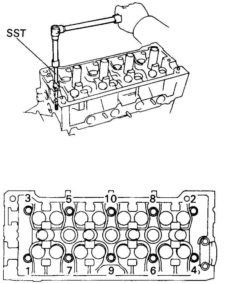
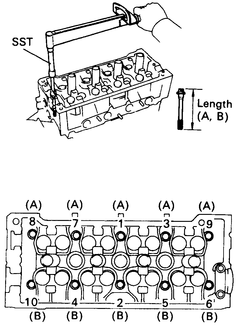
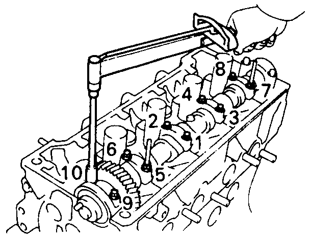
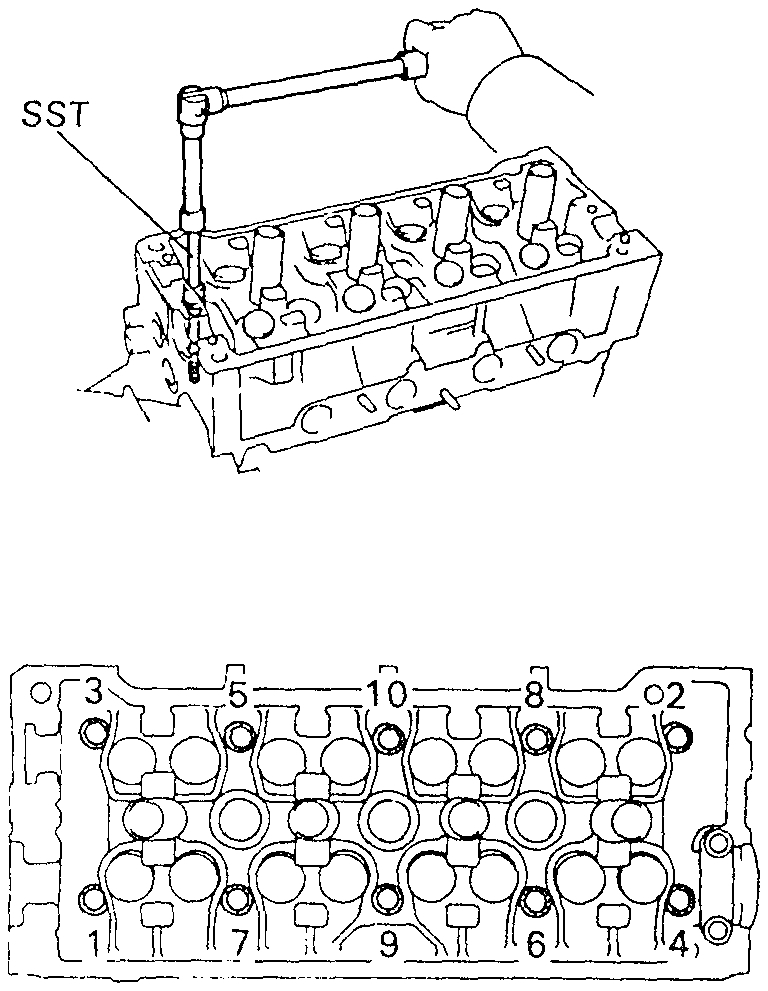
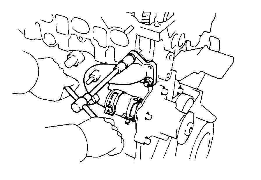
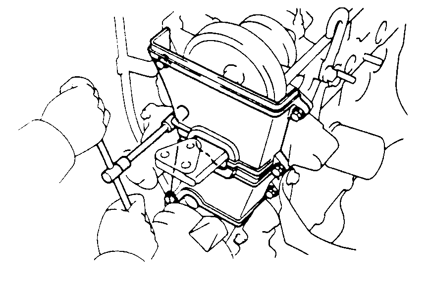
19. Using SST 09205-16010, loosen and remove the cylinder head bolts in several passes in the sequence as shown above.
Pic 20
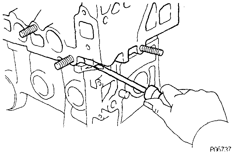
20. Lift the cylinder head from the dowels on the block and place the head on wooden blocks.
Note:If the cylinder head is difficult to lift off, pry with a screwdriver between the head and the block saliences. Do not damage the head or block mating surfaces when removing the head.
_______________________________
CYLINDER HEAD INSTALLATION / non California
pic 21
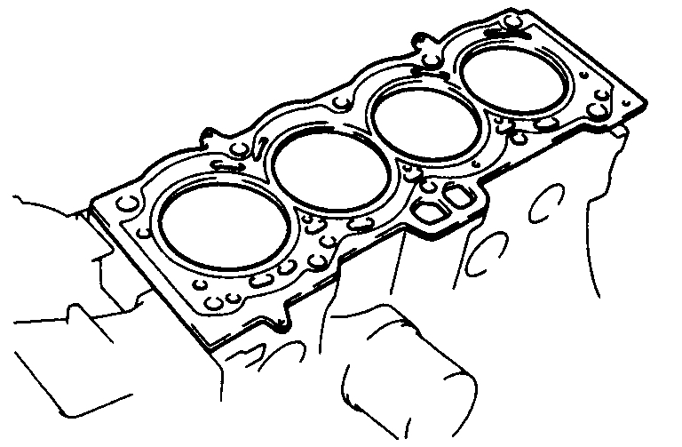
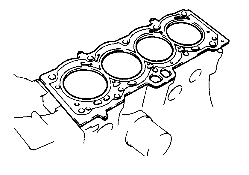
1. Place the new head gasket in position on the block as shown.
2. Carefully place the cylinder head in place on the gasket.
3. Apply a light coat of engine oil to the threads and underneath the heads of the head bolts at this time.
Caution: If any head bolt is broken or deformed in any way replace with a new one.
pic 22
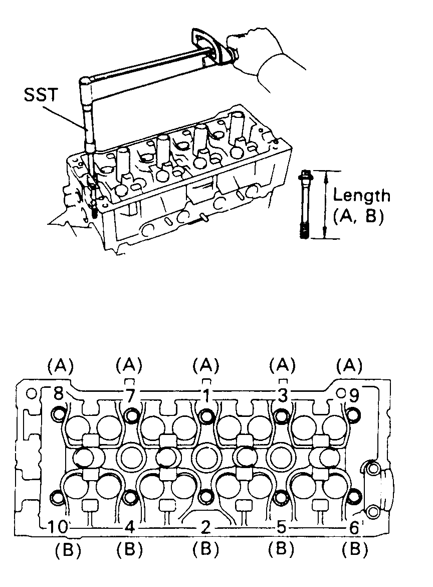
4. Using SST 09205-16010, install and tighten the 10 head bolts in several passes in the sequence shown above. Starting torque is 29 Nm (22 ft.lbs).
5. The bolts are of 2 different lengths. Length A is 90mm (3.54 in.) and goes to the intake manifold side. Length B is 108mm (4.25 in.) and goes to the exhaust manifold side.
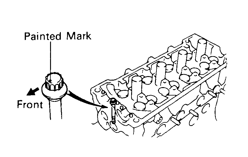
pic 23
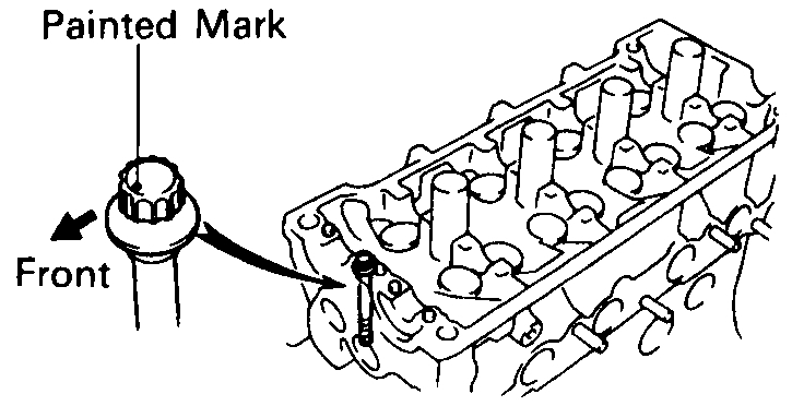
6. Mark the front of the head bolts with paint as shown.
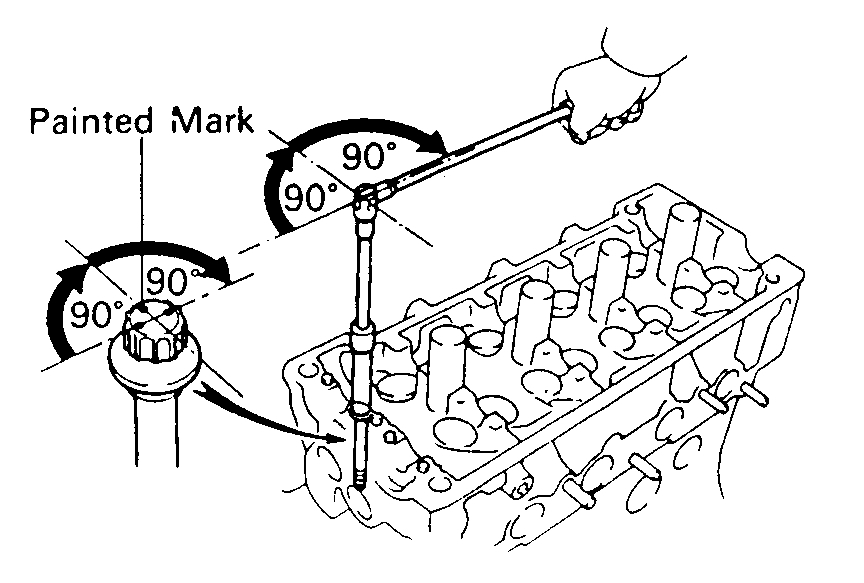
pic 24
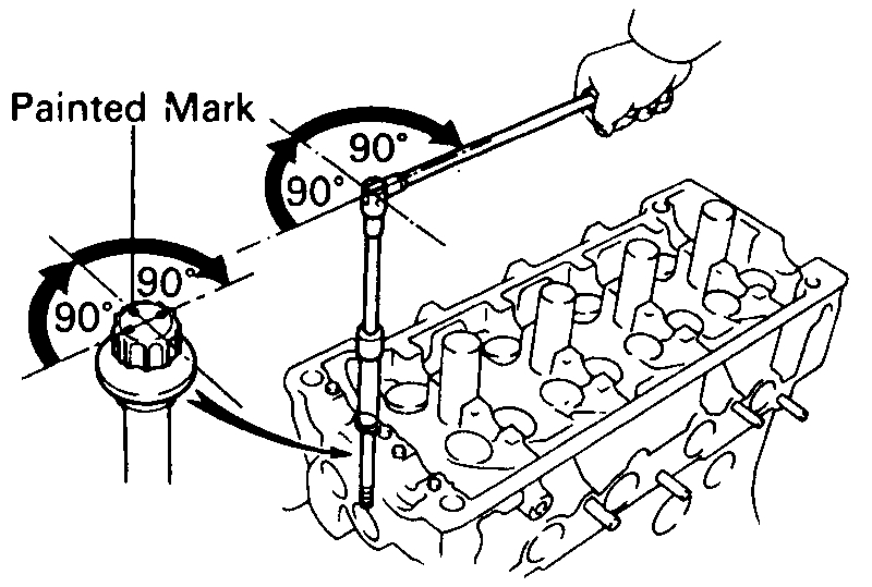
7. Torque the head bolts 90° in the same order as shown. Again torque the head bolts and additional 90° and make sure the paint marks now all point towards the rear of the engine.
Caution: Be careful to keep camshafts level while installing so as not to crack the cylinder head and/or seize the camshaft.
8. Apply MP grease to the thrust portion of the camshaft.
pic 25
9. Place the exhaust cam so the knock pin is located slightly counterclockwise from the vertical axis as shown.
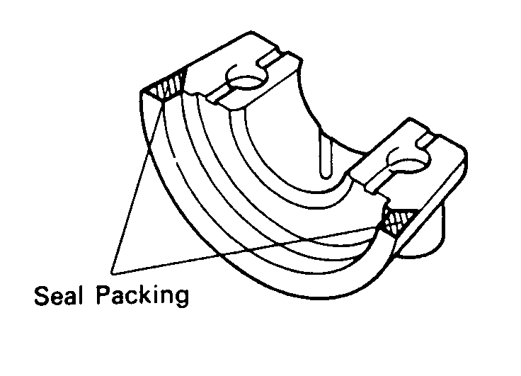
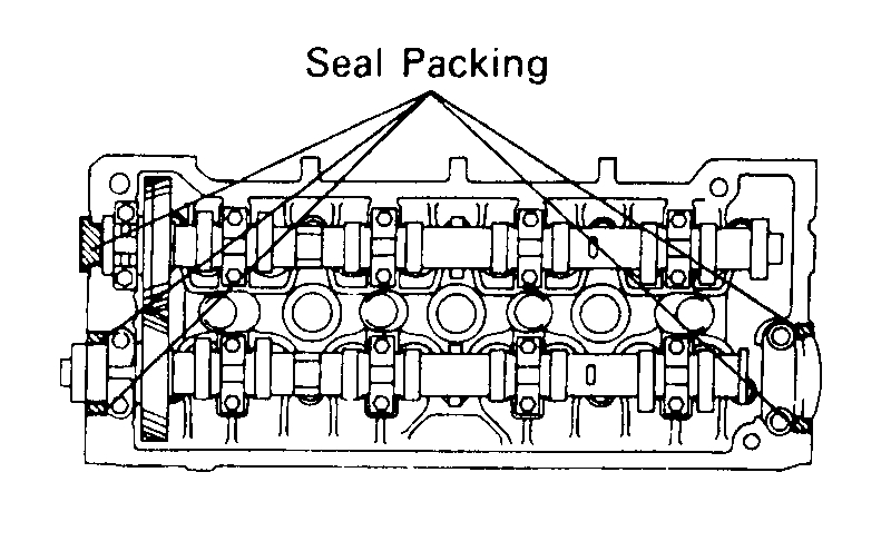
pic 26
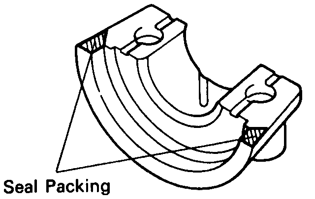
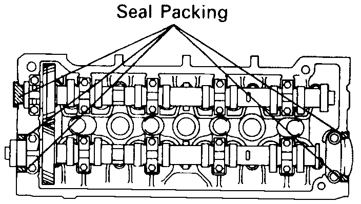
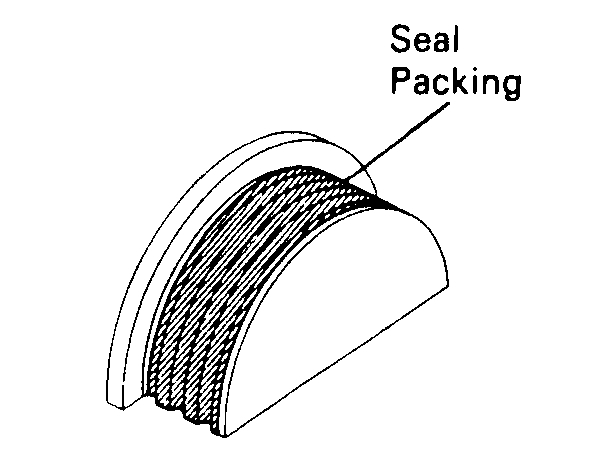
10. Remove any old packing material and apply new seal packing, part no. 08826-00080, to the cylinder head as shown.
pic 27
11. Install the bearing caps in their proper locations as shown above.
pic 28
12. Apply a light coat of engine oil to the threads and under the heads of the bearing cap bolts. Install and tighten the 10 cap bolts in the order shown, in several passes. Final torque is 13 Nm (9 ft.lbs).
pic 29
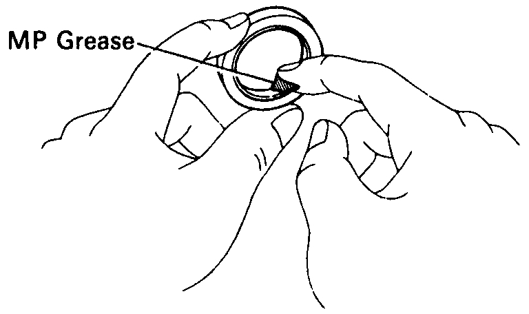
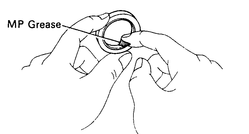
13. Apply MP grease to the new oil seal lip.
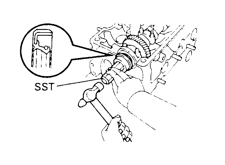
pic 30
14. Using SST 09223-46011, tap the oil seal in with the lip facing as shown above.
pic 31
15. set the exhaust cam so that the knock pin is slightly above the top of the cylinder head as shown above.
16. Apply MP grease to the thrust portion of the intake camshaft.
pic 32
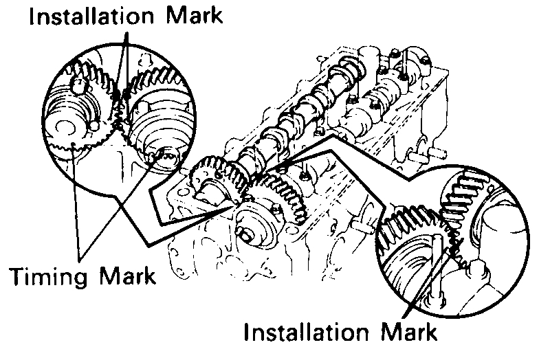
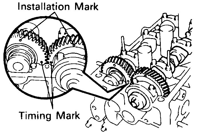
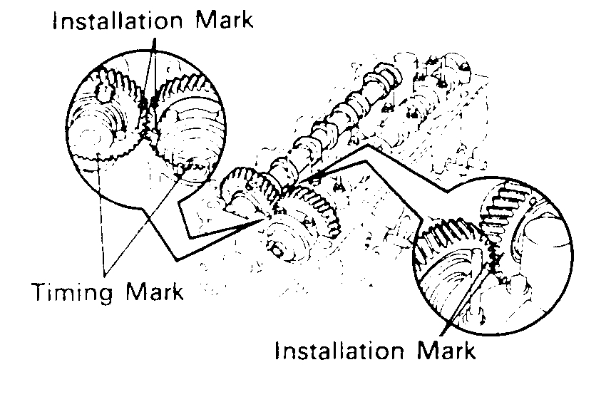
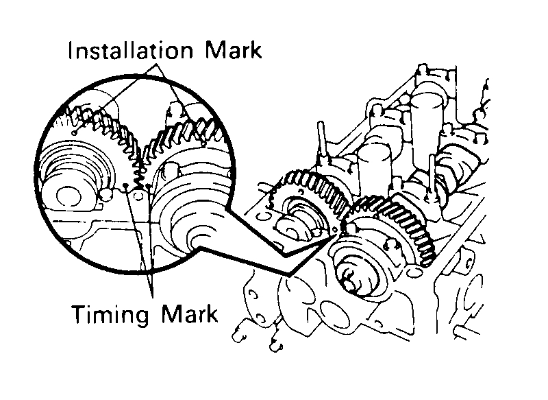
17. Engage the intake cam gear to the exhaust cam gear by matching the assembly installation mark on each gear as shown.
Caution: As shown, there are also timing (TDC) marks on the cam gears, do NOT use these marks to line the cam up with.
18. Roll down the intake cam onto the bearing journals while engaging the gears with each other.
pic 33
19. Install the bearing caps in their proper location as shown above.
20. Apply a light coat of engine oil to the threads and under the heads of the bearing cap bolts.
pic 34
21. Install and tighten the 8 bearing cap bolts in the order shown above in several passes. Final torque is 13 Nm (9 ft.lbs).
pic 35
22. Remove the service bolt.
pic 36
23. Install the No.1 bearing cap with the arrow mark facing forward.
Note:If the No.1 bearing cap does not fit properly, push the cam gear backwards.
24. Apply a light coat of engine oil on the threads and under the heads of the bearing cap bolts.
25. Install and alternately tighten the bolts to a final torque of 13 Nm (9 ft.lbs).
pic 37
26. Turn the exhaust cam clockwise, and set it with the knock pin facing upward as shown above.
pic 38
27. Check that the timing marks of the cam gears are aligned as shown.
28. Check and adjust valve clearance as necessary.
pic 39
29. Connect the water inlet to the water inlet hose, install the 2 nuts and torque to 15 Nm (11 ft.lbs).
pic 40
30. Push in the oil dipstick guide after coating the new O-ring with a small amount of engine oil.
pic 41
31.Install the mount bolt, insert the oil dipstick and torque the mount bolt to 9 Nm (82 in.lbs).
pic 42
32.Install the generator bracket and torque the 3 bolts to 26 Nm (20 ft.lbs).
pic 43
33.Align the cam knock pin with the knock pin groove of the pulley and slide the pulley on.
34.Temporarily install the timing pulley bolt. Hold the hex portion of the cam with a wrench and torque the cam pulley bolt to 59 Nm (43 ft.lbs).
pic 44
35.Line up the marks made on the timing belt and the cam sprocket as shown.
pic 45
36.Loosen the idler pulley bolt a 1/2 turn.
pic 46
37.Turn the crank pulley, clockwise only, 2 full revolutions from TDC to TDC.
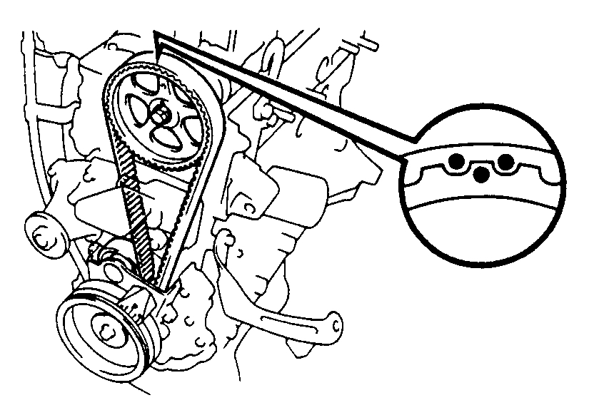
pic 47
38.Check that the crank and cam pulleys line up with there respective marks as shown, if they do not, remove the belt and reinstall.
pic 47
39.Torque the idler pulley bolt to 37 Nm (27 ft.lbs).
pic 48
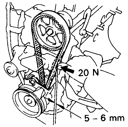
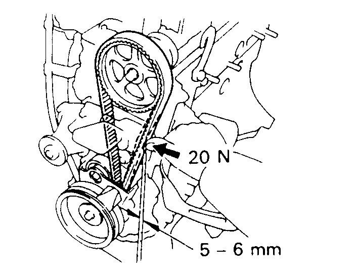
40. Check that timing belt deflection is 5 - 6 mm (0.20 - 0.24 in.) as shown. Adjust idler pulley as necessary to match spec.
pic 49
41. Install the No.2 and No.3 timing belt covers, torque to 7.4 Nm (65 in.lbs). Install spark plugs, torque to 18 Nm (13 ft.lbs).
pic 50
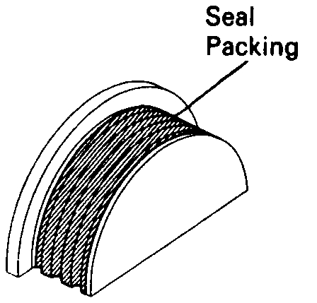
42. Remove any old packing material and apply new seal packing, part No. 08826-00080, to the circular plug as shown.
pic 51
43. Install the semi-circular plug to the cylinder head.
44. Remove any old packing material from the valve cover and cylinder head.
pic 52
45. Apply seal packing, part No. 08826-00080, to the cylinder head as shown above.
46. Install new gasket to the valve cover.
pic 53
47. Install the valve cover with the seal washers and cap nuts. Torque to 5.9 Nm (52 in.lbs).
NOTE: When using a new cylinder head, spark plug tubes must be installed.
Installing Spark Plug Tubes
pic 54
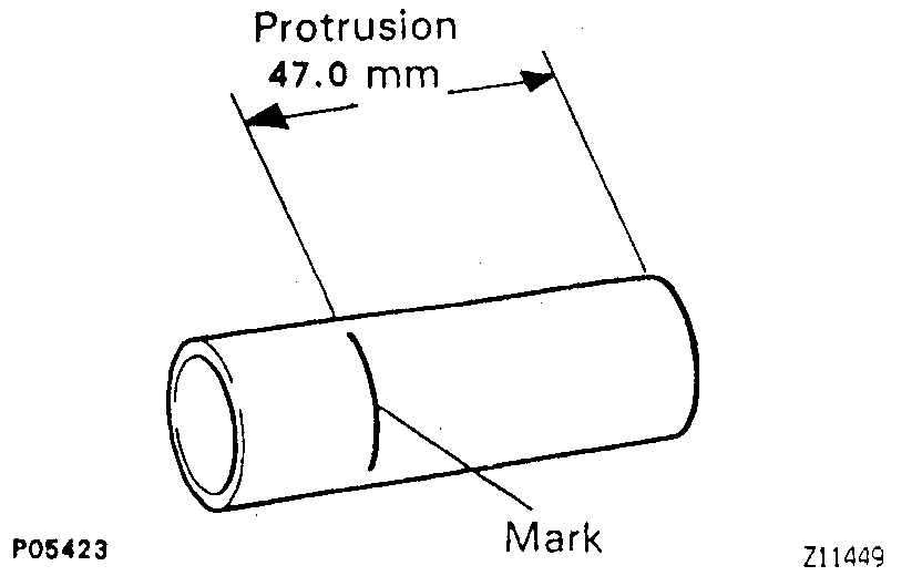
(a) Mark the standard position away from the edge, onto the spark plug tube.
Standard protrusion: 46.8 - 47.6 mm (1.843 - 1.874 inch)
pic 55
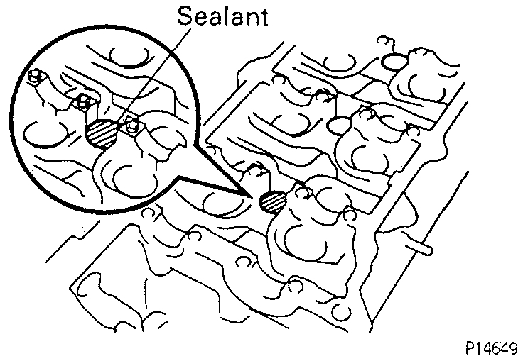
(b) Apply adhesive to the spark plug tube hole of the cylinder head.
Sealant: Part No. 08833 - 00070, Adhesive 1324, THREE BOND 1324 or equivalent.
pic 56
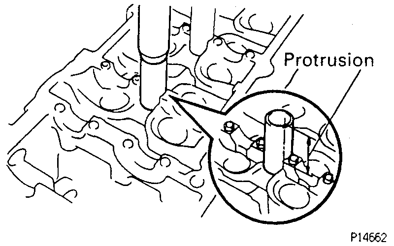
(c) Using a press, press in a new spark plug tube until there is 46.8 - 47.6 mm (1.843 - 1.874 inch) protruding from the camshaft bearing cap installation surface of the cylinder head.
CAUTION: Avoid pressing a new spark plug tube in too far by measuring the amount of protrusion while pressing.
____________________________________-__________________________________________________
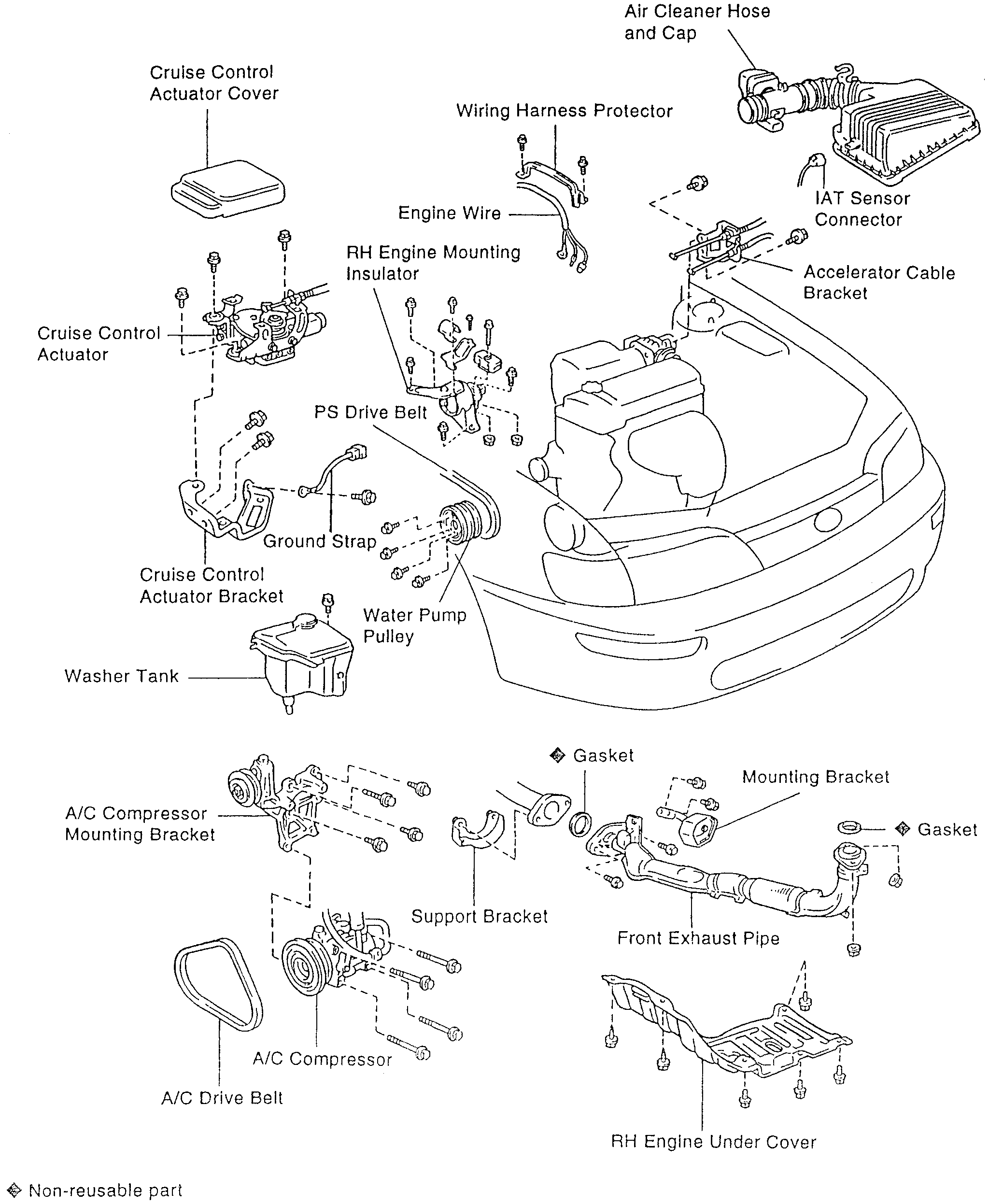
Removal 1.8L
CYLINDER HEAD REMOVAL
pics 57 to 59
SPECIAL SERVICE TOOL (SST) REQUIRED
- 09205-16010 Cylinder Head Bolt Wrench
- Or Equivalent
1. Drain engine coolant.
2. Remove RH engine under cover.
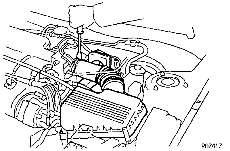
pic 60
3. Remove air cleaner hose and cap as follows:
a. Disconnect the IAT sensor connector.
b. Loosen the air cleaner hose clamp bolt.
c. Disconnect the 4 air cleaner cap clips.
d. Disconnect the air cleaner hose from the throttle body, and remove the air cleaner cap together with the air cleaner hose.
4. Disconnect accelerator cable bracket from throttle body.
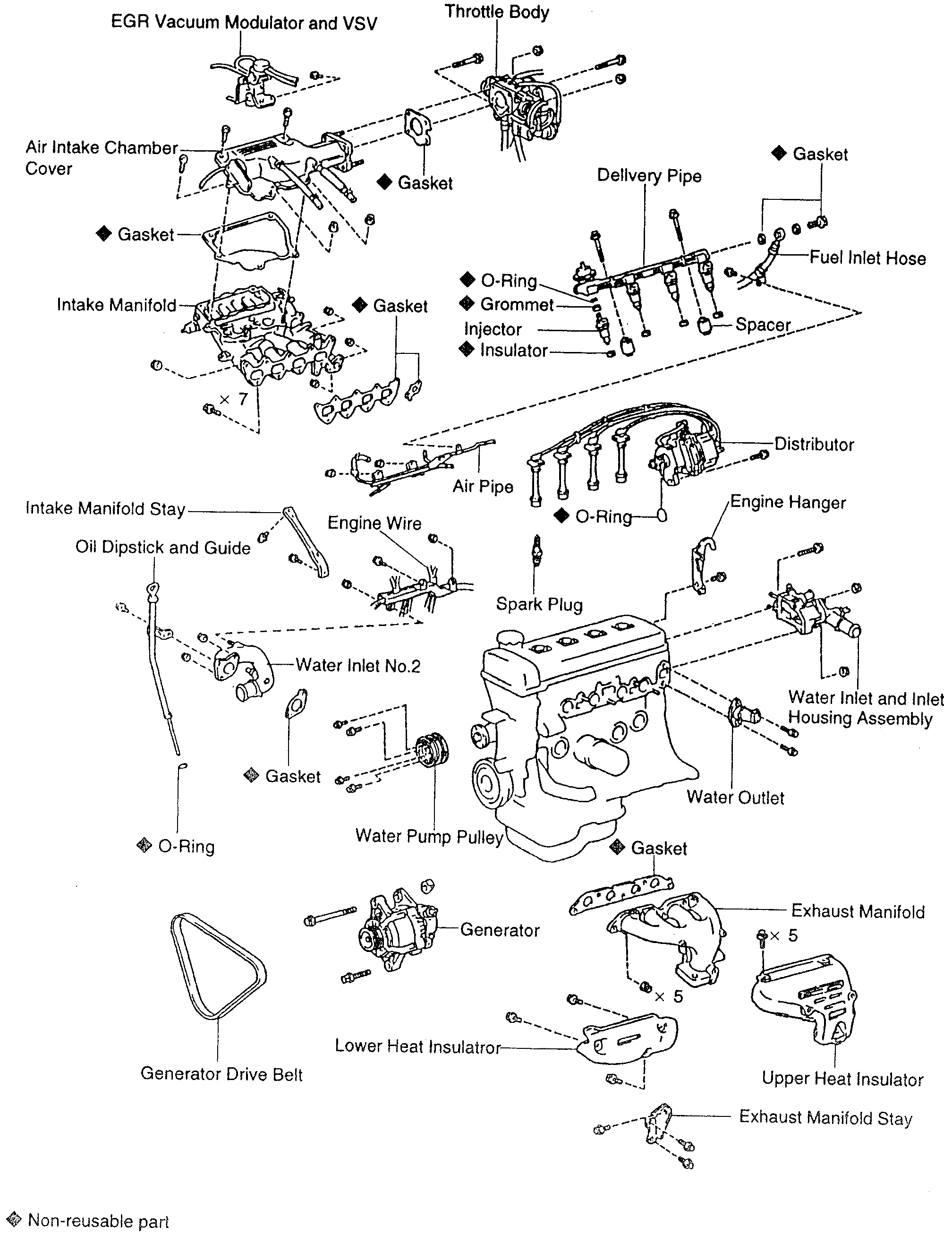
5. Remove generator. See Starting and Charging.
6. Remove distributor. See Powertrain Management.
7. Remove front exhaust pipe as follows:
a. Disconnect the oxygen sensor connector.
pic 61
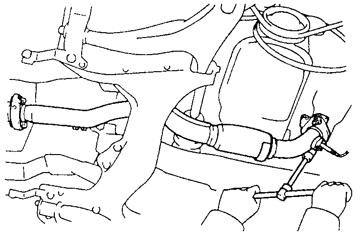
b. Remove the 2 bolts holding the front exhaust pipe to the mounting bracket.
c. Remove the 2 bolts and support bracket holding the front exhaust pipe to the TWC.
d. Using a 14 mm deep socket wrench, remove the 2 nuts.
e. Remove the front exhaust pipe and 2 gaskets.
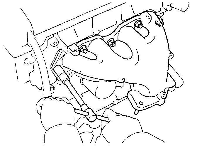
8. Remove exhaust manifold as follows:
a. Remove the 5 bolts and upper heat insulator.
b. Remove the 3 bolts and manifold stay.
pic 62
c. Remove the 5 nuts, exhaust manifold and gasket.
d. Remove the 3 bolts and lower heat insulator from the exhaust manifold.
9. Remove water outlet as follows:
a. Disconnect the radiator inlet hose from the water outlet.
pic 63
b. Remove the 2 bolts and water outlet.
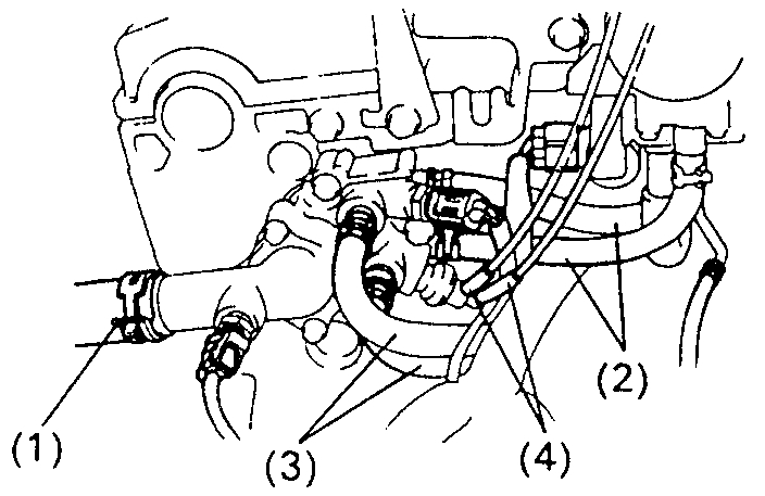
10. Remove water inlet and inlet housing as follows:
a. Disconnect the following connectors:
(1) ECT sensor connector.
(2) ECT switch connector.
(3) IAC valve connector.
pic 64
b. Disconnect the following hoses:
(1) Radiator outlet hose.
(2) Water bypass hoses.
(3) Heater water hoses.
(4) 2 EVAP TVV vacuum hoses.
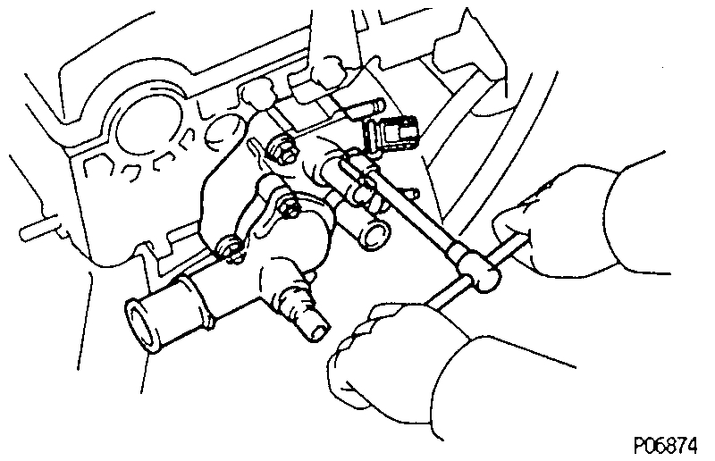
pic 65
c. Remove the bolt, 2 nuts, the water inlet and inlet housing assembly.
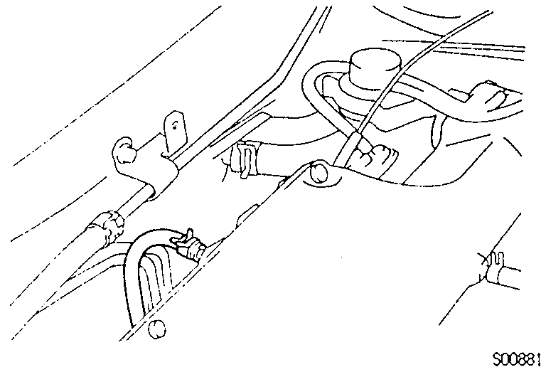
11. Disconnect ground strap connector. Disconnect the following hoses from the intake chamber:
- MAP sensor hose
- Brake booster vacuum hose
pic 66
12. Air hose from air pipe. See Steering and Suspension.
13. Remove EGR VSV
14. Remove intake manifold stay
15. Remove air pipe
16. Remove throttle body. See Powertrain Management.
17. Remove air intake chamber. See Powertrain Management.
18. Remove delivery pipe and injectors. See Powertrain Management.
19. Disconnect engine wire as follows:
a. Disconnect the following connectors:
(1) A/C compressor connector
(2) Oil pressure switch connector
(3) Crankshaft position sensor connector
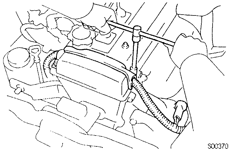
pic 67
b. Remove the 2 bolts and engine wire cover, and disconnect the engine wire from the cylinder head cover.
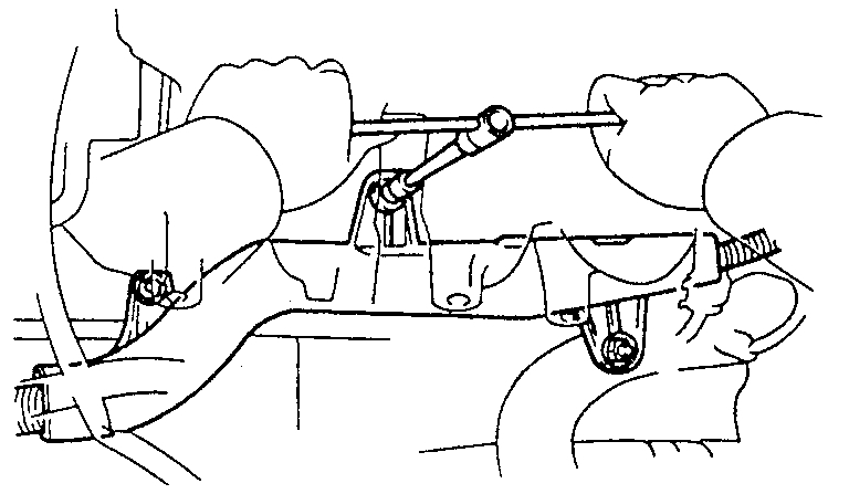
pic 68
c. Remove the bolt and 2 nuts, and disconnect the engine wire.
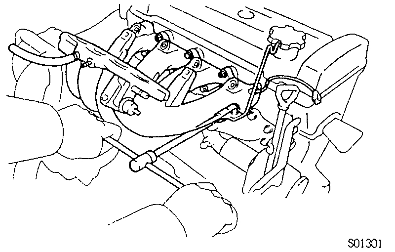
pic 69
20. Remove intake manifold. Remove the 7 bolts, 4 nuts, ground strap, intake manifold and 2 gaskets.
21. Remove RH engine mounting insulator.
22. Remove cylinder head cover Remove the 4 cap nuts, seal washers, head cover and gasket.
23. Remove spark plugs.
24. Remove No. 3 and No. 2 timing belt covers. Remove the 6 bolts, No. 3 and No. 2 timing belt covers.
pic 70
25. Set no. 1 cylinder to TDC/compression as follows:
a. Turn the crankshaft pulley and align its groove with timing mark "0" of the No. 1 timing belt cover.
b. Check that the hole of the camshaft timing pulley is aligned with the timing mark of the bearing cap. If not, turn crankshaft 1 revolution (360°).
26. Remove timing belt from camshaft timing pulley
pic 71
a. Place matchmarks on the camshaft timing pulley and belt.
b. Remove the ploy from the No. 1 timing bell cover.
c. Loosen the idler pulley mounting bolt and push the idler pulley toward the left as far as it will go, then tighten it temporarily.
pic 72
d. Remove the timing belt from the camshaft timing pulley.
CAUTION:
- Support the belt so that the meshing of the crankshaft timing pulley and timing belt does not shift.
- Be careful not to drop anything inside the timing belt cover.
- Do not allow the belt to come into contact with oil, water or dust.
pic 73
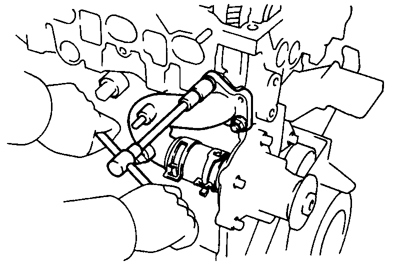
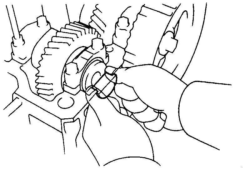
27. Remove camshaft timing pulley. Hold the hexagonal head wrench portion of the camshaft with a wrench, and remove the bolt and timing pulley.
CAUTION: Be careful not to damage the cylinder head with the wrench.
pic 74
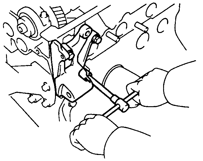
28. Remove generator bracket. Remove the 3 bolts and bracket.
pic 75
29. Remove oil dipstick guide and dipstick as follows:
a. Disconnect the crankshaft position sensor connector from the dipstick guide.
b. Remove the mounting bolt and pull out the dipstick guide and gauge.
c. Remove the O-ring from the dipstick guide.
pic 76
30. Remove water inlet No. 2. Remove the 2 nuts and water inlet from the water inlet hose.
CAUTION: Since the thrust clearance of the camshaft is small, the camshaft must be kept level while it is being removed. If the camshaft is not kept level, the portion of the cylinder head receiving the shaft thrust may crack or be damaged, causing the camshaft to seize or break. To avoid this, the following steps should be carried out.
31. Remove intake camshaft as follows:
pic 77
a. Set the exhaust camshaft so the knock pin is slightly above the top of the cylinder head.
NOTE: The above angle allows the No. 1 and No. 3 cylinder cam lobes of the intake camshaft to push their valve lifters evenly.
pic 78
b. Remove the 2 bolts and front bearing cap.
pic 79
c. Secure the intake camshaft sub-gear to the main gear with a service bolt. Recommended service bolt:
- Thread diameter: 6 mm
- Thread pitch: 1.0 mm
- Bolt length: 16-20 mm (0.63-0.79 inch)
CAUTION: When removing the camshaft, make certain that the torsional spring force of the sub-gear has been eliminated by the above operation.
pic 80
d. Uniformly loosen and remove the 8 bearing cap bolts in several passes in the sequence shown.
e. Remove the 4 bearing caps and camshaft.
pic 81
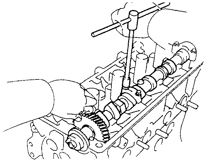
NOTE: If the camshaft is not lifted out straight and level, reinstall the No.2 bearing cap with the 2 bolts Then alternately loosen and remove the bearing cap bolts with the camshaft gear pulled up.
CAUTION: Do not pry on or attempt to force the camshaft with a tool or other object.
32. Remove exhaust camshaft as follows:
pic 82
a. Set the exhaust camshaft so the knock pin is located slightly counterclockwise from the vertical axis of the camshaft.
NOTE: The above angle allows the No. 1 and No. 3 cylinder cam lobes of exhaust camshaft to push their valve lifters evenly.
pic 83
b. Remove the 2 bolts, front bearing cap and oil seal.
CAUTION: The front bearing cap is difficult to remove, do not use a hammer and chisel as this may damage the bearing cap.
pic 84
c. Uniformly loosen and remove the 8 bearing cap bolts in several passes in the sequence shown.
d. Remove the 4 bearing caps and camshaft.
pic 85
NOTE: If the camshaft is not being lifted out straight and level, reinstall the No. 3 bearing cap with the 2 bolts. Then alternately loosen and remove the 2 bearing cap bolts with the camshaft gear pulled up.
CAUTION: Do not pry on or attempt to force the camshafts with a tool or other object.
33. Disassemble intake camshaft as follows:
a. Mount the hexagonal wrench head portion of the camshaft in a vise.
CAUTION: Be careful not to damage the camshaft.
pic 86
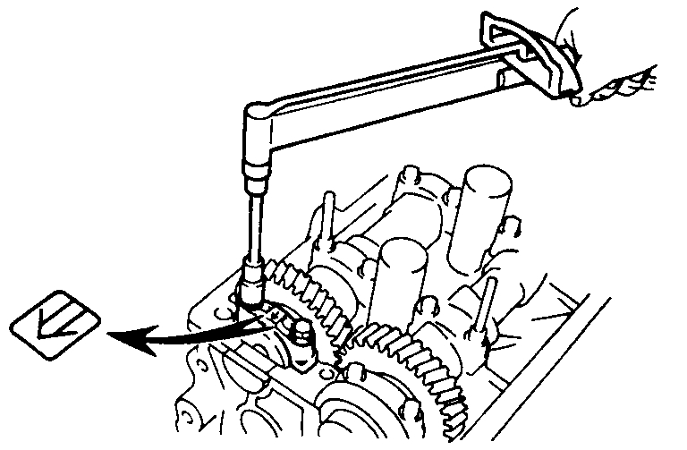
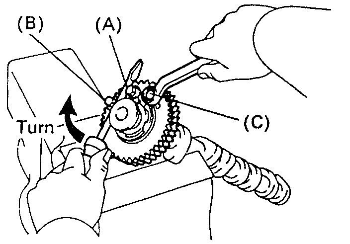
b. Insert service bolts (A) and (B) into the service holes of the camshaft sub-gear.
c. Using a screwdriver, turn the sub-gear clockwise, and remove service bolt (c).
CAUTION: Be careful not to damage the camshaft.
d. Using snap ring pliers, remove the snap ring.
pic 87
e. Remove the following parts:
(1) Wave washer.
(2) Camshaft sub-gear.
(3) Camshaft gear spring.
34. Remove semi-circular plug.
35. Remove cylinder head as follows:
pic 88
a. Using SST Cylinder Head Bolt Wrench, uniformly loosen and remove the 10 cylinder head bolts, in several passes, in the sequence shown.
CAUTION: Cylinder head warpage or cracking could result from removing bolts in incorrect order.
pic 89
b. Lift the cylinder head from the dowels on the cylinder block and place the head on wooden blocks on a bench.
CAUTION: If the cylinder head is difficult to lift off, pry with a screwdriver between the cylinder head and block saliences. Be careful not to damage the contact surfaces of the cylinder head and cylinder block.
_________________________________
1.8L Install
Cylinder Head Installation
Vehicle Engine, Cooling and Exhaust Engine Cylinder Head Assembly Service and Repair Procedures Cylinder Head Installation
CYLINDER HEAD INSTALLATION
pic 90
1. Paying close attention to the installation direction, place the new head gasket in position on the cylinder block.
2. Carefully place the cylinder head in position on the head gasket.
NOTE: Inspect the head bolts, if any are broken or deformed, replace them.
3. Apply a light coat of engine oil on the threads and under the heads of the head bolts.
pic 91
4. Using SST #09205-16010 or equivalent, torque the 10 head bolts, in several passes in the sequence shown. Torque to 29Nm (22 ft.lbs). Note that the head bolts are in two lengths. Install the shorter bolts in the intake manifold (A) side and the longer bolts in the exhaust manifold (B) side.
pic 92
5. Mark the front of the head bolts with paint as shown.
6. Torque the head bolts, in the same sequence as before, an additional 90°.
pic 93
7. Torque the head bolts an additional 90° and check that the paint mark on the head bolts now all point to the rear.
8. Apply MP grease to the thrust portion of the cam.
pic 94
9. Place the exhaust cam so the knock pin is located slightly counterclockwise from the vertical axis of the cam.
pic 95
10. Remove any old packing material and apply new seal packing, part no. #08826-00080 or equivalent, to the cylinder head as shown above.
pic 96
11. Install the 5 bearing caps in their proper location.
12. Apply a light coat of engine oil on the threads and under the heads of the bearing cap bolts.
pic 97
13. Install and uniformly torque the 10 cap bolts, in several passes, to 13Nm (9 ft.lbs) following the sequence shown above.
pic 98
14. Apply MP grease to the new oil seal lip.
pic 99
15. Using SST #09223-46011 or equivalent, carefully tap the oil seal into place.
Caution: Do not install the oil seal with lip facing the wrong direction and make sure to insert the oil seal into the deepest part of the cylinder head.
pic 100
16. Set the exhaust cam so that the knock pin is slightly above the top of the cylinder head.
17. Apply MP grease to the thrust portion of the cam.
pic 101
18. Engage the intake cam gear to the exhaust cam gear by matching the assembly installation marks on each gear
Caution: There are also timing marks (for TDC) on each gear as shown in the image above. Do NOT use these marks.
19. Roll down the intake cam onto the bearing journals while engaging gears with each other.
pic 102
20. Install the 4 bearings caps in their proper locations.
21. Apply a light coat of engine oil on the threads and under the heads of the bearing cap bolts.
pic 103
22. Install and uniformly torque the 8 bearing cap bolts, in several passes, to 13Nm (9 ft.lbs) in the sequence shown above.
pic 104
23. Remove the service bolt (C).
pic 105
24. Install the No.1 bearing cap with the arrow mark facing forward. If the No.1 cap does not fit properly, very carefully push the cam gear backwards using a screwdriver to pry between the head and the cam gear.
25. Apply a light coat of engine oil on the threads and under the heads of the bearing cap bolts.
26. Install and alternately tighten the 2 bolts in several passes. Torque to 13Nm (9 ft.lbs).
pic 106
27. Turn the exhaust cam clockwise and set it with the knock pin facing upward as shown.
pic 107
28. Check that the timing marks of the cam gears are aligned and the installation marks are up.
29. Check and adjust valve clearance as necessary.
30. Connect the water inlet to the water inlet hose.
pic 108
31. Install the water inlet with the 2 nuts. Torque to 15 Nm (11 ft.lbs).
32. Push in the oil dipstick guide with the new O-ring coated with a small amount of engine oil.
pic 109
33. Install the mounting bolt and torque to 9Nm (82 in.lbs). Insert the oil dipstick.
pic 110
34. Install the generator bracket with the three bolts. Torque to 26 Nm (20 ft.lbs).
pic 111
35. Install the engine hanger with the mount bolt and torque to 27 Nm (20 ft.lbs).
36. Install the cam timing pulley.
pic 112
37. Align the matchmarks made during removal of the timing belt and cam timing pulley.
38. Remove any oil or water on the cam timing pulley and keep it clean.
pic 113
39. Install the timing belt, checking the tension between the crank pulley and the cam pulley.
pic 114
40. Loosen the idler pulley bolt 1/2 turn.
pic 115
41. Turn the crank pulley 2 revolutions, clockwise only, from TDC to TDC.
pic 116
42. Check that each pulley aligns with the timing marks as shown, if not remove the timing belt and reinstall.
pic 117
43. Torque the idler pulley bolt to 37Nm (27 ft.lbs).
pic 118
44. Check that the belt tension, at the position indicated in the image above, is 5-6mm at 20N force.
pic 119
45. If not as specified adjust with the idler pulley.
pic 120
46. Install the No.2 and No.3 timing belt covers with the 6 bolts and torque to 7.4Nm (65 in.lbs).
47. Install spark plugs and torque to 18Nm (13 ft.lbs).
48. Remove any old packing material from the cylinder head.
49. Apply seal packing, part no. 08826-00080 or equivalent, to the half-moon seal.
pic 121
50. Install the half-moon seal to the cylinder head.
pic 122
51. Apply seal packing, part no. 08826-00080 or equivalent, to the cylinder head as shown above.
52. Install the new gasket to the valve cover.
pic 123
53. Install the valve cover with the cap nuts and new seal washers. Torque to 5.9Nm (52 in.lbs).
_________________________________________________
I know this is a lot, but I had to add for both engines. Let me know if you have questions or need help.
Take care,
Joe
Images (Click to enlarge)
Apr 15, 2019 at 7:37 PM