Good evening.
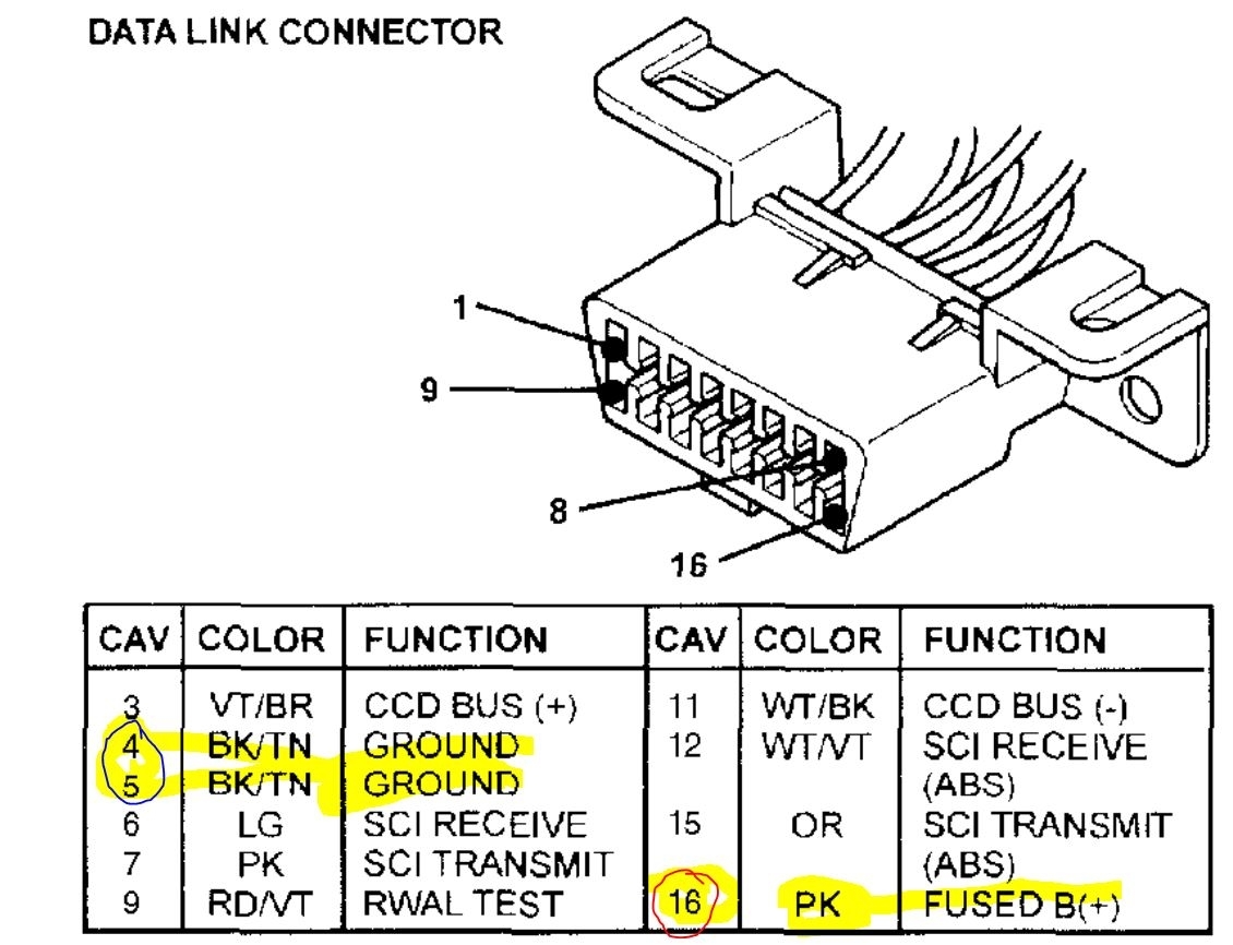
There is a communication bus line from the data link connector that could be the issue or it could be the PCM. They need to be checked. Below is the description and testing.
Roy
VEHICLE COMMUNICATION
CCD Data Bus
The Chrysler Collision Detection (also referred to as CCD or C2D ) data bus system is a multiplex system used for vehicle communications on many Chrysler Corporation vehicles. Within the context of the CCD system, the term "collision" refers to the system's ability to avoid collisions of the electronic data that enters the data bus from various electronic control modules at approximately the same time.
Multiplexing is a system that enables the transmission of several messages over a single channel or circuit. Many Chrysler vehicles use this principle for communication between the various microprocessor-based electronic control modules.
Many of the electronic control modules in a vehicle require information from the same sensing device. In the past, if information from one sensing device was required by several controllers, a wire from each controller needed to be connected in parallel to that sensor. In addition, each controller utilizing analog sensors required an Analog/Digital (A/D) converter in order to "read" these sensor inputs. Multiplexing reduces wire harness complexity, sensor current loads and controller hardware because each sensing device is connected to only one controller, which reads and distributes the sensor information to the other controllers over the data bus. Also, because each controller on the data bus can access the controller sensor inputs to every other controller on the data bus, more function and feature capabilities are possible.
In addition to reducing wire harness complexity, component sensor current loads and controller hardware, multiplexing offers a diagnostic advantage. A multiplex system allows the information flowing between controllers to be monitored using a diagnostic scan tool. The Chrysler system allows an electronic control module to broadcast message data out onto the bus where all other electronic control modules can "hear" the messages that are being sent. When a module hears a message on the data bus that it requires, it relays that message to its microprocessor. Each module ignores the messages on the data bus that are being sent to other electronic control modules.
With a diagnostic scan tool connected into the CCD circuit, a technician is able to observe many of the electronic control module function and message outputs while; at the same time, controlling many of the sensor message inputs. The CCD data bus, along with the use of a diagnostic scan tool and a logic- based approach to test procedures, as found in the Diagnostic Procedures, allows the trained automotive technician to more easily, accurately and efficiently diagnose the many complex and integrated electronic functions and features found on today's vehicles.
The CCD data bus system was designed to run at a 7812.5 baud rate (or 7812.5 bits per second). In order to successfully transmit and receive binary messages over the CCD data bus, the system requires the following:
- Bus (+) and Bus (-) Circuits
- CCD Chips in Each Electronic Control Module
- Bus Bias and Termination
- Bus Messaging
- Bus Message Coding
The Chrysler Collision Detection multiplex system (CCD) consists of a twisted pair of wires. These wires run from one module to another. They receive and deliver coded information between the modules. The information is coded to identify the message as well as the importance of the message. When there are multiple messages trying to access the CCD bus at one time, the code determines the message that has the higher priority, and is then allowed to access the bus first.
The two wires of the twisted pair that make up the CCD multiplex system are called "bus +" (bus plus) and "bus -" (bus minus) respectively. Each wire has a measurable voltage level of roughly 2.5 Volts. In order to maintain the 2.5 Volts on each line and provide a means of transportation for the coded messages, there is a voltage divider network located in the module that supplies bus bias or voltage. Along with the module that supplies bias, some modules provide termination. Bias is the voltage necessary to make the bus operational. At least one point of termination is necessary, some systems use more than one. Some modules are capable of biasing and terminating the bus by themselves. Termination in the circuitry (a 120 ohm resistor placed across the bus) is required to complete the voltage divider network circuit and also provide some electromagnetic protection for the bus. Without termination, voltage on the bus goes to approximately 5 Volts on one wire and 0 Volts on the other wire. In the 2001 Ram Truck, the instrument cluster supplies bus bias and termination and the PCM supplies and additional point of termination.
NOTE: COMMUNICATION OVER THE BUS IS ESSENTIAL TO THE PROPER OPERATION OF THE VEHICLES ON-BOARD DIAGNOSTIC SYSTEMS AND THE DRB III. PROBLEMS WITH THE OPERATION OF THE BUS OR THE DRB III MUST BE CORRECTED BEFORE PROCEEDING WITH DIAGNOSTIC TESTING. IF THERE IS A PROBLEM, REFER TO THE VEHICLE COMMUNICATIONS.
Bus (+) And Bus (-) Circuits
The two wires (sometimes referred to as the "twisted pair") that comprise the CCD data bus are the D1 circuit [Bus (+)], and the D2 circuit [Bus (-)]. The "D" in D1 and D2 identify these as diagnostic circuits. Transmission and receipt of binary messages on the CCD data bus is accomplished by cycling the voltage differential between the Bus (+) and Bus (-) circuits.
The two data bus wires are twisted together in order to shield the wires from the effects of any Electro-Magnetic Interference (EMI) from switched voltage sources. An induced EMI voltage can be generated in any wire by a nearby switched voltage or switched ground circuit. By twisting the data bus wires together, the induced voltage spike (either up or down) affects both wires equally. Since both wires are affected equally, a voltage differential still exists between the Bus (+) and Bus (-) circuits, and the data bus messages can still be broadcast or received. The correct specification for data bus wire twisting is one turn for every 44.45 millimeters (1 3/4 inches) of wire.
Fig.5 CCD Chip
imageZoom/Print
CCD Chips
In order for an electronic control module to communicate on the CCD data bus, it must have a CCD chip. The CCD chip contains a differential transmitter/receiver (or transceiver), which is used to send and receive messages. Each module is wired in parallel to the data bus through its CCD chip.
The differential transceiver sends messages by using two current drivers: one current source driver, and one current sink driver. The current drivers are matched and allow 0.006 ampere to flow through the data bus circuits. When the transceiver drivers are turned ON, the Bus (+) voltage increases slightly, and the Bus (-) voltage decreases slightly. By cycling the drivers ON and OFF, the CCD chip causes the voltage on the data bus circuit to fluctuate to reflect the message.
Once a message is broadcast over the CCD data bus, all electronic control modules on the data bus have the ability to receive it through their CCD chip. Reception of CCD messages is also carried out by the transceiver in the CCD chip. The transceiver monitors the voltage on the data bus for any fluctuations. When data bus voltage fluctuations are detected, they are interpreted by the transceiver as binary messages and sent to the electronic control module's microprocessor.
Bus Bias And Termination
The voltage network used by the CCD data bus to transmit messages requires both bias and termination. At least one electronic control module on the data bus must provide a voltage source for the CCD data bus network known as bus bias, and there must be at least one bus termination point for the data bus circuit to be complete. However, while bias and termination are both required for data bus operation, they both do not have to be within the same electronic control module. The COD data bus is biased to approximately 2.5 volts. With each of the electronic control modules wired in parallel to the data bus, all modules utilize the same bus bias. Therefore, based upon vehicle options, the data bus can accommodate two or twenty electronic control modules without affecting bus voltage.
Fig.6 Bus Biasing
imageZoom/Print
Fig.7 Bus Termination
imageZoom/Print
The power supplied to the data bus is known as bus biasing. Bus bias is provided through a series circuit. To properly bias the data bus circuits, a 5 volt supply is provided through a 13 kiloohm resistor to the Bus (-) circuit. Voltage from the Bus (-) circuit flows through a 120 ohm termination resistor to the Bus (+) circuit. The Bus (+) circuit is grounded through another 13 kiloohm resistor. While at least one termination resistor is required for the system to operate, most Chrysler systems use two. The second termination resistor serves as a backup. The termination resistor provides a path for the bus bias voltage. Without a termination point, voltage biasing would not occur. Voltage would go to 5 volts on one bus wire and 0 volts on the other bus wire.
The voltage drop through the termination resistor creates 2.51 volts on Bus (-), and 2.49 volts on Bus (+). The voltage difference between the two circuits is 0.02 volts. When the data bus voltage differential is a steady 0.02 volts, the CCD system is considered "idle." When no input is received from any module and the ignition switch is in the OFF position for a pre-programmed length of time, the bus data becomes inactive or enters the "sleep mode." Electronic control modules that provide bus bias can be programmed to "wake up" the data bus and become active upon receiving any predetermined input or when the ignition switch is turned to the ON position.
Bus Messaging
The electronic control modules used in the CCD data bus system contain microprocessors. Digital signals are the means by which microprocessors operate internally and communicate messages to other microprocessors. Digital signals are limited to two states, voltage high or voltage low, corresponding to either a one or a zero. Unlike conventional binary code, the COD data bus systems translate a small voltage difference as a one (1), and a larger voltage difference as a zero (0). The use of the 0 and 1 is referred to as binary coding. Each binary number is called a bit, and eight bits make up a byte. For example: 01011101 represents a message. The controllers in the multiplex system are able to send thousands of these bytes strung together to communicate a variety of messages. Through the use of binary data transmission, all electronic control modules on the data bus can communicate with each other.
The microprocessors in the COD data bus system translate the binary messages into Hexadecimal Code (or Hex Code). Hex code is the means by which microprocessors communicate and interpret messages. When fault codes are received by the DRB III scan tool, they are translated into text for display on the DRB III screen. Although not displayed by the DRB III for Body Systems, hex codes are shown by the DRB III for Engine System faults.
Fig.8 Voltage Cycling To Correspond To Message
imageZoom/Print
When the microprocessor signals the transceiver in the CCD chip to broadcast a message, the transceiver turns the current drivers ON and OFF, which cycles the voltage on the CCD data bus circuits to correspond to the message. At idle, the CCD system recognizes the 0.02 voltage differential as a binary bit 1. When the current drivers are actuated, the voltage differential from idle must increase by 0.02 volt for the CCD system to recognize a binary bit 0. The nominal voltage differential for a 0 bit is 0.100 volts. However, data bus voltage differentials can range anywhere between 0.02 and 0.120 volt.
Bus Message Coding
The first part of a data bus message has an Identification (ID) byte. The ID byte contains message priority, message identification, message content and message length information. All messages sent over the data bus are coded for both priority and identification.
Priority
Messages can be broadcast almost simultaneously by modules over the CCD data bus. Therefore, all messages are defined and ranked by a predetermined priority. When two CCD chips start a message at exactly the same time, non-destructive arbitration occurs between the two CCD chips. Arbitration will occur based upon the priority code, to determine which message takes priority on the data bus and to prevent data collision. If a CCD chip senses a message of higher priority being transmitted, it stops transmitting its message. The higher priority message is then transmitted in its entirety without interruption. The other CCD chips on the data bus do not allow any other messages to be broadcast.
Fig.9 Message Arbitration
imageZoom/Print
To determine the winner in an arbitration, all messages start with an ID byte which contains the predetermined priority code. In the digital broadcast, zero is the dominant bit. All ID bytes start with a zero. This is the start of the message. With zeros being the dominant bit, messages starting with more zeros have a higher priority. For example: of the two messages below, Message # 2 loses arbitration at the second bit, where Message # 1 has a zero and Message # 2 has a one. After the message is broadcast, an idle period occurs while all microprocessors can queue, if necessary, and attempt to broadcast their messages again.
- Message # 1 = 00010110
- Message # 2 01010101
Message Identification
Because messages are broadcast over the data bus, all modules can receive them, yet not all modules need all messages. In order to enhance microprocessor speed, unneeded messages are filtered out. The ID byte, along with showing message priority, also identifies the data, content and length. The electronic control module, through its CCD chip transceiver, monitors the ID code of the messages. If the message is not for that particular module, the message is simply ignored. Once the module recognizes a message that it requires, the rest of the message is monitored and processed.
Transmission Verification
Once a CCD chip transmits a message over the CCD data bus, the message is received by the transmitting module at the same time through the CCD chip differential transceiver. The module knows the message was broadcast correctly when it receives its own message back. If the message received does not match the message transmitted, the message is said to be corrupt.
Corruption occurs when the message is incorrectly transmitted on the data bus. Corruption can also occur from interference, wiring problems, or other data bus problems. In the case of a corrupt message,the module attempts to have the CCD chip re-send the message.
Bus Failure Messages
Short to Battery - Either or both of the bus wires are shorted to a battery potential, or a specific ground circuit may be open.
Short to 5 Volts - Either or both of the bus wires are shorted to a 5-Volt potential.
Short to Ground - Either or both of the bus wires are shorted to ground.
Bus (+) & Bus (-) Shorted Together - The two bus wires are shorted together.
No Termination - The bus system has lost connection with all of its terminators. The Instrument Cluster (MIC) and the Powertrain Control Module (PCM) supply termination for the 2001 Ram Trucks.
Bus Bias Level Too Low - Either or both of the bus wire potentials are significantly below their normal 2.5 Volts.
Bus Bias Level Too High - Either or both of the bus wire potentials are significantly above their normal 2.5 Volts.
No Bus Bias - The bus system has lost connection with all modules that provide bias. The Instrument Cluster (MIC) provides the CCD bus bias for the 2001 Ram Trucks.
Bus (+) Open - The bus (+) wire has lost connection with termination and/or bias.
Bus (-) Open - The bus (-) wire has lost connection with termination and/or bias.
Not receiving Bus Messages correctly - The DRB cannot communicate over the bus and does not know why.
Jul 17, 2018 at 4:21 PM