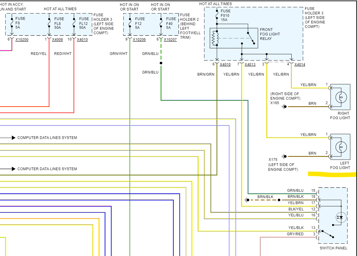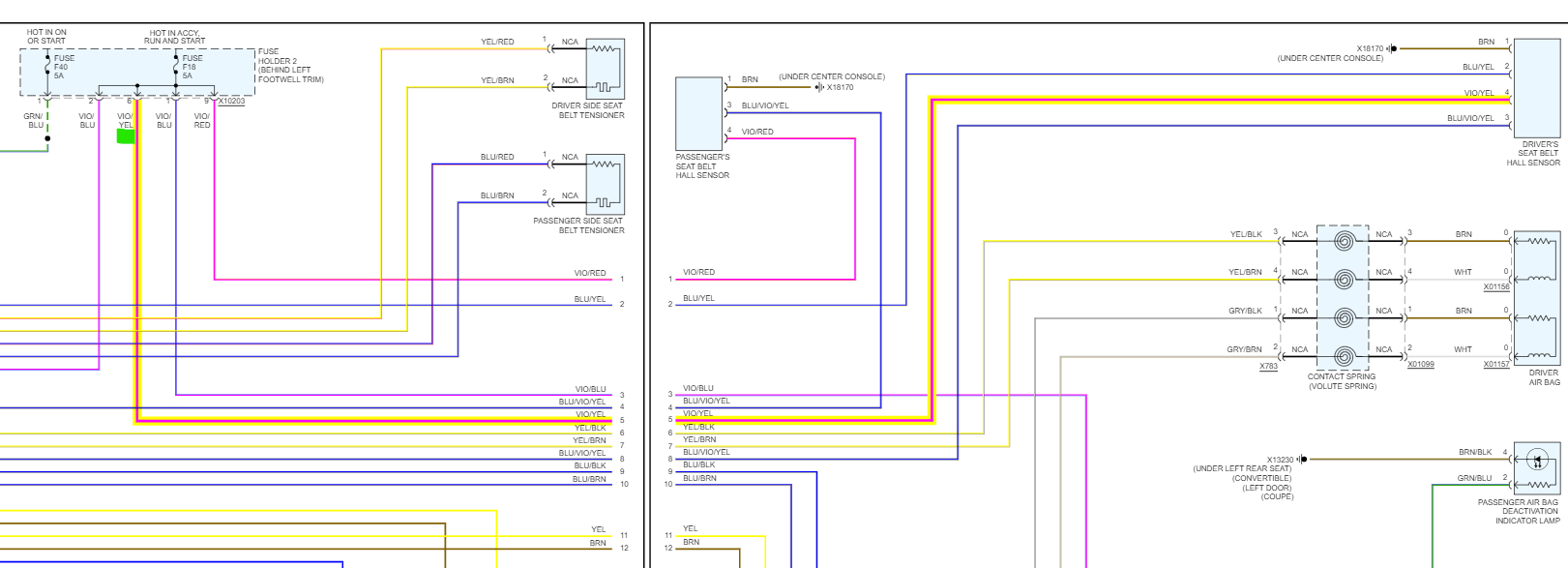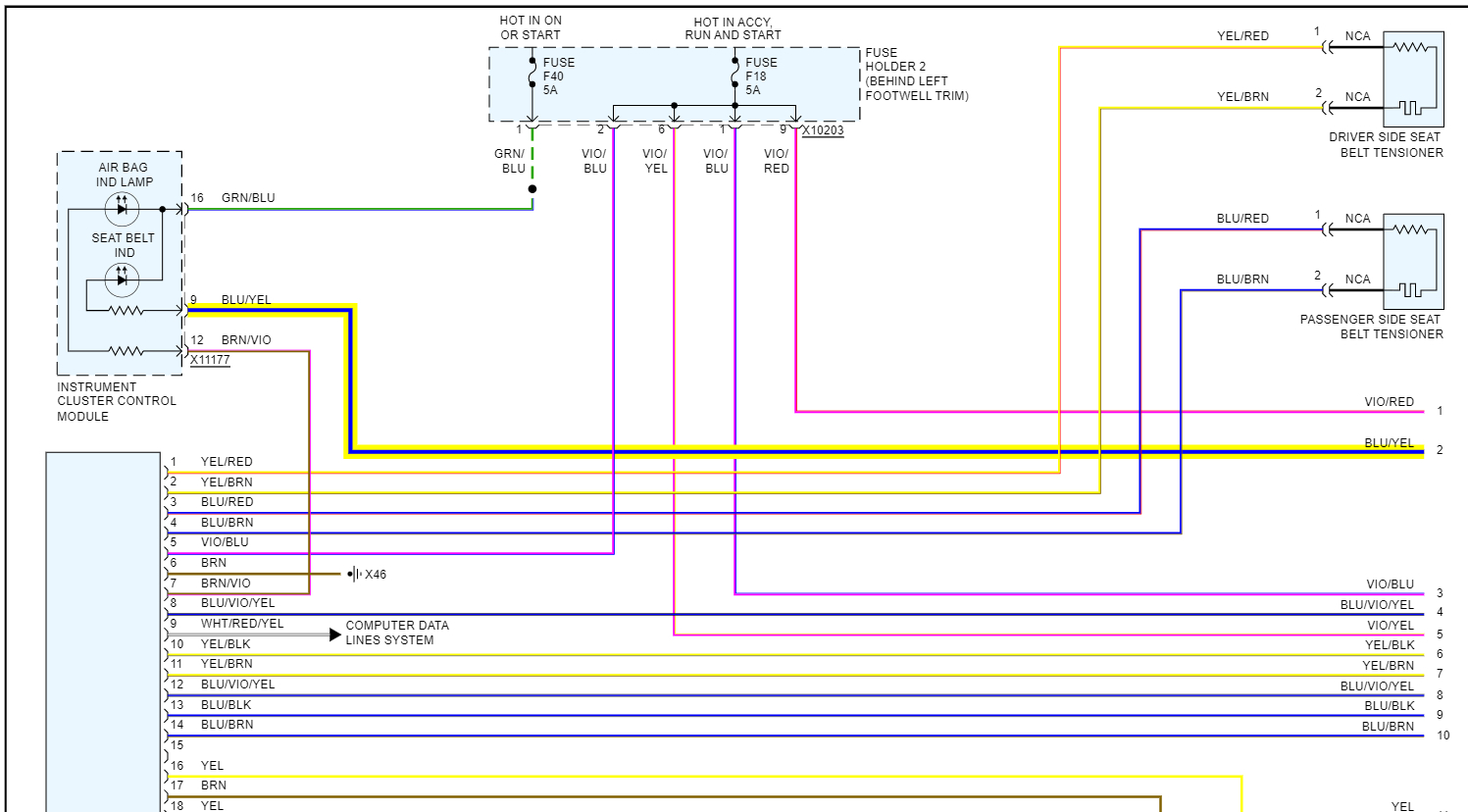
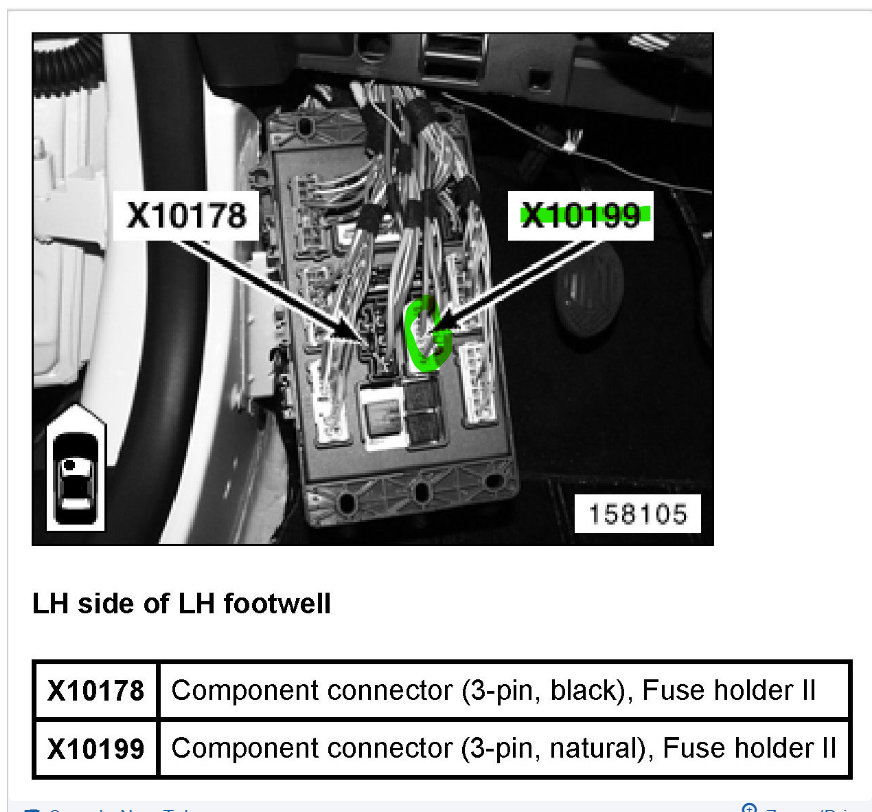
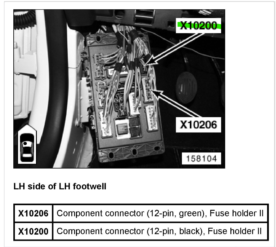
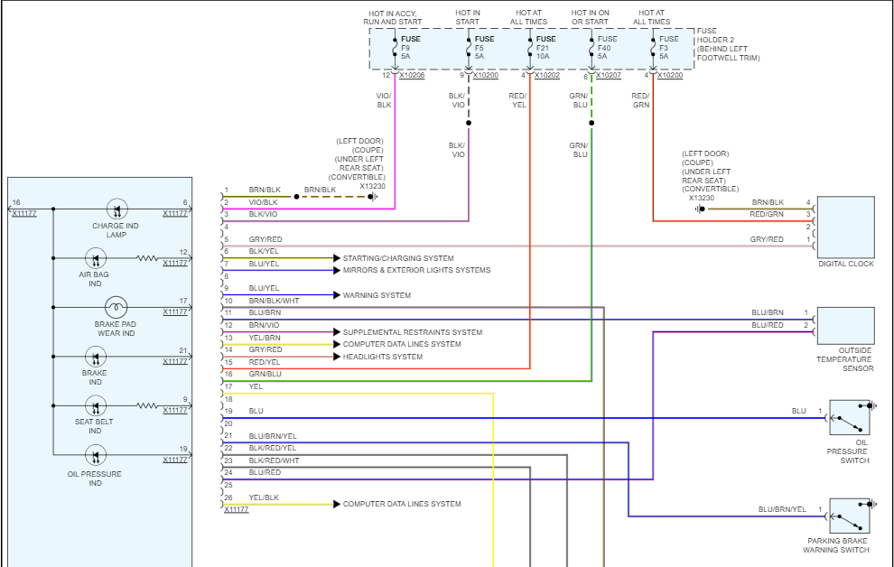
But only for F5 right now, you can see in the first diagram it comes in on X10199 and goes right out X10200.
It even shows you the wire color it should be, so black wire with yellow stripe (x10199) and then a Black wire w Violet stripe (x10200). So, you could find those specific wires on those connectors and check them for power. That will tell you if the power is being lost in the Fuse panel (Fuse Holder 2) or if the power is not even getting to the fuse panel.
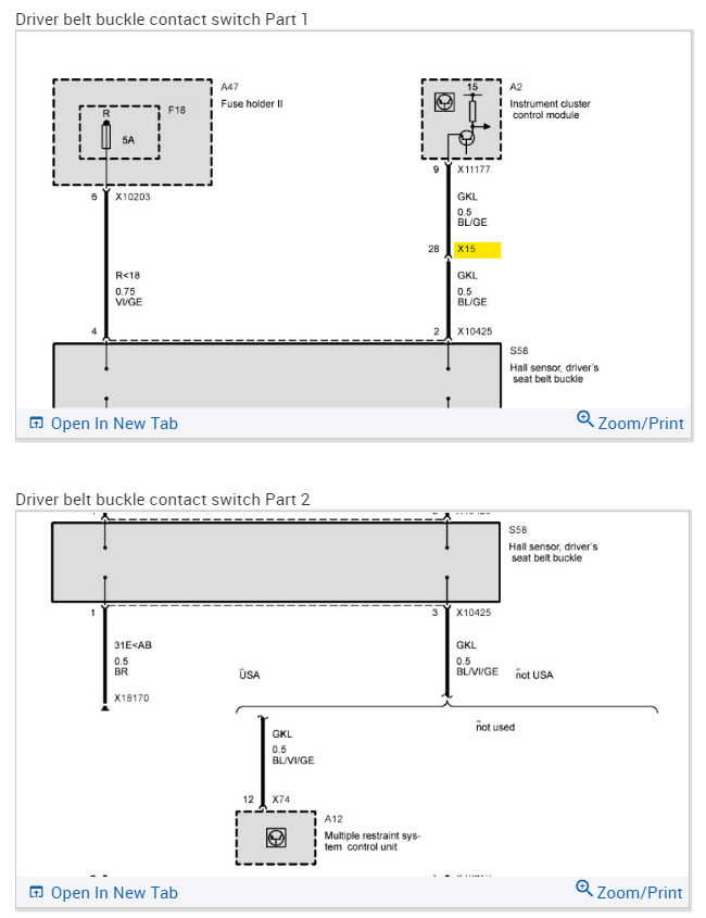
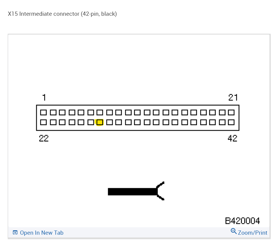
I've been trying to find a pinout of X15 for hours and just can't seem to, if you can ID the pin that broke and the two wires in connects together, if this was my car, I'd just bypass the connector, but you have to be used to doing electrical work on vehicles. I mean it's only a connector and it's full of corrosion. I would cut the two wires and crimp them together with a heat shrink connector and be done with it. Just do one at a time so you don't get mixed up.
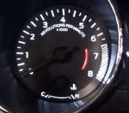
I'm not sure you'll be able to find one of those connectors, maybe a dealership, or like you said a used parts lot. I'm not sure how many you have in your area. Now that a pin is broken, it has to be fixed, but our main concern is getting you through inspection first. They will probably fail you if there's no Tach lighting.
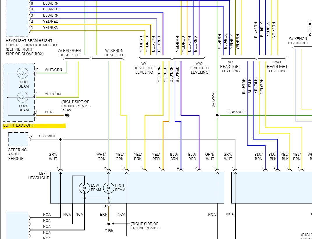
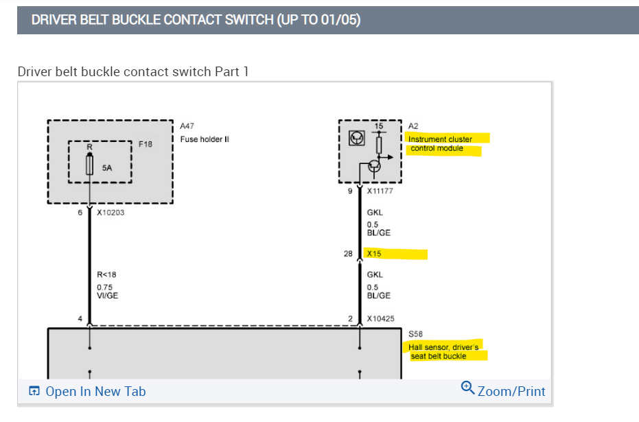
So far I've found that X15 is for the Instrument Cluster control module, but they don't give any information on it.
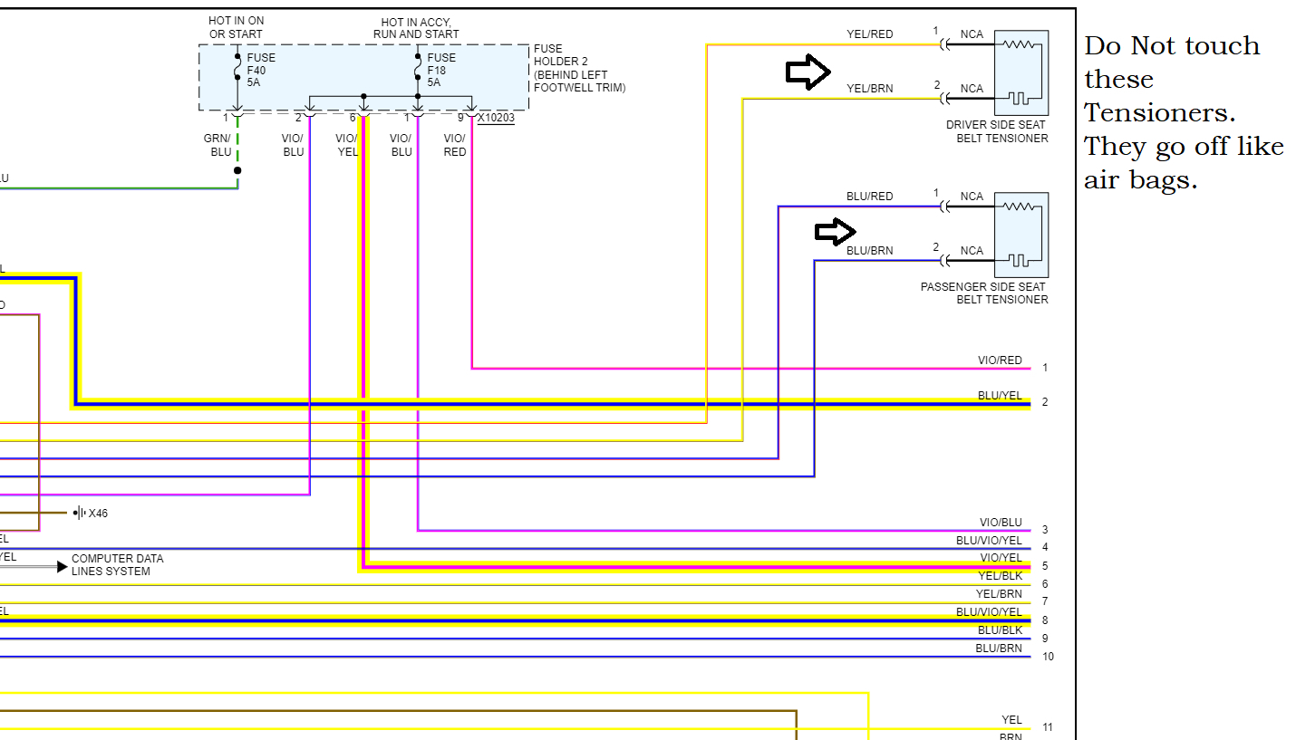
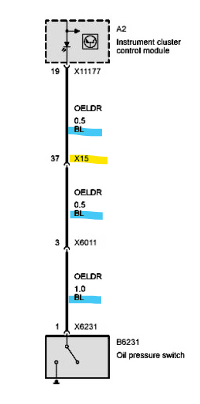
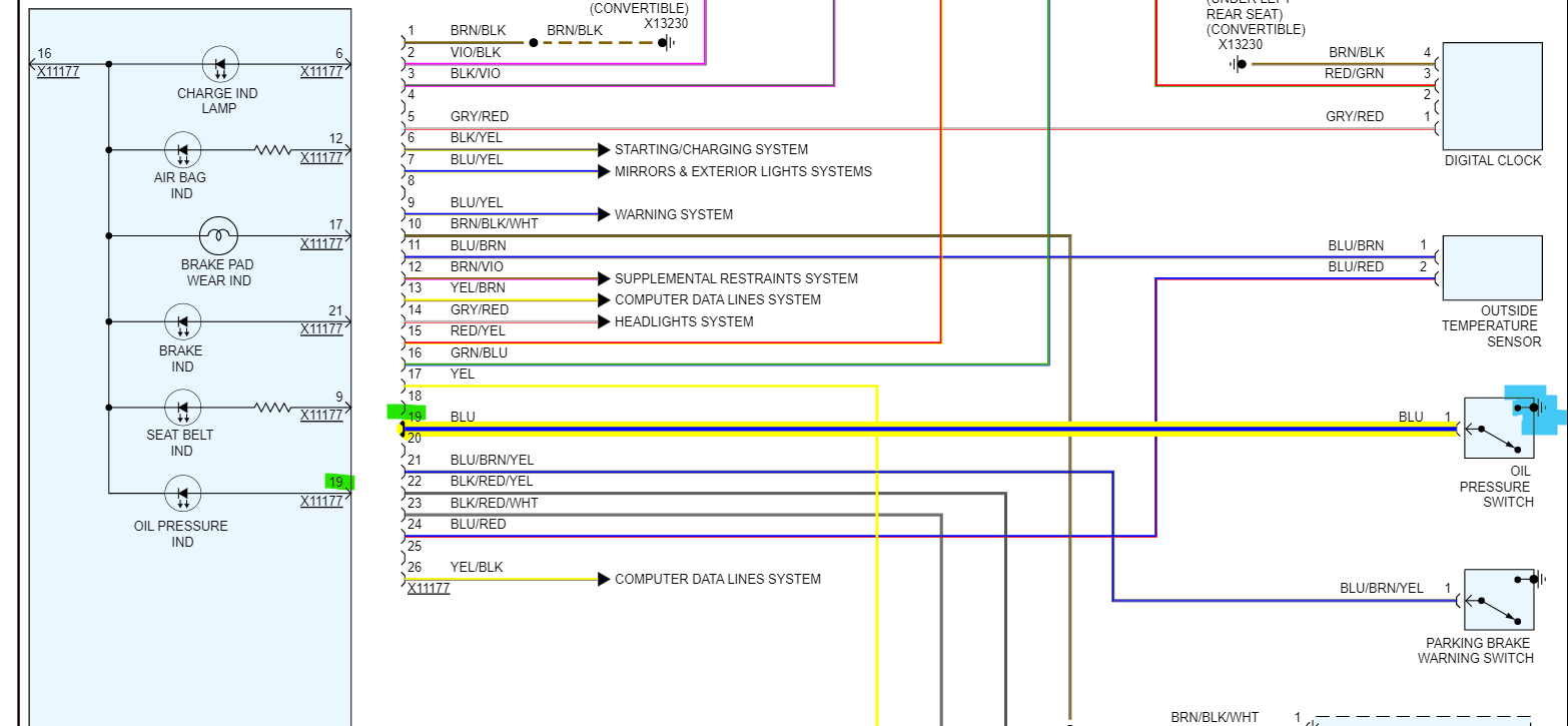
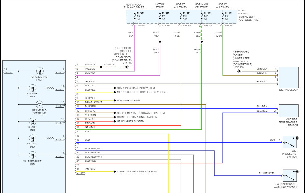
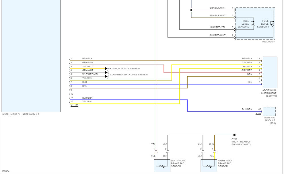
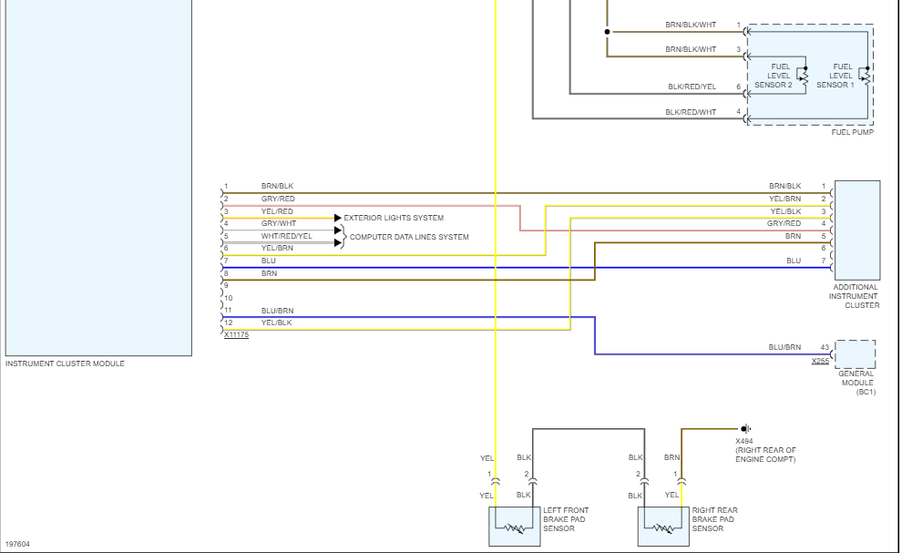
For the Cluster (diagrams 4 and 5) you can see they don't give us barely anything. It shows the connector and wires to it but doesn't show anything about the Cluster at all. There's no Tach listed, so I couldn't even tell you which wire it was on.
So, it really just depends on what you want to fix first, let's concentrate on one area to get repaired, then we'll move on, instead of jumping around.
Images (Click to make bigger)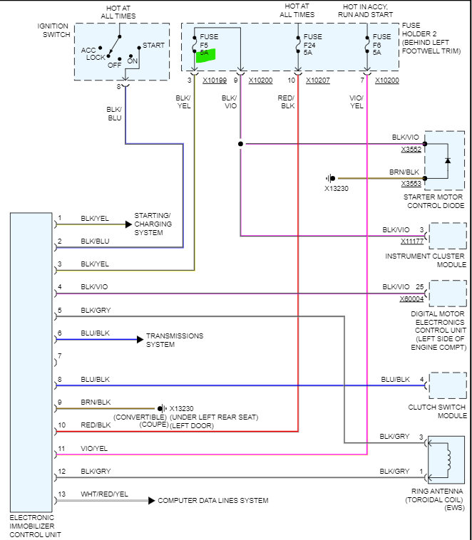


Was this helpful?
Yes
No
Thursday, August 11th, 2022 AT 11:16 AM