No Spark, no start, new distributor

Tiny
CARADIODOC
  • MECHANIC
  • 33,754 POSTS
With your system, the Engine Computer uses two separate terminals to turn the relays on, one for the ASD relay and one for the fuel pump, but they should both turn on at the same time. That is for one second when the ignition switch is turned on, then again when the engine is rotating. You can usually hear the hum of the fuel pump for that one second, but not during cranking because the starter motor is too loud. Anyway, if you hear the hum for that first one second, the fuel pump, its circuitry, and the relay are working.

I'm worried there is still some confusion about the cam and crank sensors. In your first sentence, you said, "We know the vCard computer is turning the asd on for both cam and crank sensors".

Think of a crossing guard at a grade school. The guard holds up his hands, then sees the cars come to a stop. That is the signal that tells him to motion the kids to cross the road. When you say, "turning the asd on FOR both cam and crank sensors", I'm worried you're equating that to the crossing guard's purpose for being there is to stop cars. It's not. His purpose is to know when to let kids cross the road, and he knows that by seeing the cars have stopped. The Engine Computer's job is to turn on the ASD and fuel pump relays, and it knows when to do that by observing there are signals showing up from those sensors.

Once the computer has turned on those two relays, we're way past the cam and crank sensors. They're working and don't get any more attention from us. Now we have to look at what the ASD relay powers up; in this case the ignition coils and injectors. You found 12 volts way back earlier at one of the injectors, during cranking. That proved the computer turned on the ASD relay, and that proved we're getting signal pulses from both sensors. Since we know the sensors are working, their pulses are also used to tell the computer exactly when to fire an injector and an ignition coil. We're supposed to be getting injector pulses and spark from the ignition coil, but we're missing spark. Injector pulses are harder to tell. It works best to use a special "noid" light, but few of us have them. I never invested in them because there is so little need of them.

Once both sensor signals are showing up at the computer, it is usually pretty good about firing the ignition coil. That circuitry is quite robust and has a real low failure rate. In your model, however, that high-stress circuit is moved to inside the distributor where it sits right next to the ignition coil. Because it is a high-stress circuit that uses high-power transistors, it is a real good candidate for failure, even when it's brand new. That's why, from everything we've figured out so far, while I never want to believe a new part can be bad, that is what it looks like.
Was this
answer
helpful?
Yes
No
Friday, January 26th, 2018 AT 6:48 PM
Tiny
PEGGIESEBRING
  • MEMBER
  • 17 POSTS
I didnt get oppurtunity to work on car today.
Before I contact am autoparts about a bad distributor I want to check the pulse at injectors. Sinse I don't have a test light with me I am gonna go ahead and buy a noid light. To do test

The fuel pump and its circuit do seem to be working properly still I have a question about the pump not working when the crankshaft sensor signal has taken over for cam sensor signal I raised backseat so to be able to feel the vibration of pump and for sure it works initially for one second when switch is on but then does not work during cranking but does come back on for one second when turning switch off
Lastly is there a way to test the ignition module I believe that's what you called it inside nee distributor that you feel is bad ?
Was this
answer
helpful?
Yes
No
Saturday, January 27th, 2018 AT 6:41 PM
Tiny
CARADIODOC
  • MECHANIC
  • 33,754 POSTS
I've never found anyone who knows if the ignition module can be tested, and you'll almost always find the only way to get it is to buy the distributor.

I'm trying to find a classroom manual for your engine. For the domestic version, if the fuel pump doesn't turn on again during cranking, there won't be spark or injector pulses either. Since you have the 12 volts from the ASD relay turning on during cranking, you should be missing spark, injector pulses, OR fuel pump, but not all three. Your observation proves the fuel pump is working, and even when it doesn't resume running, there's enough volume and pressure in the line for the engine to run for a few seconds. We aren't even getting that, so we have to missing spark or injector pulses.

What I'm questioning is on the domestic engine, signal pulses are needed from both the cam and crank sensors for the computer to turn on the ASD relay. Many newer engines need only one sensor to work for spark, and both sensors to work for everything else.
Was this
answer
helpful?
Yes
No
Saturday, January 27th, 2018 AT 6:59 PM
Tiny
PEGGIESEBRING
  • MEMBER
  • 17 POSTS
0k I decided to go with one of the new test lights that shows a different color for neg and pos wires. Witch turns out was the right call. There is a short somewhere cross feeding the negative and positive. I was getting a ground on both wires with switch not on and it left and no pulse on negative or positive as well I was getting voltage feeds on negative and positive from cam and crank sensors. Question now is were to start chasing this down. I feel ive already made this way more difficult than it should have been but ive learned a whole lot in the proccess. And again want to thank you for your patients. Im guessing from the Asd to the where?
Was this
answer
helpful?
Yes
No
Sunday, January 28th, 2018 AT 7:10 AM
Tiny
CARADIODOC
  • MECHANIC
  • 33,754 POSTS
If you're measuring on the ASD wire at the ignition coil or injector, when everything is turned off, it is normal to read something to ground. It's reading through other stuff that's connected to that circuit. On the domestic models, that would be the fuel pump's motor. On others, that could be through the oxygen sensor heaters or some solenoids in the emissions system.

Lets go back to one of the injectors. Probe the wire that is the same color at every injector. You should see 12 volts there for one second when you turn on the ignition switch. If you see that, next we need that 12 volts to come back steady during cranking. If it does not, the problem is with the crankshaft position sensor or the camshaft position sensor. The only way I know how to tell which one has the problem is with a scanner. Mine shows those sensors in a list of up to 50 other things. They are shown as "No" when the ignition switch is on, then they switch to "Present" when I crank the engine. If one of them doesn't switch to "Present", that is the one that needs to be diagnosed. About half of the time that is caused by a failed sensor, and the other half it's due to a wire or connector terminal problem.

I'm working on a drawing at home that might explain better how the two sensors are involved in this system. I'll try to post that in the next day or two.
Was this
answer
helpful?
Yes
No
Sunday, January 28th, 2018 AT 5:43 PM
Tiny
CARADIODOC
  • MECHANIC
  • 33,754 POSTS
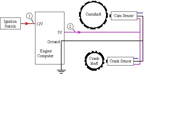
1. In the first drawing, the ignition switch is turned to the "run" position. 12 volts shows up at the Engine Computer to turn it on. (Cute little number "1" in the circle).

2. The computer generates a carefully-regulated 5.0 volt power supply to run multiple sensors, including the cam and crank sensors. That 5.0 volts feeds the two sensors on the purple wire. The ground return wire is common to all the sensors on the engine. It goes through the computer so it can be monitored. At this point, the sensors are waiting to start detecting movement of their sprockets or tone rings by looking at the notches cut into those sensor rings.

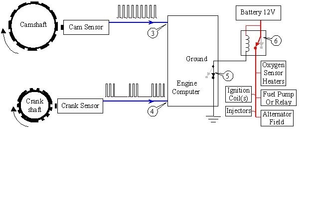
In the second nifty drawing, the sprockets are rotating, either from the starter cranking the engine, or because the engine is running. Each time a notch passes by the tip of the sensor, a pulse of voltage is generated. It is amplified by each sensor's internal circuitry to send out pulses that switch between 0.0 and 5.0 volts.

3. The camshaft sprocket is shown with 12 notches, but the actual number will vary between engines and years. I think yours only generates two pulses per revolution. When an engine uses an ignition coil pack with two, three, or four individual coils, the notches will have offset spaces and gaps so the computer can figure out which piston is coming up on top dead center. That's how it knows which coil to fire. When you have a distributor, it's up to the position of its rotor to send spark voltage to the correct spark plug. The computer only has to know when to fire the one ignition coil. It doesn't know which cylinder it's firing.

4. The crankshaft sprocket has three groups of notches with a different number of notches per group. With this arrangement, the computer knows which pair of pistons are coming up on top dead center. One will be on the compression stroke, and one will be on the exhaust stroke. Both spark plugs fire at the same time. Once the crankshaft rotates at least one full revolution, the computer will know which ignition coil to fire when it sees the oddball number of notches.

With this design, the signal pulses from the crankshaft position sensor just tell the computer which cylinders to fire next. It's the signal from the camshaft position sensor that tells it very precisely when to fire that spark plug. The opposite is true for some other engines. It can be the camshaft position sensor that tells the computer which coil to fire, and the crankshaft position sensor is the one that dictates the precise spark timing. Some engines use one signal for precise spark timing and the other one for precise injector timing. We don't need to know that. We only care that both signals are there.

5. When the computer sees both signals at "3" and "4", it turns on its internal switch to ground the coil inside the automatic shutdown, (ASD) relay.

6. Energizing the ASD relay turns on its high-current switch, ("6"), and that sends current, on the red wires, to all the circuits shown.

The fuel pump is grounded already, so it runs. The computer grounds the oxygen sensor heaters to make them operate. It grounds the injectors for a very short, pre-programed amount of time to allow them to spray fuel into the intake manifold, then that ground is turned off until the next squirt of fuel is needed. The ignition coils are just the opposite but work the same way. The computer keeps them grounded so a nice big electromagnetic field builds up inside them, then it turns that ground off the exact instant it wants that coil to fire a spark plug. The magnetic field built up relatively slowly when the ground was turned on, but when the ground is turned off, that really strong magnetic field has no choice but to collapse instantly. That really fast movement of that collapsing magnetic field is what induces the really high voltage in the primary part of the ignition coil, then that is seriously-multiplied in the secondary part where the spark voltage is developed. The computer turns the ignition coil's ground off at the precise time it wants a spark, then it turns that ground back on as soon as possible to give the magnetic field plenty of time to build up for the next event.

The purpose of this system is if the fuel line is ruptured in a crash, the electric fuel pump would keep on dumping raw gas onto the ground where it would be a major fire hazard. With a broken fuel line, there can't be any pressure in it. With no pressure, no fuel will spray from the injectors. That causes the engine to stall. Once the crankshaft and camshaft are no longer rotating, the two sensors stop generating signal pulses. The computer sees that as it's time to turn the ASD relay off. That kills the 12 volts going to the fuel pump.

The only difference on your car is the fuel pump is fed its 12 volts through its own fuel pump relay instead of through the ASD relay. Both relays get turned on and off at the same time, just by different circuits in the computer.

There's three ways the engine can have a crank / no-start problem. The least common is when the ignition coil fails, as it appeared was the case with your car. The symptom is no spark. The next way is the fuel pump fails. The symptoms are you'll have spark, but no fuel pressure. By far, the most common failure is when one of the sensors fails. The computer turns off the ASD relay, so that results in no spark AND no fuel pump, AND no injector pulses. Where many people become confused is the pump still runs for one second each time the ignition switch is turned on, and that is why there is fuel pressure in the line, when it is checked.
Was this
answer
helpful?
Yes
No
+1
Monday, January 29th, 2018 AT 7:25 PM
Tiny
PEGGIESEBRING
  • MEMBER
  • 17 POSTS
I'm gonna try a crankshaft position sensor I'm confused and I thought leaning I wasn't getting injector pulse would have helped
Was this
answer
helpful?
Yes
No
Wednesday, January 31st, 2018 AT 11:56 PM
Tiny
MITCH THOMPSON
  • MEMBER
  • 1 POST
CARADIODOC, holy cow those are some detailed explanations. I'm troubleshooting the exact same problem, exact same steps. I have fuel (lord I can smell it in the exhaust) so I know the cam / crank sensors are happy. There is no spark. Everything points to the distributor but I can't find single thing wrong with it. I checked the FET inside and it reads ok. The coil checks out ok 1.3 ohms per coil. I am at a loss why there's no spark. Guess I'll have to go over it all again!

Edit: manually tested the coil, it doesn't spark. I bought the incorrect replacement (Mitsubishi Colt, almost identical but the spark output is a little shorter). Tested the new coil using a 12v power supply and got a beautiful little 4mm spark and a nice jolt up my arm. Means the old one is definitely toast. Gonna reorder. $16 part!

Edit: I might add that the "bad" coil read ok on a multimeter but didn't actually work. Readings were identical to the new one!
Was this
answer
helpful?
Yes
No
Wednesday, April 28th, 2021 AT 7:11 PM
Tiny
CARADIODOC
  • MECHANIC
  • 33,754 POSTS
So you're saying it's work9ing now, or are you still waiting for parts?

As for testing parts like ignition coils and injectors, we never measure their resistance to do a diagnosis, only later if we wish to learn why that part wasn't working. The problem with measuring them is very often they'll measure out-of-specs, but still be working just fine, especially with injectors. Numbers given in the service manual are just for reference. When you take a properly-working part, then measure its resistance just for the fun of it, you'll find it reads out-of-specs just as often as one reads in-specs.

The other problem, mostly with ignition coils, is carbon-tracking can develop internally. That has such a high resistance that you'll still be reading mainly the coil of wire itself, but in service the voltage will find it easier to jump across that carbon tracking than to jump the spark plug's gap. This is where you might get a real weak spark from the coil. The only other way to get weak spark is for a good percentage of the loops of wire in the secondary coil to be shorted together. That is physically pretty hard to have happen. In that case you would find its resistance to be much too low, but that would be a very uncommon failure.

Please let me know when you have this solved.
Was this
answer
helpful?
Yes
No
Wednesday, April 28th, 2021 AT 9:33 PM

Please login or register to post a reply.

Sponsored links