Ken posted aftermarket diagrams, but sometimes they can be hard to read. These are original Chrysler diagrams. As a former tv / vcr repairman, these are very different types of diagrams, but once you get used to them, they can be rather easy to follow. First let me share what I typed up earlier:
You need to list the engine size so I can post the right diagrams. The coupe has a 3.0L V-6 Mitsubishi engine available, and the sedan has a 2.7L Chrysler engine available.
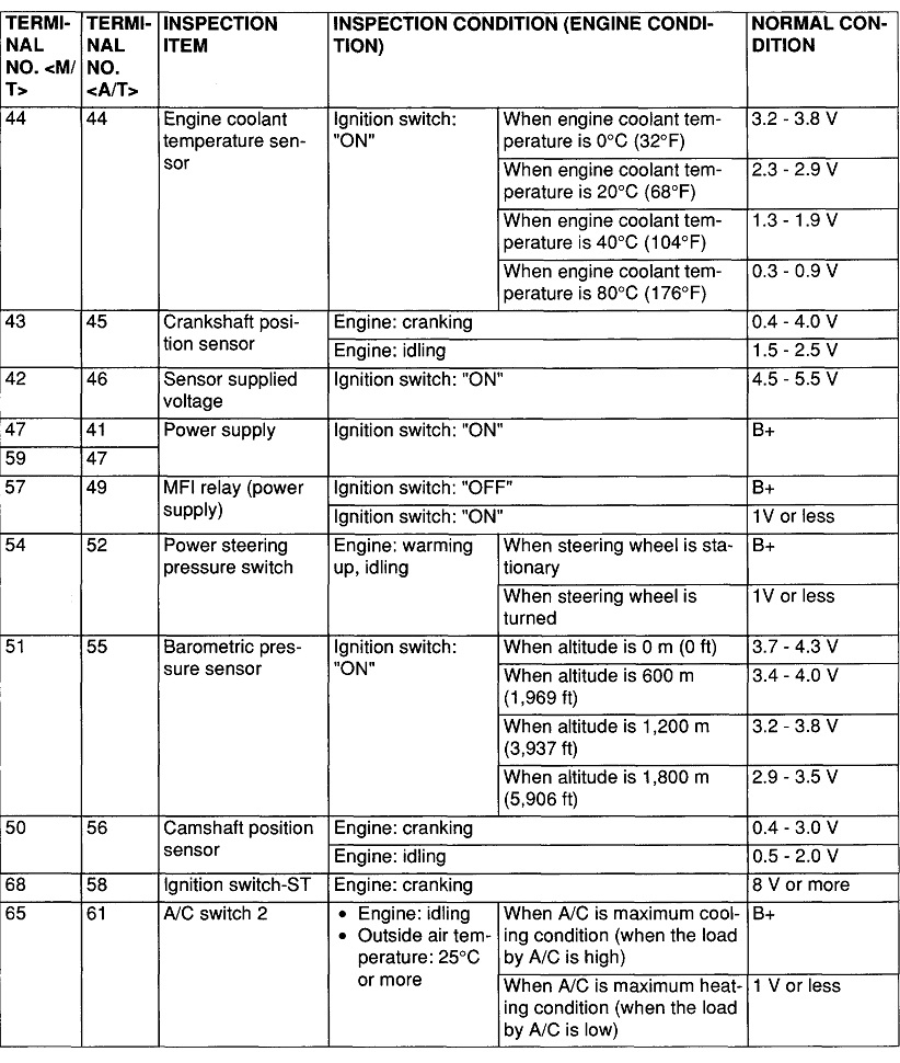
The first step is always to read and record any diagnostic fault codes. Chrysler made doing that yourself much easier than any other manufacturer. Cycle the ignition switch from "off" to "run" three times within five seconds without cranking the engine. Leave it in "run", then watch the code numbers appear in the odometer display. You can go here:
https://www.2carpros.com/trouble_codes/obd2/p0700
to see the definitions, or I can interpret them for you.
Next is to check for spark. This article shows how to do that:
https://www.2carpros.com/articles/how-to-check-for-ignition-spark
The loss of fuel pump you're trying to diagnose only accounts for about three percent of crank / no-starts. Loss of just spark only accounts for about another two percent. By far the most common cause of crank / no-starts is a loss of fuel pump, spark, and injector pulses, roughly 95 percent. That's why we have to look for any other systems that are also dead, not just the fuel pump.
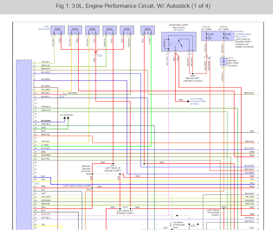
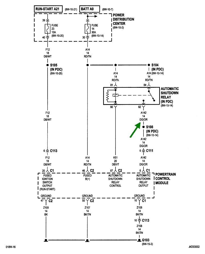
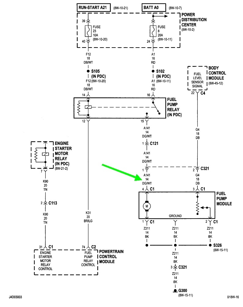
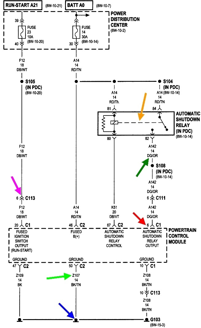
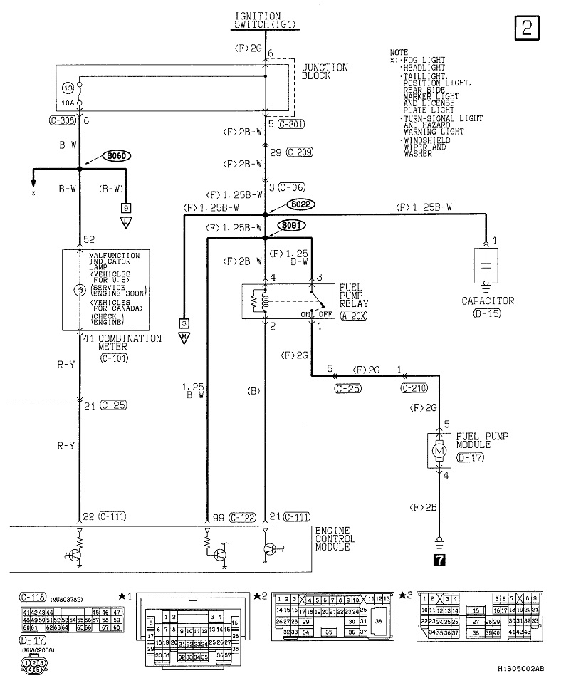
This first diagram is for the 2.7L automatic shutdown, (ASD) relay. It gets turned on by the Engine Computer at the same time as the fuel pump relay gets turned on. That entire pump circuit is shown in the second diagram. You should find 12 volts on the dark green / white wire for one second when the ignition switch is turned on, then it will go back to 0 volts. If you find that, the entire circuit up to that point is okay. You should also hear the hum of the fuel pump during that one second. If you do, the pump is working.
What's important is if that 12 volts comes back when a helper cranks the engine. If it does not, chances are you won't have spark either. That circuit comes through the ASD relay. The fastest way to check that is to find the wire that is the same color at any injector, any ignition coil, or either smaller terminal on the back of the alternator. A test light works better for this because most digital voltmeters don't respond fast enough. If you need it, here's an article that shows how to use a test light:
https://www.2carpros.com/articles/how-to-use-a-test-light-circuit-tester
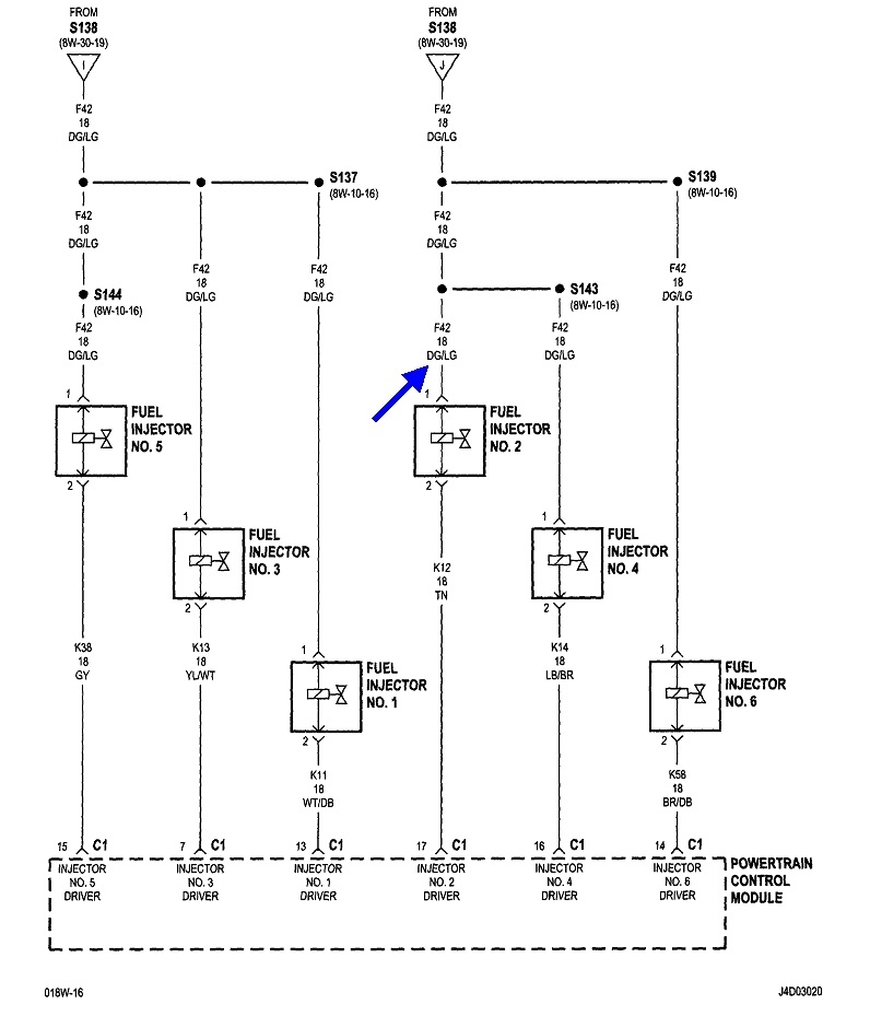
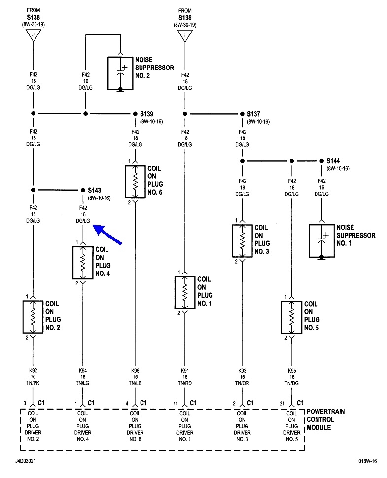
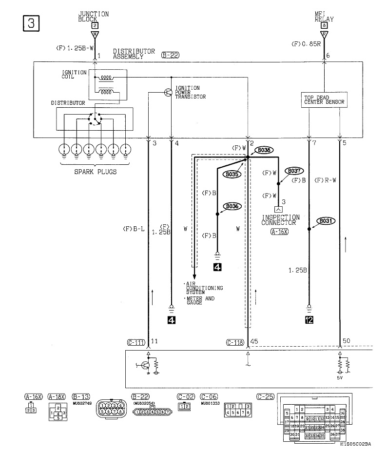
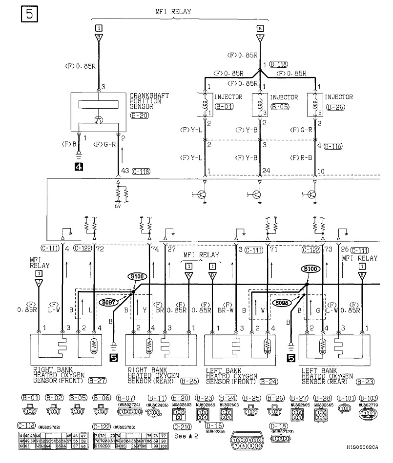
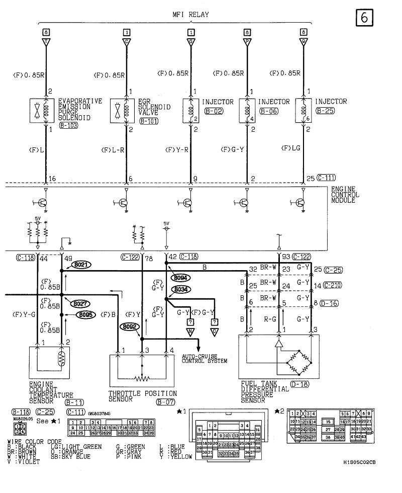
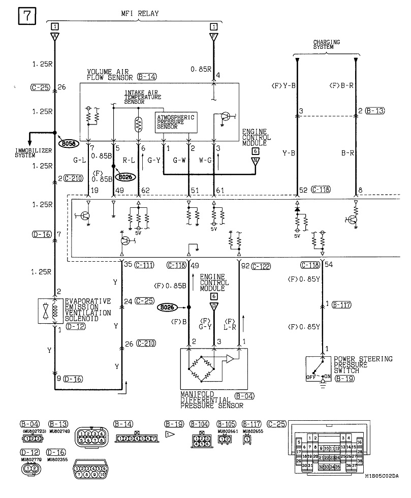
On this model the wire to check on is dark green / light green wire. The fourth diagram shows all the injectors being fed on that dark green / light green wire. The fifth diagram shows the same thing for the ignition coils.
Let me know what you find up to this point.
Okay, to continue, when it comes to reading diagrams, I add arrows that I can make reference to, but I assume most people can't follow the diagrams, but they can find the connectors on the vehicle if I describe them. I expand these as much as possible for easier viewing, but if you still have trouble, there's two solutions. One is I can cut them in half, then expand them even more and post the parts separately. The easier solution is for you to right-click a diagram, click "copy image", then use a typing program such as MS Word and paste it there. From there you can expand it, enlarge it, and add notes to it. I can help with all of that too.
To address the first order of confusion, when you see a wire designation, such as by the dark green arrow in the first diagram, it's "A142 14 DG / OR". "A" circuits are those that originate right at the battery's positive terminal, or they have full battery voltage switched onto them at some point. "Z" circuits are grounds. If you do this long enough, you'll see that other circuits use their own same letters over many years and models. The "142" is the circuit number. All we care about here is if you run into that same number somewhere else, it's the same circuit. The "14" means it's a 14 gauge wire. Often you'll find as you go further through the circuit, the gauge number gets higher, (meaning a smaller diameter wire), but the circuit number stays the same. It's still the same circuit. The "DG / OR" means it's a dark green wire with an orange stripe, or "tracer".
Just below the dark green arrow is a black dot labeled "S108 (in PDC)". That's splice 108 and it's inside the Power Distribution Center. That's the name for the under-hood fuse box. They name them to make telling them apart easier. There's always another fuse box inside the vehicle. That's called the "Junction Box".
Here's where the differences from tv diagrams really becomes apparent. With tvs, every part of every circuit is shown on huge fold-out pages. With cars, they only show you the parts that are relevant to the circuit. "S108" makes this point. When the ASD relay is switched on, the 12 volts runs to a lot of places, but here they're only showing that it goes to the "PCM", (power train control module). I call them the "Engine Computer" so I don't have to confuse myself with the terms used on other brands. Use the sixth diagram for this explanation. It's the first one, but I cropped it, expanded it, and added a pile of arrows. The PCM turns on the ASD relay, then, that 12 volts goes to many places, including, in this diagram, right back to the PCM on a different terminal as a verification to say, "yes, that relay did turn on, and here's proof". Once the computer sees that 12 volts, it starts doing all the other things it has to do.
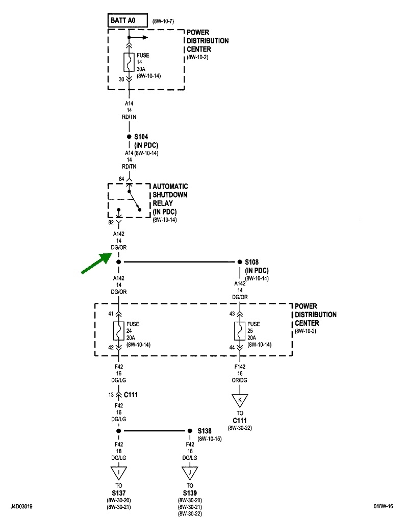
What this diagram doesn't show is what else takes off from splice 108. I've had to look through as many as 30 diagrams to find more parts of circuit 142, but with experience, you learn what to look for and it isn't a big deal. In this case, that's why I posted the fourth and fifth diagrams, but I have to correct something here. On all other Chrysler models, circuit 142 goes directly to the injectors and ignition coils. On the Stratus, they added fuses to each of those circuits. Those are shown in the third diagram. Because they both continue on as fused circuits, their designations have changed from "A" to "F". Backing up a bit, splice S108 is shown as before, but this time they're only showing the two fuses that get the 12 volts. It's just understood there are other parts, or circuits, that also come off this splice.
We try to post fuse box layout drawings to show where the fuses are that need to be checked, when appropriate, but sometimes they can be hard to find in the online service manuals. Just be aware that is something we can include. If you follow down through fuse 24, they show in bold, "C111" next to a pair of small arrows pointing up. Those arrows indicate there's an inline connector, (connector 111), to allow separate sections to go together on the assembly line. (Those make dandy test points). The arrows indicate a pair of mating terminals within that connector. The "13" just left of the double arrow means that is terminal 13 in that connector. Chrysler is also real good about providing connector views. We post those too when appropriate. Those are most helpful when there's from 20 to 60 terminals in one connector. When there's a dozen or less, such as at your fuel pump, it's much easier and faster to just look for the certain wire color. Connector views are also helpful when you have a handful of wires that got torn out of the connector and you're trying to figure out where each one goes.
By the way, the wire color has changed now to dark green with a light green tracer.
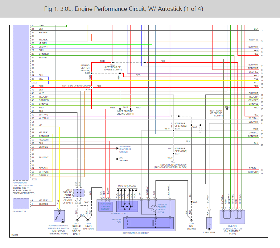
Continuing past C111, there's another splice, S138, I assume to run to each side of the engine. Something new that Chrysler started about 25 years ago is the triangles at the very bottom of this diagram. Note the letters inside them. There's too much diagram for one page, so they continued it on another page, usually the very next diagram, and you look for the same triangle at the top of that next page with the same letter inside it. Those triangles don't mean anything on the vehicle. No connectors, no splices, etc. It's just a continuation on the next page. Triangle "I" says it goes to splice S137, then under that it shows, "(8W-30-20). You don't have to worry about that unless you're using a paper copy of the service manual. The "8" refers to section 8 of the manual which is the electrical section. The "W" is the wiring section within section 8. Each system, such as wipers, cruise control, or interior lights has its own subsection. That's the "30", then within that subsection, they're sending you to "sheet 20" to see how that circuit continues on.
Those sheet numbers are another confusing point at first. When the engineers put all these diagrams together, they try to put them in a logical order, but there's no way to know which page numbers they'll end up being in the book. It would take forever to change each of the thousands of sheet numbers to page numbers, and even if they did, that would be different for other models with various groups of options. By using sheet numbers, there is a real lot of standardization between models and years. You don't have to concern yourself with those designations because we will post all the relevant diagrams for the problem you're working on. Those sheet numbers also do not apply when using online manuals. They're only there because this is an original diagram that was scanned out of the manufacturer's paper manual. These aren't included on aftermarket diagrams either.
Moving on to the fourth and fifth diagrams, each one has a triangle "I" and "J" at the top, so that's where the circuits continue on. Standard practice is to always start at the top and end at the bottom, although once in a while that doesn't work out. Just follow the lines to follow the circuit. Both circuits are tied together, so they have the same "F42" designation. Only the splice is between the two lines. One line runs along each side of the engine and feeds three injectors and three ignition coils. These are the places I originally told you to look with a test light to see if the ASD relay is turning on. Nothing can work if that 12 volts doesn't show up.
Once you go through each coil or injector, you'll see each one has its own ground, or "return wire going to the Engine Computer. That makes 12 individual switching circuits the computer uses to turn each coil or injector on and off at the right times. The wires will usually be the same color, but with different tracers to tell them apart, as shown with the injectors. One is tan / pink, one is tan / light green, etc. You may also see these referred to as "control" wires or circuits, or "switched" circuits.
While I'm at it, I might as well explain why this system seems so unnecessarily complicated. It all starts with the crankshaft position sensor and the camshaft position sensor. When you turn on the ignition switch, the Engine Computer turns on the ASD relay for one second. In that time it verifies that circuit is working, then, it turns that relay back on when it sees engine rotation, (cranking or running). It knows that by the signal pulses it receives from those two sensors. When you check at any injector or ignition coil with the test light, if the 12 volts is not there during cranking, it's one of those two sensors that is responsible most of the time.
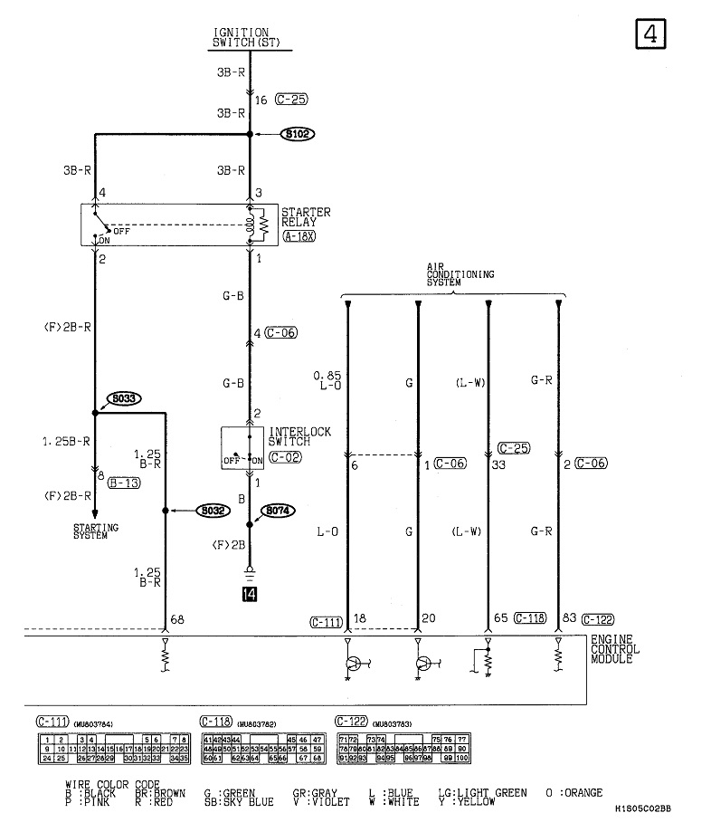
When both signals show up and the computer turns the ASD relay back on, it's those signal pulses that are the timing pulses to tell the computer exactly when to fire an injector or coil. That's a whole different part of the story. When we're looking at a failure to run, we just care if the ASD relay is turning on or it isn't. The purpose of this system is if the vehicle is involved in a crash that ruptures a fuel line, the fuel pump will keep right on running and dump raw gas on the ground until the battery runs dead. Obviously, that can't be allowed to happen. With a torn fuel line, there can't be any fuel pressure. With no pressure, fuel can't spray from the injectors, so the engine stalls. With a stalled engine, there won't be any signal pulses from the crank or cam sensors. When the computer sees the lack of pulses, it turns the ASD relay off. On other models that removes the 12 volts from the ignition coils, injectors, other places, and the fuel pump, so the pump stops pouring gas on the ground. On your model, and a few others, they split the job up between the automatic shutdown relay and a separate fuel pump relay. They switch on and off at the same time, but their circuits are independent of each other.
For any electrical circuit to work, it has to be a "complete" circuit, meaning current flow starts at the battery, flows through connectors, switches, and the "load", and ends back at the battery. There's two ways of looking at that, but in automotive and tv work, we customarily start at the positive battery terminal, (at the top of the page), flow through the circuitry, then end up at the battery's negative terminal. There can be hundreds of circuits and sub circuits, so rather than run hundreds of wires back to the battery, we use the body sheet metal and frame as a common tie point, then run just two wires back to the negative post. One comes from the body and a real large one comes from the engine. They need separate cables because the engine is mounted on rubber mounts that would insulate it. As I mentioned, "Z" circuits, such as by the light green arrow, are ground wires. At the very bottom is the symbol Chrysler uses to indicate that wire is grounded to, or bolted to the body. No other tv or auto manufacturer in the world uses that symbol of a giant dot over a line. At a Chrysler training class, it was explained they did that because it was the only symbol at the time they could make with a typewriter. Everyone got used to it, so they just kept on using it.
With that, Ken will be back to help you. I'll pop back if you have more questions on reading diagrams.
Images (Click to enlarge)
Aug 12, 2022 at 5:37 PM