What is your battery voltage at before you try cranking (so static battery voltage) and then what does the battery voltage drop to when trying to crank it over? It's possible there is a connector issue (corroded connector or pin fitment issue). When you say you have voltage on the High-speed bus, High and Low what voltage readings are you getting? The bus should have a bias voltage of 2.5volts in between message packets, if you're using a multimeter, it will only be able to average the voltage level out that is reading because the bus speed is too fast for a multimeter. The canbus High goes from 2.5v to 3.5v and canbus Low goes from 2.5v to 1.5v. I'll post a waveform of a canbus signal, but I would check your battery voltage levels first. Make sure the battery is not dropping off when it's under a load like trying to start. Are you getting any codes stored in any modules at all?
And were you moving any sections of the harness around while doing any voltages checks? If you were, take note of the section or of any connectors you may have moved. Corroded connectors or loose pins will cause these types of issues, some wires are making a connection, and some are not.
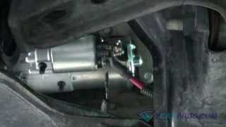
The starter pulls a huge amount of amperage, so it's possible it is pulling the battery right down to where its flat lining the battery is.
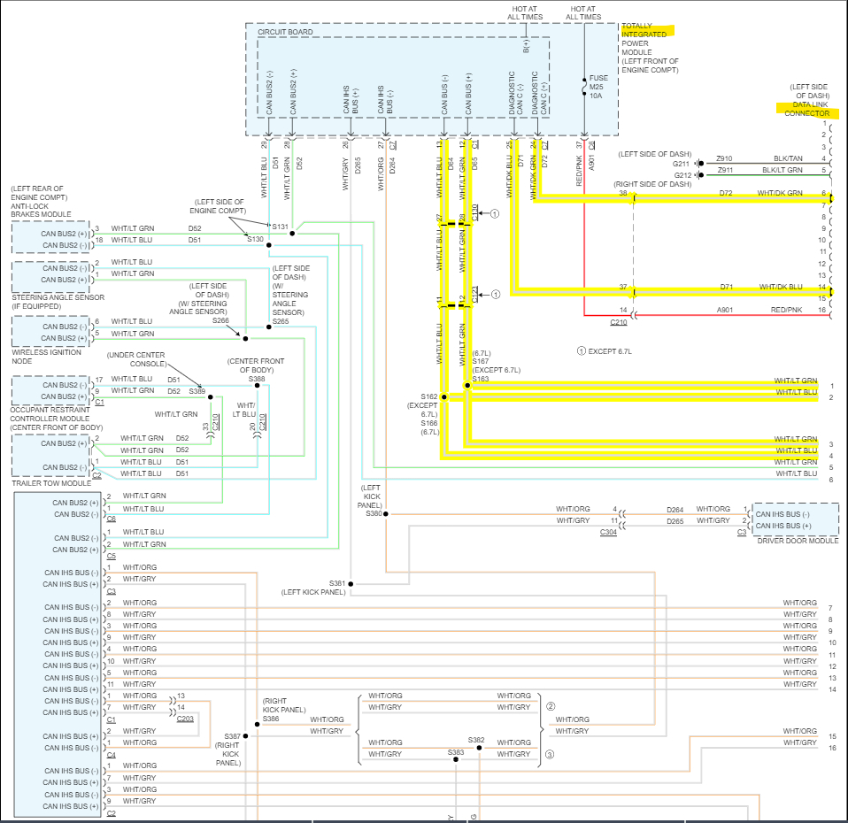
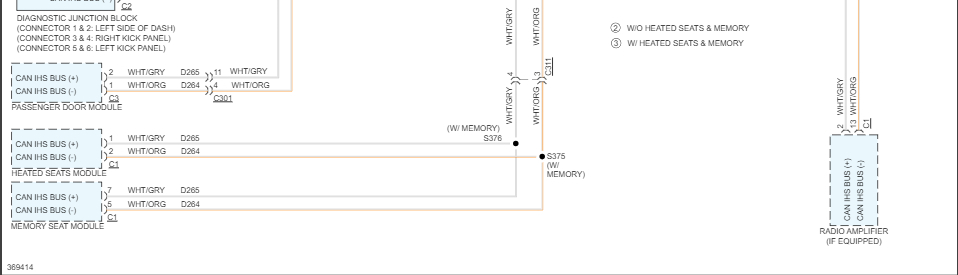
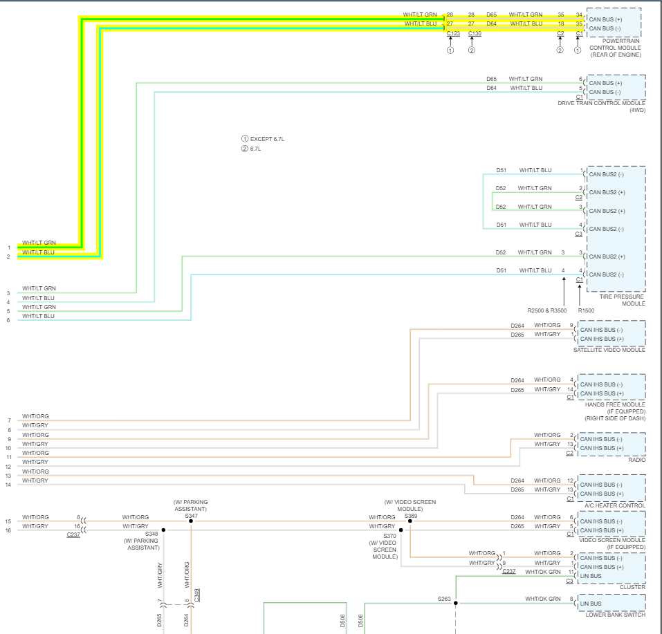
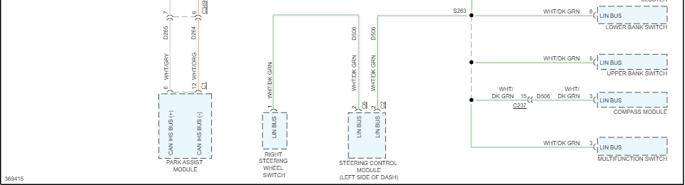
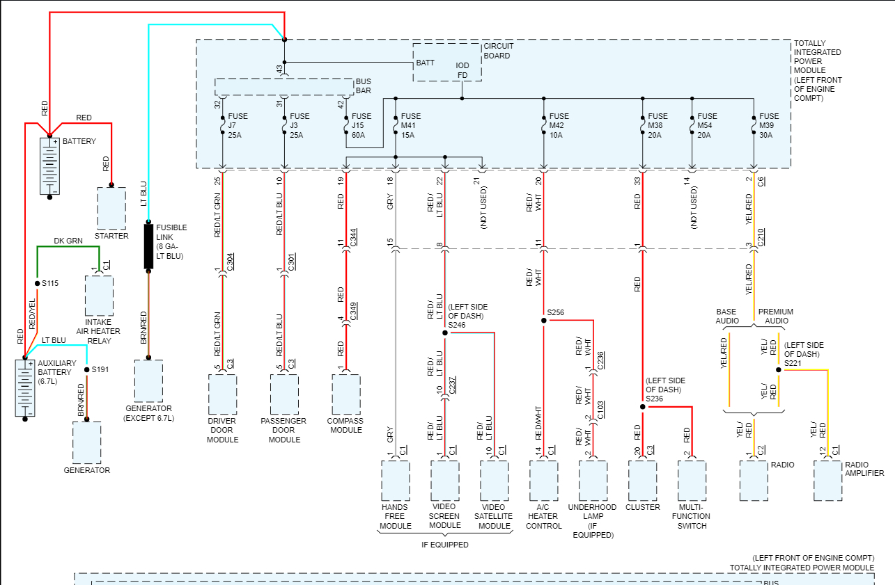
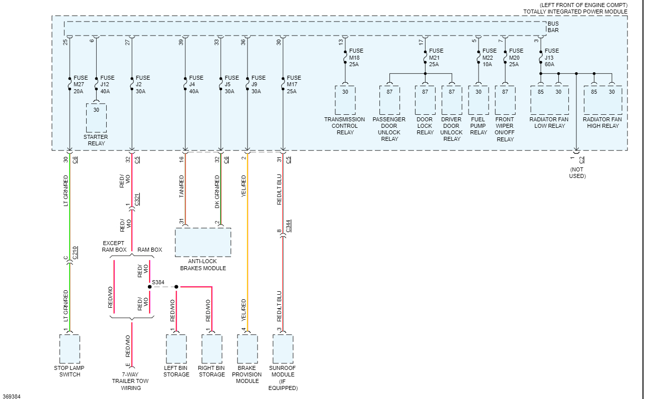
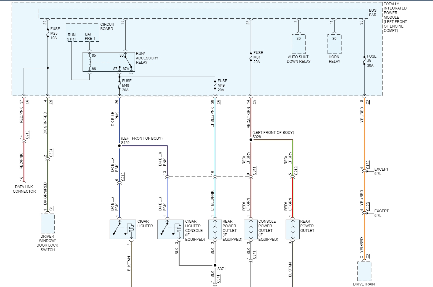
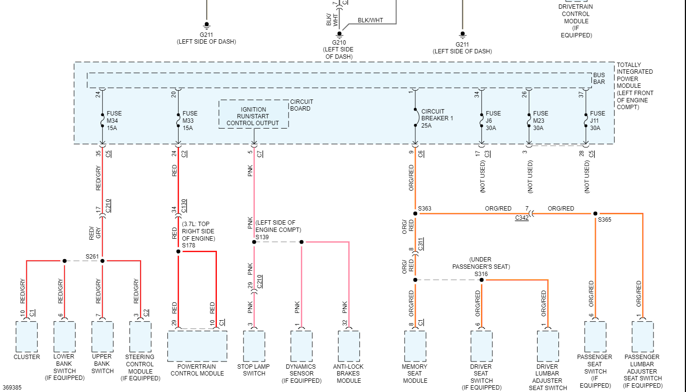
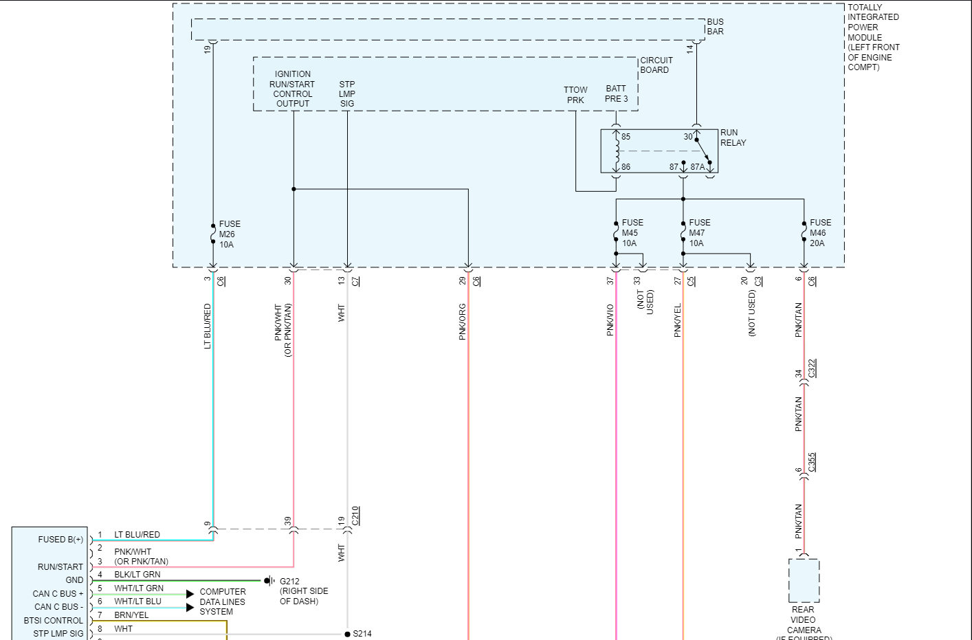
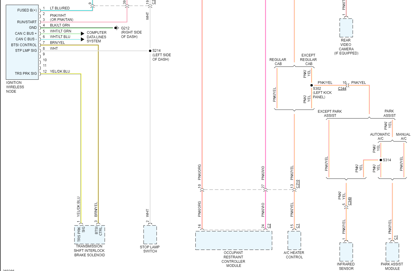
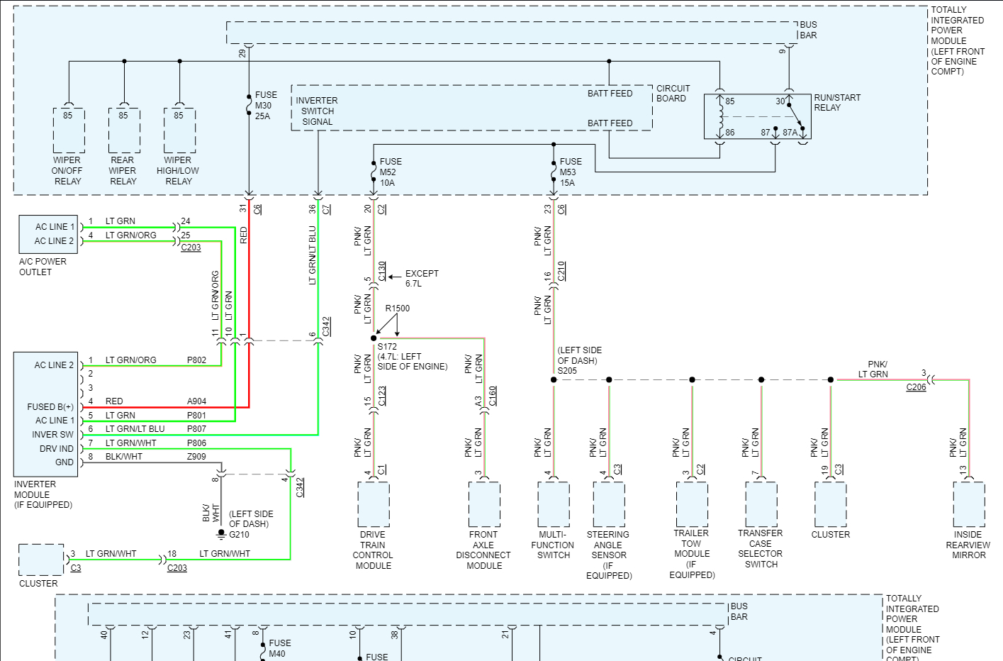
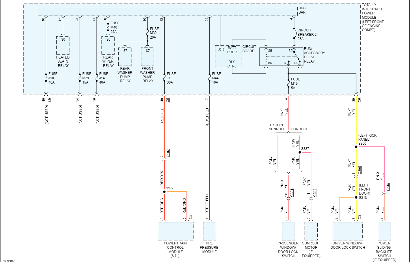
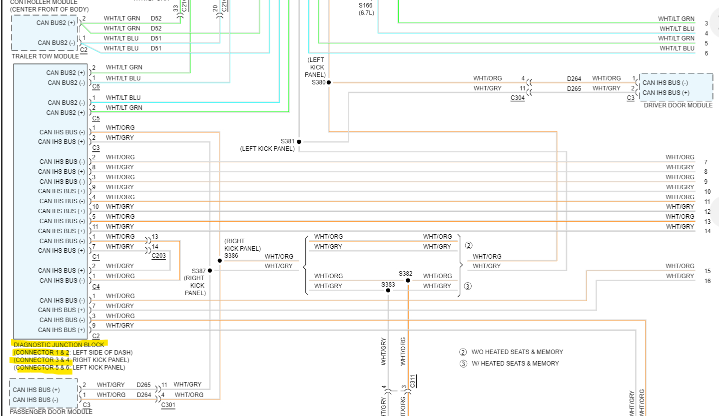
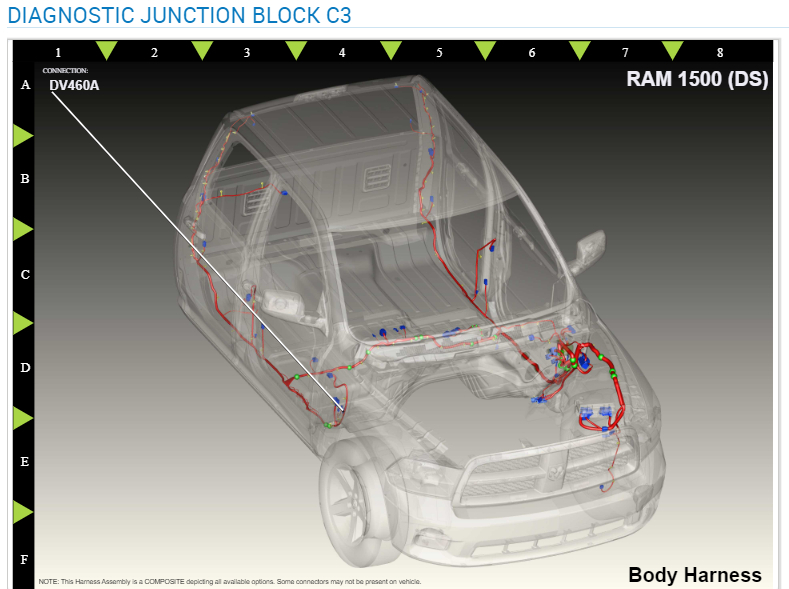
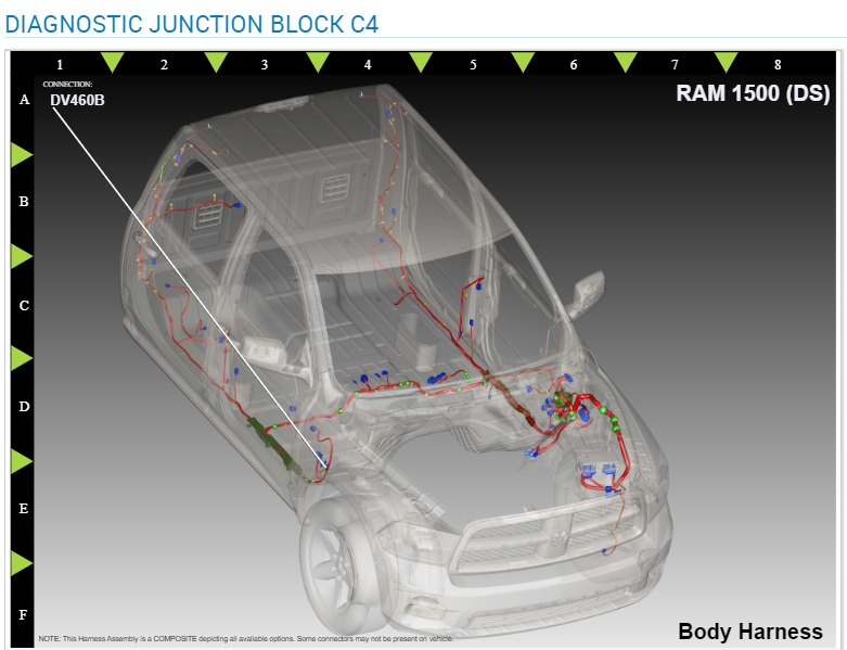
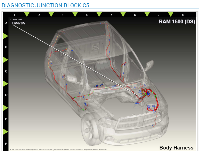
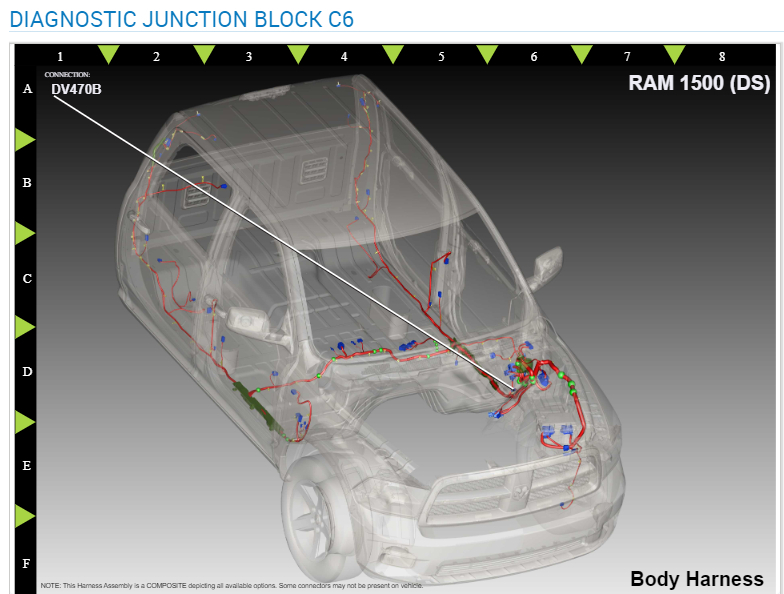
You can also check the connectors under the TIPM for any corrosion or connector issues. The TIPM has an internal circuit board and uses the data bus as well and acts as a Body control module as it looks like on this vehicle. Check out this Diagnostic Junction Block, it looks like there are multiple connectors for it under both driver side and passenger side kick panels and driver side dash.
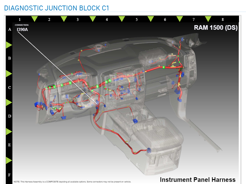
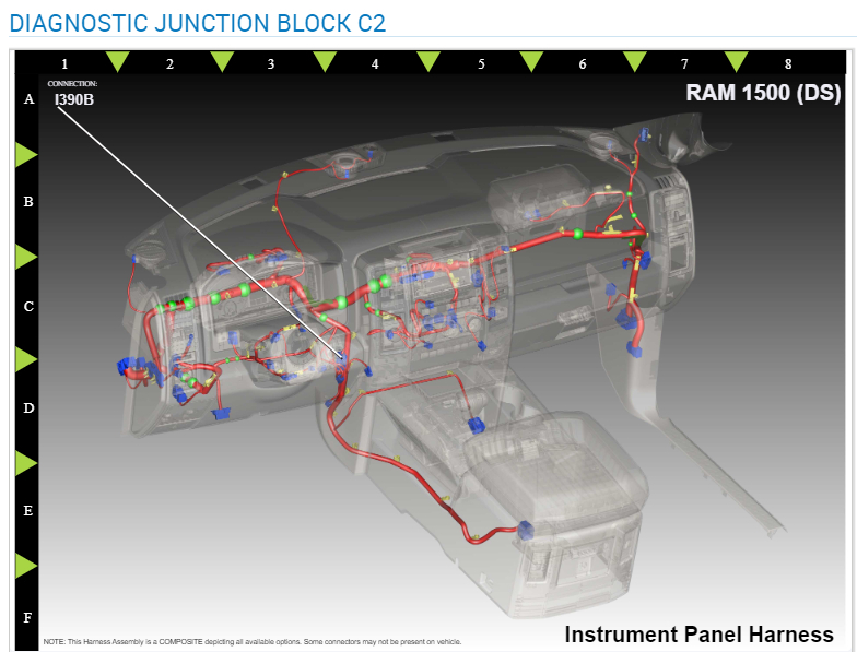
These are the locations of those Diagnostic Junction Block connectors, but a NoBus message could happen with low voltage as well, a module can't communicate if it's not powered up fully. And now you have scan tool comms back, it sounds like you may have moved the harness around somewhere that has a connector issue. So, retrace your steps so far.
Images (Click to make bigger)
Friday, September 22nd, 2023 AT 7:54 AM