Welcome back:
As far as the PCM, for a dealership, that is about normal. Honestly, I don't have any contacts for ones that are already programmed. Would they allow you to purchase one and have them program it?
Honestly, I have all the directions for programming and removal and replacement, but it is an extensive process when the PCM is new, and it requires a specific type of scan tool. Regardless, I will provide you with the directions for removal and replacement and what has to be done to program the new one. The attached pictures correlate with these directions.
____________________________________________
POWERTRAIN CONTROL MODULE - REMOVAL
REMOVAL
CAUTION: Certain ABS systems rely on having the Powertrain Control Module (PCM) broadcast the Vehicle Identification Number (VIN) over the bus network. To prevent problems of DTCs and other items related to the VIN broadcast, it is recommend that you disconnect the ABS CAB (controller) temporarily when replacing the PCM. Once the PCM is replaced, write the VIN to the PCM using a scan tool. This is done from the engine main menu. Arrow over to the second page to "1. Miscellaneous". Select "Check VIN" from the choices. Make sure it has the correct VIN entered before continuing. When the VIN is complete, turn off the ignition key and reconnect the ABS module connector. This will prevent the setting of DTCs and other items associated with the lack of a VIN detected when you turn the key ON after replacing the PCM.
CAUTION: Use the scan tool to reprogram the new PCM with the vehicles original identification number (VIN) and the vehicles original mileage. If this step is not done, a Diagnostic Trouble Code (DTC) may be set.
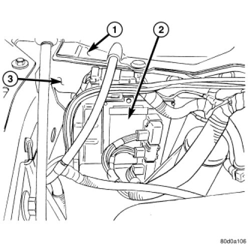
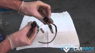
Pic 1
The PCM (1) is located in the engine compartment attached to the dash panel (3).
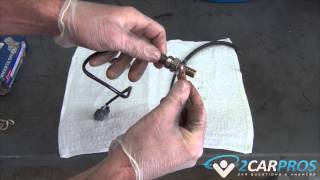
Pic 2
To avoid possible voltage spike damage to the PCM, ignition key must be off, and negative battery cable must be disconnected before unplugging PCM connectors.
1. Disconnect negative battery cable at battery.
2. Remove cover over electrical connectors. Cover snaps onto PCM.
3. Carefully unplug the three 32-way connectors (four 38-way connectors if equipped with NGC) from PCM (1).
4. Remove three PCM mounting bolts (4) and remove PCM from vehicle.
____________
POWERTRAIN CONTROL MODULE - INSTALLATION
INSTALLATION
CAUTION: Certain ABS systems rely on having the Powertrain Control Module (PCM) broadcast the Vehicle Identification Number (VIN) over the bus network. To prevent problems of DTCs and other items related to the VIN broadcast, it is recommend that you disconnect the ABS CAB (controller) temporarily when replacing the PCM. Once the PCM is replaced, write the VIN to the PCM using a scan tool. This is done from the engine main menu. Arrow over to the second page to "1. Miscellaneous". Select "Check VIN" from the choices. Make sure it has the correct VIN entered before continuing. When the VIN is complete, turn off the ignition key and reconnect the ABS module connector. This will prevent the setting of DTCs and other items associated with the lack of a VIN detected when you turn the key ON after replacing the PCM.
CAUTION: Use the scan tool to reprogram the new PCM with the vehicles original identification number (VIN) and the vehicles original mileage. If this step is not done, a Diagnostic Trouble Code (DTC) may be set.
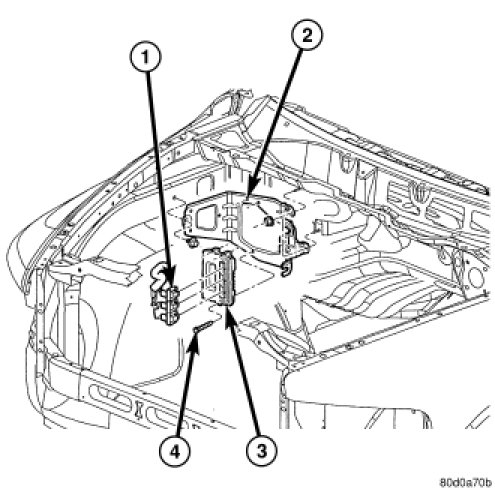
Pic 3
1. Install PCM (3) and 3 mounting bolts (4) to vehicle.
2. Tighten bolts. Refer to torque specifications.
3. Check pin connectors in the PCM and the three 32-way connectors (four 38-way connectors if equipped with NGC) for corrosion or damage. Also, the pin heights in connectors should all be same. Repair as necessary before installing connectors.
4. Install three 32-way connectors (four 38-way connectors if equipped with NGC).
5. Install cover over electrical connectors. Cover snaps onto PCM.
6. Install negative battery cable.
7. The 5.7L V-8 engine is equipped with a fully electronic accelerator pedal position sensor. If equipped with a 5.7L, also perform the following 3 steps:
a. Connect negative battery cable to battery.
B. Turn ignition switch ON, but do not crank engine.
C. Leave ignition switch ON for a minimum of 10 seconds. This will allow PCM to learn electrical parameters.
D. The scan tool may also be used to learn electrical parameters. Go to the Miscellaneous menu, and then select ETC Learn.
8. If the previous step is not performed, a Diagnostic Trouble Code (DTC) will be set.
9. If necessary, use a scan tool to erase any Diagnostic Trouble Codes (DTC's) from PCM. Also use the scan tool to reprogram new PCM with vehicles original Vehicle Identification Number (VIN) and original vehicle mileage.
_____________________________
Programming a new PCM
Replacement PCM's will require programming utilizing the StarSCAN(R) or equivalent. The PCM will not operate the engine until it is programmed. A Diagnostic Trouble Code (DTC) will be set - "not programmed".
CAUTION: Extreme care must be taken when programming a calibration into a generic PCM. Do not randomly select a calibration. Once a calibration is selected and programmed, the controller cannot be reprogrammed to a different calibration. The module can only be reprogrammed to a more recent version of that calibration.
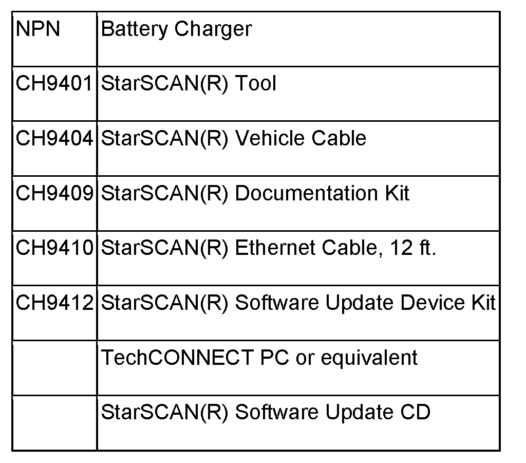
SPECIAL TOOLS/EQUIPMENT OR EQUIVALENT REQUIRED:
pic 4
**REPAIR PROCEDURE - USING THE INTERNET TO RETRIEVE THE FLASH FILE:
NOTE: The StarSCAN(R) or equivalent diagnostic scan tool fully supports Internet connectivity. However, in order to take advantage of this feature you must first configure the StarSCAN(R) or equivalent for your dealership's network.
NOTE: If this flash process is interrupted/aborted, the flash should be restarted.
1. Open the hood, install a battery charger and verify that the charging rate provides approximately 13.5 volts. Set the battery charger timer to maintain the charging voltage for the duration of the flash process.
2. Connect the CH9410 StarSCAN(R) or equivalent ethernet cable to the StarSCAN(R) or equivalent and the dealer's network drop.
3. Connect the CH9404 StarSCAN(R) or equivalent vehicle cable to the StarSCAN(R) or equivalent and the vehicle.
4. Power ON the StarSCAN(R) or equivalent.
5. Retrieve the old ECU part number. Using the StarSCAN(R) or equivalent at the "Home" screen:
a. Select "ECU View"
b. Touch the screen to highlight the PCM in the list of modules.
C. Select "More Options"
d. Select "ECU Flash"
e. Record the part number at the top of the "Flash PCM" screen for later reference.
6. Replace the PCM with the appropriate Generic PCM.
7. Program the PCM as follows:
a. Using the StarSCAN(R) or equivalent at the "Home" screen, Select "ECU View"
b. Touch the screen to highlight the PCM in the list of modules.
C. Select "More Options"
d. Select "ECU Flash"
e. Select "Browse for New File". Follow the on screen instructions.
F. Highlight the appropriate calibration based on the part number recorded in Step 5.
G. Select "Download to Scantool".
H. Select "Close" after the download is complete, then select "Back".
I. Highlight the listed calibration.
J. Select "Update Controller". Follow on screen instructions.
K. When the update is complete, select "OK".
L. Verify the part number at the top of the "Flash PCM" screen has updated to the new part number.
8. Is "WCM - Wireless Control Module" displayed in the "ECU Overview" screen list of modules?
A. Yes >> go to STEP 9.
B. No >> go to STEP 10.
9. Program the PCM to the Wireless Control Module (WCM).
A. Highlight the WCM.
B. Select "Misc. Function".
C. Highlight "PCM Replaced".
D. Select "Start"
e. Follow the on screen instructions. Select "Next" after each step. Select "Finish" after completing the last step.
F. When complete proceed to STEP 11.
10. Program the VIN into the PCM.
A. Scroll through the list of controllers and highlight the PCM.
B. Select "Misc. Function".
C. Highlight "Check PCM VIN".
D. Select "Start".
E. Follow the on screen instructions. Select "Next" after each step. When the window appears with 17 boxes, select "Show Keyboard". Place the cursor to the right of the last box and then backspace to delete the boxes from the window. Enter the VIN. Select "Finish" after completing the last step.
F. Unplug the scan tool from the Data Link Connector.
G. At the "Vehicle Disconnected" screen, press "OK".
H. Connect the scan tool to the Data Link Connector and verify that the VIN is visible at the top of the "Home" screen.
11. Is the vehicle equipped with a 3.7L or 4.7L engine?
A. Yes >> go to STEP 13.
B. No >> go to STEP 12.
12. Using the StarSCAN(R) or equivalent at the "Home" screen:
a. Select ECU View
b. Scroll through the list of controllers and highlight the PCM.
C. Select Misc. Function.
D. Highlight "Learn ETC".
E. Select "Start"
f. Follow the on screen instructions. Select Next after each step. Select Finish after completing the last step.
NOTE: Due to the PCM programming procedure, a DTC may be set in other modules (TCM, BCM, MIC, SKREEM, etc.) Within the vehicle, if so equipped. Some DTC's may cause the MIL to illuminate. From the Home screen select System View. Then select All DTCs. Press Clear All Stored DTCs if there are any DTCs shown on the list.
NOTE: The following step is required by law when reprogramming a PCM and/or TCM.
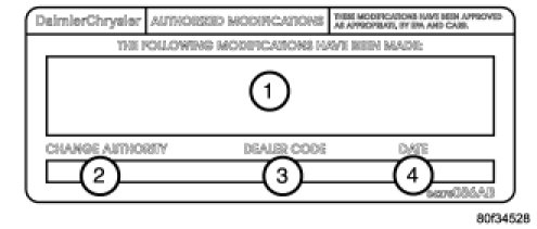
13. Type the necessary information on the "Authorized Modification Label" p/n 04275086AB and attach near the VECI label.
Pic 5
REPAIR PROCEDURE USING SOFTWARE UPDATE CD TO RETRIEVE THE FLASH FILE:
NOTE: If this flash process is interrupted/aborted, the flash should be restarted.
1. Open the hood, install a battery charger and verify that the charging rate provides approximately 13.5 volts. Set the battery charger timer to maintain the charging voltage for the duration of the flash process.
2. Connect the CH9404 StarSCAN(R) or equivalent vehicle cable to the StarSCAN(R) or equivalent and the vehicle.
3. Power ON the StarSCAN(R) or equivalent.
4. Retrieve the old ECU part number. Using the StarSCAN(R) or equivalent at the "Home" screen:
a. Select "ECU View"
b. Touch the screen to highlight the PCM in the list of modules.
C. Select "More Options"
d. Select "ECU Flash"
e. Record the part number at the top of the "Flash PCM" screen for later reference.
5. Replace the PCM with the appropriate Generic PCM.
6. Insert the StarSCAN(R) or equivalent Software Update CD into the Techconnect or equivalent PC. The StarSCAN(R) or equivalent Software Update CD will start automatically. Select "Download Flash Updates".
7. At the "Select a method for looking up controller flash updates." Screen:
a. Select "Enter part number". Enter the "Part Number" recorded in STEP 4 when prompted to do so.
B. Using the mouse highlight the appropriate "Calibration". Select "Next".
C. Follow the on screen instructions.
D. When completed, proceed to STEP 8.
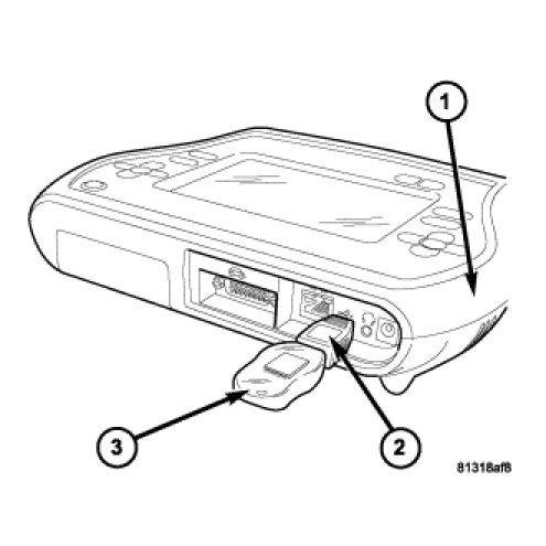
8. With the StarSCAN(R) or equivalent powered OFF, connect the USB Key and Gender Changer to the StarSCAN(R) or equivalent USB port.
Pic 6
9. Connect the StarSCAN(R) or equivalent to the vehicle (if not already connected).
10. Power ON the StarSCAN(R) or equivalent.
11. Download the flash file from the USB key to the StarSCAN(R) or equivalent. Using the StarSCAN(R) or equivalent at the "Home" screen:
a. Select "Flash Download", then select "Retrieve files from the USB storage device"
b. Highlight the appropriate calibration. Select "Download to Scan Tool"
c. When the download is complete, select "Close" and "Back".
12. Reprogram the ECU. Using the StarSCAN(R) or equivalent at the "Home" screen:
a. Select "ECU View".
B. Select More Options".
C. Select "ECU Flash".
D. Highlight the appropriate calibration.
E. Select "Update Controller". Follow the on screen instructions.
F. When the update is complete, select "OK".
G. Verify the part number at the top of the "Flash PCM" screen has updated to the new part number.
13. Is "WCM - Wireless Control Module" displayed in the "ECU Overview" screen list of modules?
A. Yes >> go to STEP 14.
B. No >> go to STEP 15.
14. Program the PCM to the Wireless Control Module (WCM). Using the StarSCAN(R) or equivalent at the "Home" screen:
a. Select "ECU View"
b. Scroll through the list of controllers and highlight the WCM.
C. Select "Misc. Function".
D. Highlight "PCM Replaced".
E. Select "Start".
F. Follow the on screen instructions. Select "Next" after each step. Select "Finish" after completing the last step.
G. When complete proceed to STEP 16.
15. Program the VIN into the PCM.
A. Scroll through the list of controllers and highlight the PCM.
B. Select "Misc. Function".
C. Highlight "Check PCM VIN".
D. Select "Start".
E. Follow the on screen instructions. Select "Next" after each step. When the window appears with 17 boxes, select "Show Keyboard". Place the cursor to the right of the last box and then backspace to delete the boxes from the window. Enter the VIN. Select "Finish" after completing the last step.
F. Unplug the scan tool from the Data Link Connector.
G. At the "Vehicle Disconnected" screen, press "OK".
H. Connect the scan tool to the Data Link Connector and verify that the VIN is visible at the top of the "Home" screen.
16. Is the vehicle equipped with a 3.7L or 4.7L engine?
A. Yes >> go to STEP 18.
B. No >> go to STEP 17.
17. Using the StarSCAN(R) or equivalent at the "Home" screen:
a. Select "ECU View"
b. Scroll through the list of controllers and highlight the PCM.
C. Select "Misc. Function".
D. Highlight "Learn ETC".
E. Select "Start"
f. Follow the on screen instructions. Select "Next" after each step. Select "Finish" after completing the last step.
NOTE: Due to the PCM programming procedure, a DTC may be set in other modules (TCM, BCM, MIC, SKIM, etc.) Within the vehicle, if so equipped. Some DTC's may cause the MIL to illuminate. Check all modules using "ECU View" from the Home screen, record the DTC's, and erase these DTC's prior to returning the vehicle to the customer. Erase any DTC's in the PCM only after all other modules have had their DTC's erased.
NOTE: The following step is required by law.
18. Type the necessary information on the "Authorized Modification Label" p/n 04275086AB and attach near the VECI label.
___________________________________
I figured I would provide that for you to see what is involved.
Let me know how it goes for you. Also, if you need help or have questions, let me know.
Take care and try to have a good weekend.
Joe
Images (Click to make bigger)
Friday, April 26th, 2019 AT 7:34 PM