Ignition issue

Tiny
RICKB8479
  • MEMBER
  • 21 POSTS
Distributor install correctly. Are you telling me theres a computer under the dash on the passenger side?
Was this
answer
helpful?
Yes
No
Sunday, April 23rd, 2017 AT 7:17 AM
Tiny
RICKB8479
  • MEMBER
  • 21 POSTS
Ok.

Pic1. That appears to be spliced into the harness. Test plugs?

2. Thats where the orange from the module goes into the firewall and the orange and purple come out and go to the distributor

3. Distributor connector

4 and 5 module connectors
Was this
answer
helpful?
Yes
No
Sunday, April 23rd, 2017 AT 7:36 AM
Tiny
RICKB8479
  • MEMBER
  • 21 POSTS
You'll notice the jeeps harness only has three wires on the connector to the module. No purple. Shown on my hand drawn diagram
Was this
answer
helpful?
Yes
No
Sunday, April 23rd, 2017 AT 7:42 AM
Tiny
RICKB8479
  • MEMBER
  • 21 POSTS
Somehow I started a new string. Did you get the pics
Was this
answer
helpful?
Yes
No
Sunday, April 23rd, 2017 AT 8:22 AM
Tiny
RICKB8479
  • MEMBER
  • 21 POSTS
This is the wiring diagram for my jeep ignition. What is an mcu
Was this
answer
helpful?
Yes
No
Sunday, April 23rd, 2017 AT 9:08 AM
Tiny
RICKB8479
  • MEMBER
  • 21 POSTS
I found the mcu
Was this
answer
helpful?
Yes
No
+1
Sunday, April 23rd, 2017 AT 10:28 AM
Tiny
CJ MEDEVAC
  • MECHANIC
  • 11,004 POSTS
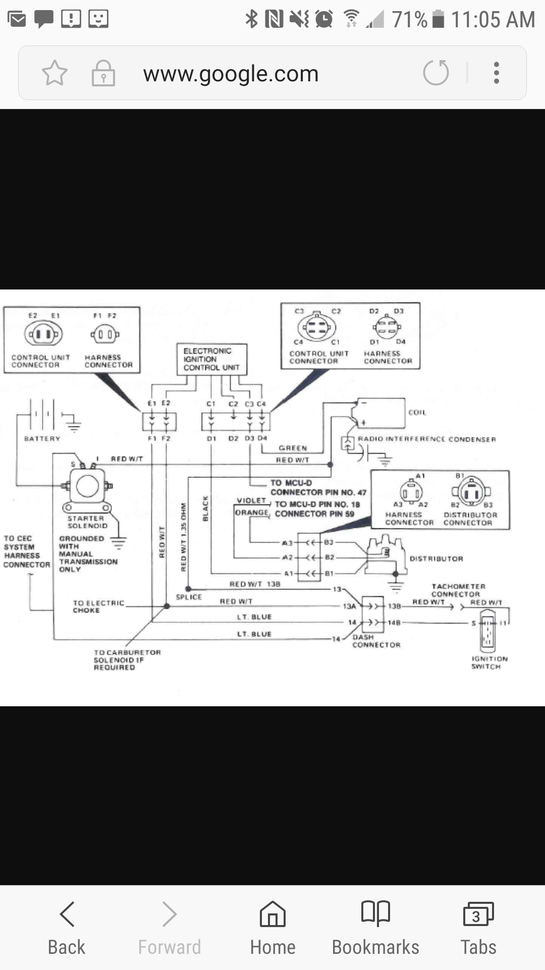
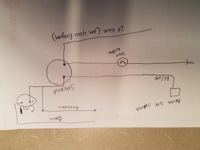
I found the pic (full pic) I left it in "MS Paint" (see pics)

Page 2 showed with your pics!

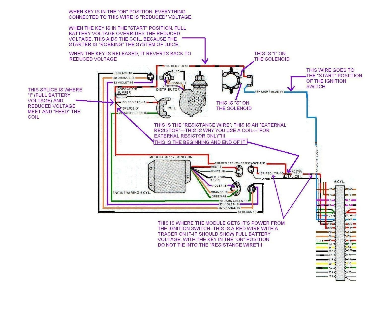
Looks as though your Baby is a '84 with a '79 engine (knew this).

It (the engine) needs to be wired like a '79 to eliminate the new crap (computer)

WE ARE NOT GONNA JUST WHACK ALL THE WIRES OFF OF IT AND SLING IT IN THE WOODS!

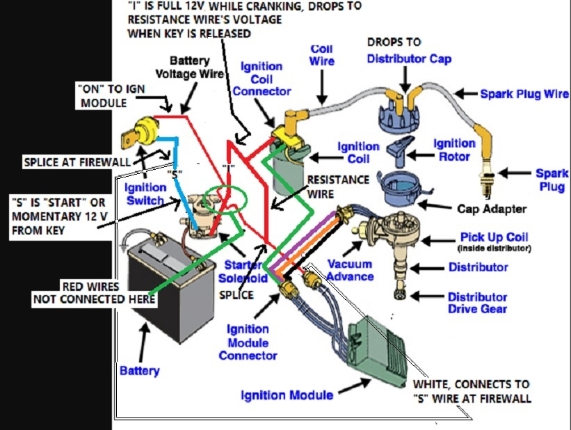
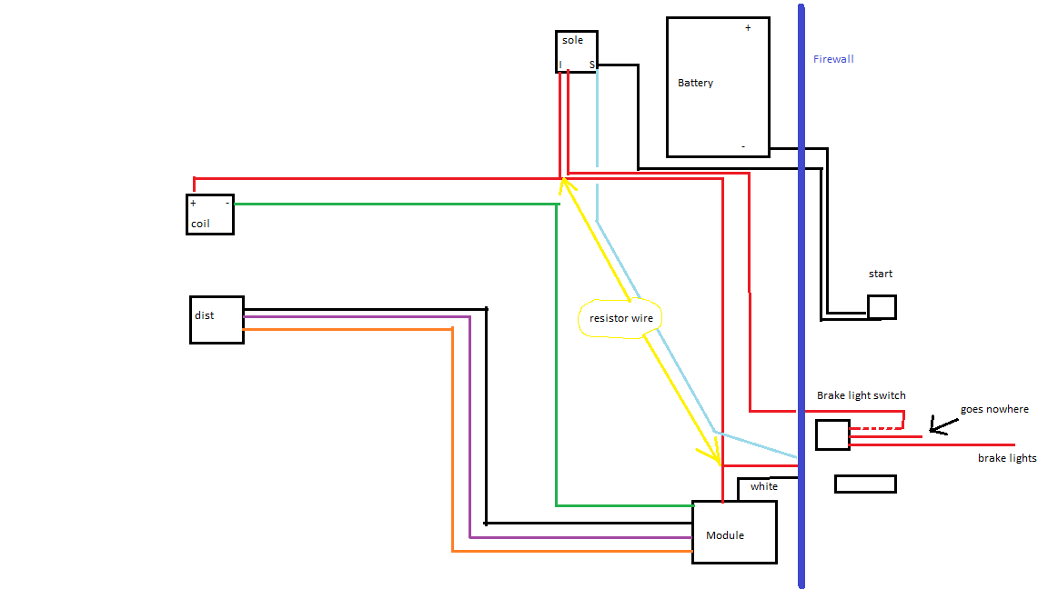
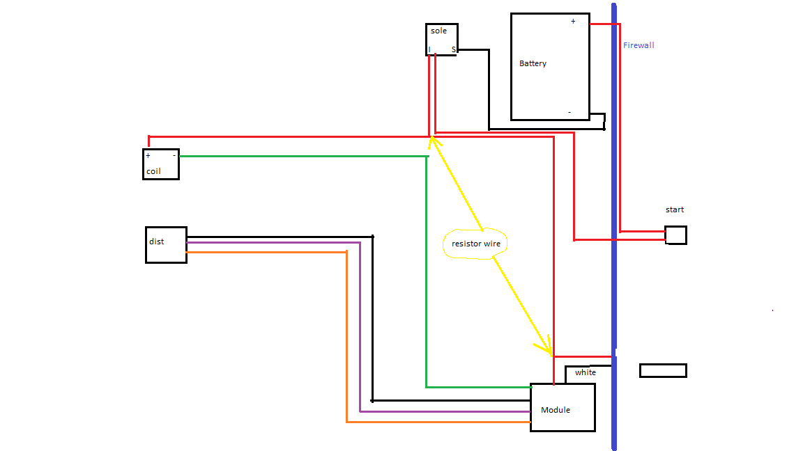
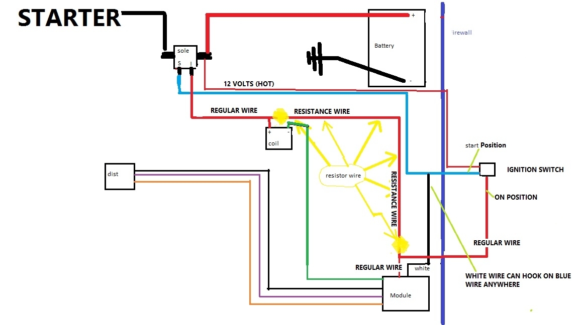
We need to pretty much make it look like the diagram below, Actually my 2nd diagram below (same thing as 1st)

We will eliminate the module wires going in and out of the firewall (cut and cap off/ tape off these wires)

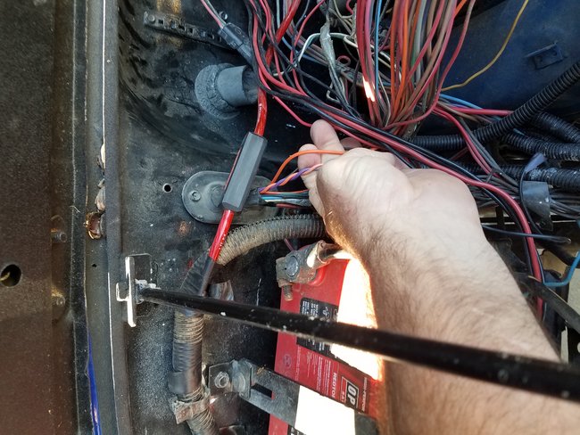
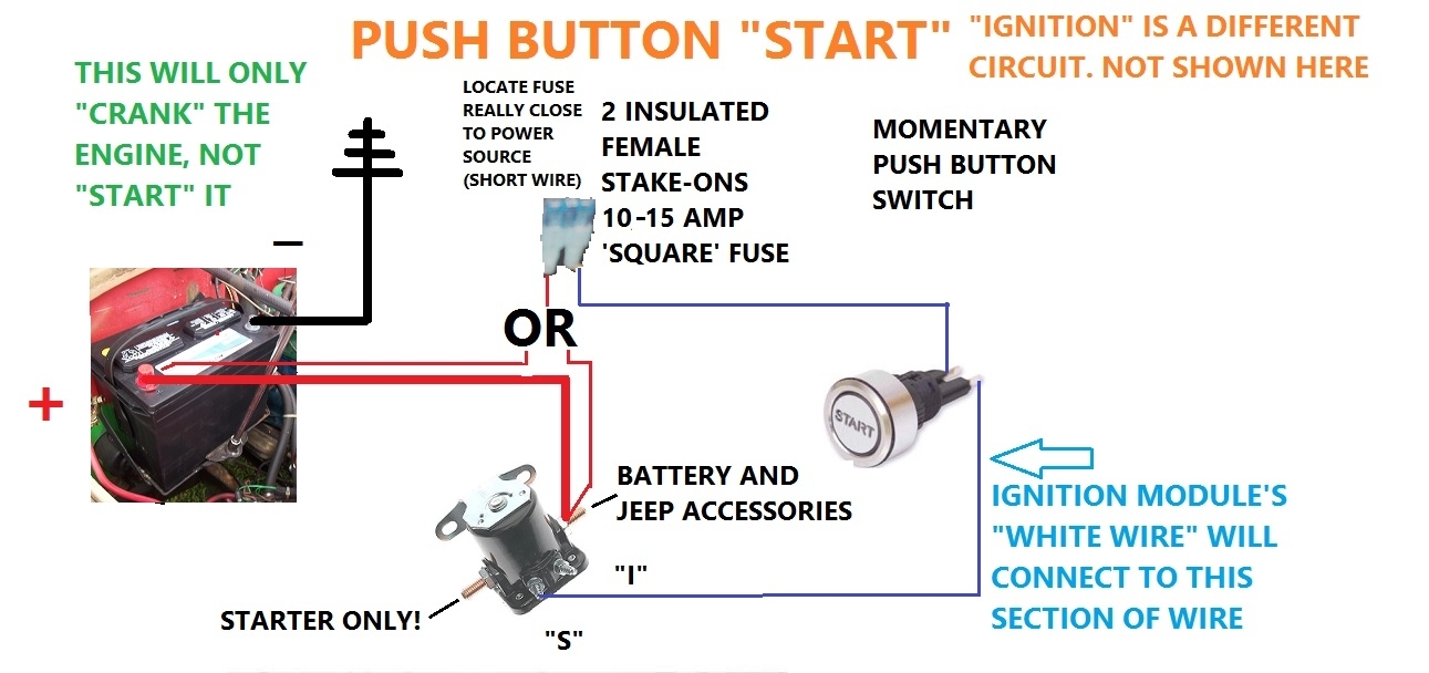
2nd diagram- see the Blue Wire? Follow it to (My/ 6 cyl) firewall. See that the white module wire connects to it at the firewall?

Now "hands on" your Blue Wire on the Jeep at the solenoid, Follow it to the firewall (this eventually runs to the IGN switch to "START"). The WHITE WIRE to the Module will hook onto it, anywhere! Before it goes into the firewall. Pick a good out of the way anti-rats nest place to tie it in!

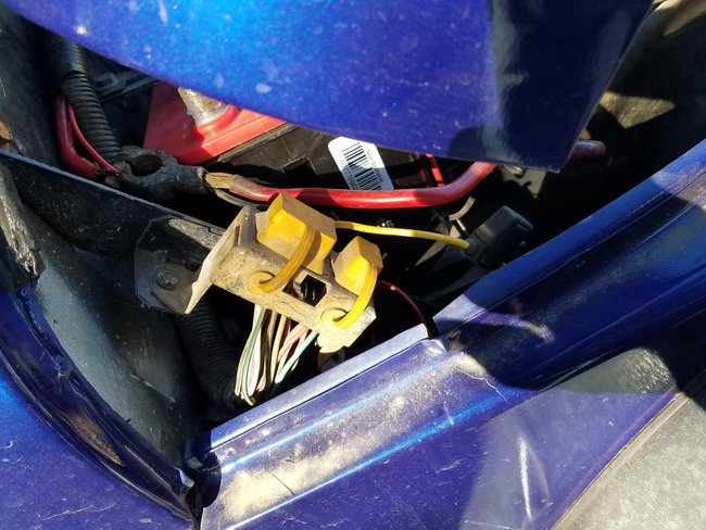
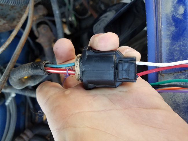
Your MODULE has 4 wires coming out? And 2 IN?

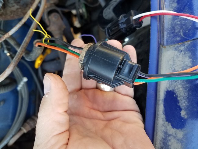
Send me a pic of the Module including the ends same with the distributor (end included)

I will use those pics to show you how to make nice splices and no crappy connections in order to keep all of this wiring in the engine compartment! (Not going to the computer!)

We will get the missing wires back in place to match the '79 diagram.

I'll spend the time to help/ must keep wife's Honey-Dos at bay!

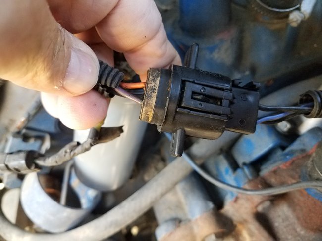
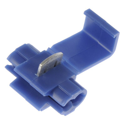
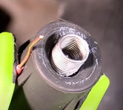
Ever use 3rd pic connectors?

Your Turn

The Medic
Was this
answer
helpful?
Yes
No
+1
Sunday, April 23rd, 2017 AT 11:31 AM
Tiny
RICKB8479
  • MEMBER
  • 21 POSTS
Cant see your reply
Was this
answer
helpful?
Yes
No
Sunday, April 23rd, 2017 AT 12:28 PM
Tiny
RICKB8479
  • MEMBER
  • 21 POSTS
Got it
Was this
answer
helpful?
Yes
No
Sunday, April 23rd, 2017 AT 12:31 PM
Tiny
RICKB8479
  • MEMBER
  • 21 POSTS
So I wred it up like you said it started right up. Thanks.

Now a new problem. After I shut it off and cleaned up all the wiring under the hood went to start it now it wont crank. Ill send a diagram of what I have tomorrow. Thanks again.
Was this
answer
helpful?
Yes
No
Sunday, April 23rd, 2017 AT 6:40 PM
Tiny
RICKB8479
  • MEMBER
  • 21 POSTS
I guess at this point maybe you can just tell me how to rewire the start cicuit. What do you think? Thanks for all the assistance with the ignition. Real bummer that I have it running but now it won't crank.
Was this
answer
helpful?
Yes
No
Monday, April 24th, 2017 AT 8:07 AM
Tiny
RICKB8479
  • MEMBER
  • 21 POSTS
The first pic is what I have now. The second pic is what I propose for a fix. Will it work?

What does the light blue actually do?
Was this
answer
helpful?
Yes
No
Monday, April 24th, 2017 AT 2:32 PM
Tiny
CJ MEDEVAC
  • MECHANIC
  • 11,004 POSTS
More like this!

See how I modified your pic below

The big thing is, the 4 wires from the IGN Module, go to their respective spots, and no where else along the way.

If you have to splice the Purple wire into place, do it! (Reason I asked if you had ever used the 'Piggy-Back' Splices in previous answer)

Cut loose anything that is not supposed to be there!

Blue comes from switch, when turned to 'start' it activates the solenoid allowing the pos battery cable to flow thru to the starter. When the key is released, the blue wire goes dead and the solenoid quits allowing the starter to turn (in hopes that the engine has started)

At the same time "I" gets full battery voltage, it overrides the low voltage resistance wire (only during cranking) This aids in 'start-up', as the starter is robbing the power at this time.

The Medic
Was this
answer
helpful?
Yes
No
Monday, April 24th, 2017 AT 6:38 PM
Tiny
CJ MEDEVAC
  • MECHANIC
  • 11,004 POSTS
Trying your pic again?

The Medic
Was this
answer
helpful?
Yes
No
Monday, April 24th, 2017 AT 6:39 PM
Tiny
CJ MEDEVAC
  • MECHANIC
  • 11,004 POSTS
OK,

Here's a diagram I made for a momentary contact push button switch.

I also added on where your Ignition Module "white wire" should connect.

The Medic
Was this
answer
helpful?
Yes
No
Saturday, April 29th, 2017 AT 10:11 PM

Please login or register to post a reply.

Sponsored links