Good morning,
The 700 is an information code that indicates another code is set in the transmission.
The 751 is for the 1-2 shift solenoid. I attached the description below for you and the description.
https://www.2carpros.com/articles/automatic-transmission-problems
I would start by changing the fluid and filter as there may be some dirt or debris in the system.
https://www.2carpros.com/articles/how-to-service-an-automatic-transmission
Beyond that I attached a lot of information for you for the replacement of the solenoid.
Roy
Circuit/System Description
The 1-2 shift solenoid (SS) valve and the 2-3 SS valve are supplied with fused ignition voltage. The ground path is controlled by the transmission control module (TCM). When the TCM commands the solenoid OFF, a ground path is not provided and the filtered line pressure that is fed to the solenoid is exhausted. When the TCM commands the solenoid ON, a ground path is provided and the exhaust port is blocked, stopping the exhaust of line pressure. The TCM identifies a 1-2 SS valve or a 2-3 SS valve condition by monitoring the commanded gear versus gear ratio. Refer to Shift Solenoid Valve State and Gear Ratio (See: Automatic Transmission/Transaxle > Mechanical > Shift Solenoid Valve State and Gear Ratio).
Conditions for Running the DTC
P0751
No TP sensor DTCs P0121, P0122, or P0123.
No ISS DTCs P0716 or P0717.
No OSS DTCs P0722 or P0723.
No TCC system stuck ON DTC P0742.
No 1-2 SS valve electrical DTCs P0973 or P0974.
No 2-3 SS valve electrical DTCs P0976 or P0977.
The calc. throttle position is 8 percent or more.
The transmission ISS is 150 RPM or more.
The transmission OSS is 200 RPM or more.
The time since the last gear change is 1 second.
The engine speed is greater than 500 RPM for 5 seconds.
The transmission fluid temperature is between 20-130°C (68-266°F).
The engine torque is greater than 50 Nm (37 lb ft).
P0752
No TP sensor DTCs P0121, P0122, or P0123.
No ISS DTCs P0716 or P0717.
No OSS DTCs P0722 or P0723.
No TCC system stuck ON DTC P0742.
No 1-2 SS valve electrical DTCs P0973 or P0974.
No 2-3 SS valve electrical DTCs P0976 or P0977.* The calc. throttle position is 8 percent or more.
The transmission ISS is 150 RPM or more.
The transmission OSS is 200 RPM or more.
The engine torque is greater than 50 Nm (37 lb ft).
The time since the last gear change is 1 second.
The engine speed is greater than 500 RPM for 5 seconds.
The transmission fluid temperature is between 20-130°C (68-266°F).
Conditions for Setting the DTC
P0751
The following conditions both occur twice in one trip:
P0751 - Condition 1
The TCM commands 1st gear and the gear ratio indicates 2nd gear, 1.54:1 to 1.71:1. for 2 seconds.
P0751 - Condition 2
The TCM commands 4th gear and the gear ratio indicates 3rd gear, 0.95:1 to 1.05:1, for 4 seconds.
P0752
The following conditions both occur twice in one trip:
P0752 - Condition 1
The TCM commands 2nd gear and the gear ratio indicates 1st gear, 2.81:1 to 3.11:1 for 2 seconds.
P0752 - Condition 2
The TCM commands 3rd gear and the gear ratio indicates 4th gear, 0.65:1 to 0.72:1, for 3 seconds.
Action Taken When the DTC Sets
P0751
DTC P0751 is a Type B DTC.
The TCM commands maximum line pressure.
The TCM freezes transmission adaptive functions.
P0752
DTC P0752 is a Type B DTC.
The TCM inhibits 3-2 downshifts when the vehicle speed is greater than 52 km/h (32 mph).
The TCM forces the TCC ON.
The TCM commands maximum line pressure.
The TCM freezes transmission adaptive functions.
Conditions for Clearing the DTC
DTCs P0751 and P0752 are Type B DTCs.
Diagnostic Aids
If the DTC is cleared, then will not reset when the vehicle is driven, some of the following conditions may exist:
Fluid contamination
Plugged fluid circuits
Restricted fluid circuits
Inspect transmission fluid lines to radiator. Lines may be pinched, plugged or twisted.
Refer to Shift Solenoid Valve State and Gear Ratio (See: Automatic Transmission/Transaxle > Mechanical > Shift Solenoid Valve State and Gear Ratio).
Internal damage to the torque converter may prevent TCC application.
It is possible for an internal TCM failure which may not allow sufficient current to operate the solenoids. Verify TCM functionality by commanding the suspected solenoid ON/OFF using the scan tool and listen for a click.
Reference Information
Schematic Reference
Automatic Transmission Controls Schematics (See: Automatic Transmission/Transaxle > Electrical)
Connector End View Reference
Component Connector End Views (See: Vehicle > Connector Views)
Electrical Information Reference
Circuit Testing (See: Vehicle > Component Tests and General Diagnostics)
Connector Repairs (See: Vehicle > Component Tests and General Diagnostics)
Testing for Intermittent Conditions and Poor Connections (See: Vehicle > Component Tests and General Diagnostics)
Wiring Repairs (See: Vehicle > Component Tests and General Diagnostics)
DTC Type Reference
Powertrain Diagnostic Trouble Code (DTC) Type Definitions (See: A L L Diagnostic Trouble Codes ( DTC ) > Diagnostic Trouble Code Descriptions)
Scan Tool Reference
Control Module References (See: Vehicle > Programming and Relearning) for scan tool information
Circuit/System Verification
1. Perform the Transmission Fluid Check (See: Fluid - A/T > Component Tests and General Diagnostics > Transmission Fluid Checking Procedure) to verify correct fluid level and condition. The transmission fluid level should be within the crosshatch band and the transmission fluid should be red or dark brown.
If the transmission fluid is low or discolored, refer to Automatic Transmission Fluid Filter and Seal Replacement (See: Fluid Filter - A/T > Removal and Replacement > Automatic Transmission Fluid Filter and Seal Replacement).
2. Operate the vehicle in Drive and ensure that the TCM commands all gears. The ratios should match the commanded gear for all gears. Refer to Shift Solenoid Valve State and Gear Ratio (See: Automatic Transmission/Transaxle > Mechanical > Shift Solenoid Valve State and Gear Ratio).
If the gear ratios do not match the commanded gear, inspect the following and repair/replace as necessary:
Inspect the shift solenoid/hydraulic circuit for an internal malfunction.
Damaged seals on the shift solenoid valve. Refer to Shift Solenoid Leak Test (See: Automatic Transmission/Transaxle > Component Tests and General Diagnostics > Shift Solenoid Leak Test) for further diagnosis.
3. Operate the vehicle within the Conditions for Running the DTC. You may also operate the vehicle within the conditions that you observed from the Freeze Frame/Failure Records data.
Repair Instructions
Perform the Diagnostic Repair Verification (See: A L L Diagnostic Trouble Codes ( DTC ) > Verification Tests) after completing the repair.
Shift Solenoid Leak Test (See: Automatic Transmission/Transaxle > Component Tests and General Diagnostics > Shift Solenoid Leak Test)
1-2 Shift Solenoid Valve Replacement (See: Shift Solenoid, A/T > Removal and Replacement > 1-2 Shift Solenoid Valve Replacement)
Control Valve Body Disassemble (See: Automatic Transmission/Transaxle > Overhaul)
Control Valve Body Cover Removal (See: Automatic Transmission/Transaxle > Overhaul) and Side Cover/Gaskets, Disassemble, Assemble, Install (See: Automatic Transmission/Transaxle > Overhaul)
1-2 Shift Solenoid Valve Replacement
Removal Procedure
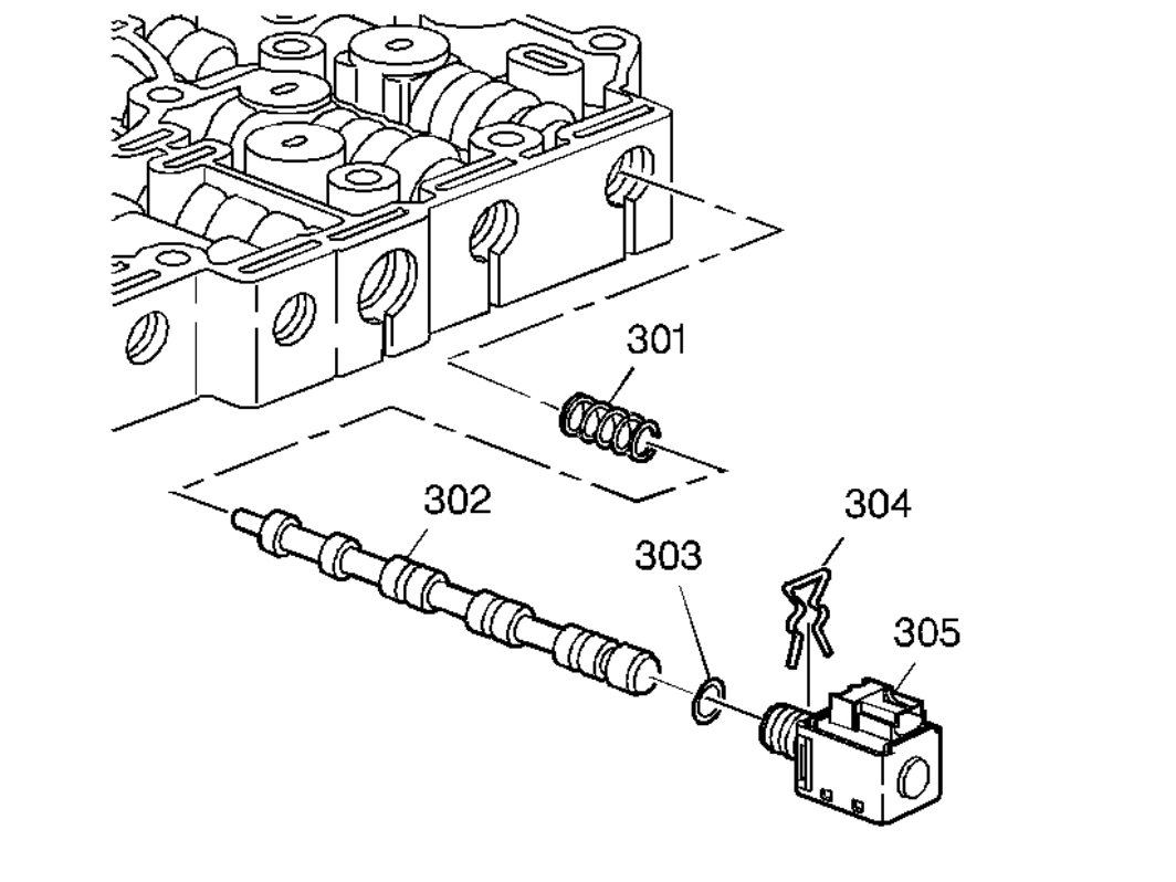
Important: Retainer clips hold in each of the valve line-ups. Use a small screwdriver in order to remove the retainer clips. Be careful not to score the valve body when removing the retainer clips and valves. Before removing the valve line-ups, inspect each valve line-up for freedom of movement.
imageOpen In New TabZoom/Print
1. Remove the transmission side cover. Refer to Control Valve Body Cover Replacement (See: Valve Body, A/T > Removal and Replacement > Control Valve Body Cover Replacement).
2. Remove the 1-2 shift solenoid retainer clip (304), the 1-2 shift solenoid (305) with O-ring (303), the 1-2 shift valve (302), and the 1-2 shift valve spring (301).
Control cover
Control Valve Body Cover Replacement
Special Tools
J 36850 Transjel Lubricant(TM)
Removal Procedure
1. With the wheels in the straight ahead position, remove the key from the ignition switch.
2. Remove the underhood electrical center cover.
3. Disconnect the negative battery cable. Refer to Battery Negative Cable Disconnection and Connection (See: Battery Cable > Removal and Replacement).
imageOpen In New TabZoom/Print
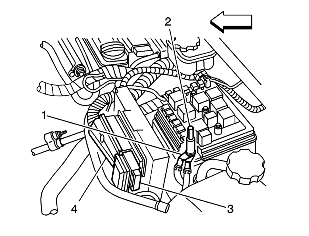
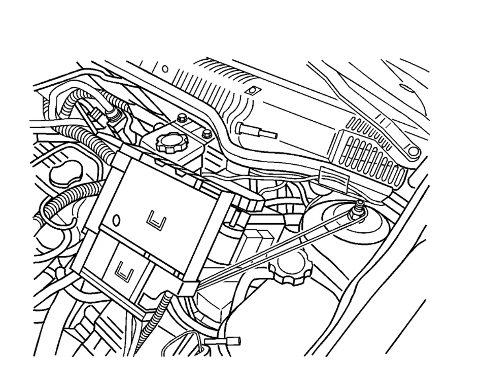
4. Disconnect the engine control module harness connector (3, 4).
5. Disconnect the positive battery cables (1) from the under hood electrical center.
imageOpen In New TabZoom/Print
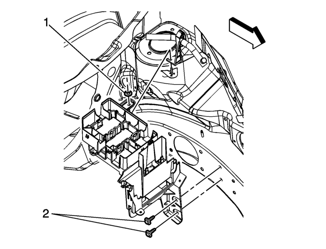
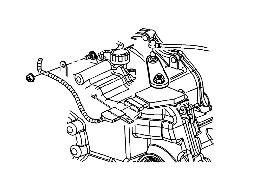
6. Remove the underhood electrical center tray bracket nuts (1) and bolt (2).
7. Disconnect the wiring harness retainer from the tray bracket.
imageOpen In New TabZoom/Print
8. Lift the electrical center up and swing it back and out of the way.
imageOpen In New TabZoom/Print
9. Disconnect the shift cable from the PNP switch.
10. Disconnect the electrical connector from the PNP switch.
11. Remove the shift cable with bracket from the transmission.
12. Remove the PNP switch. Refer to Park/Neutral Position Switch Replacement (See: Transmission Position Sensor/Switch, A/T > Removal and Replacement > Park/Neutral Position Switch Replacement).
13. Install the engine support fixture. Refer to Engine Support Fixture (See: Engine > Removal and Replacement > Engine Support Fixture) for the 2.0L engine or Engine Support Fixture (See: Engine > Removal and Replacement > Engine Support Fixture) for the 2.2L or 2.4L engine.
14. Secure the cooling module to the upper body structure.
15. Raise the vehicle. Refer to Lifting and Jacking the Vehicle (See: Vehicle Lifting > Procedures).
16. Remove the front tires and wheels. Refer to Tire and Wheel Removal and Installation (See: Wheels and Tires > Removal and Replacement > Tire and Wheel Removal and Installation).
17. Remove the frame. Refer to Frame Replacement (See: Front Subframe > Removal and Replacement > Frame Replacement).
18. Remove the left wheel drive shaft from the transaxle. Refer to Wheel Drive Shaft Replacement (See: Axle Shaft Assembly > Removal and Replacement > Wheel Drive Shaft Replacement).
19. Lower the vehicle.
20. Remove the left transmission mount. Refer to Transmission Mount Replacement - Left Side (See: Transmission Mount, A/T > Removal and Replacement > Transmission Mount Replacement - Left Side).
21. Lower the engine with the engine support fixture.
22. Raise the vehicle. Refer to Lifting and Jacking the Vehicle (See: Vehicle Lifting > Procedures).
imageOpen In New TabZoom/Print
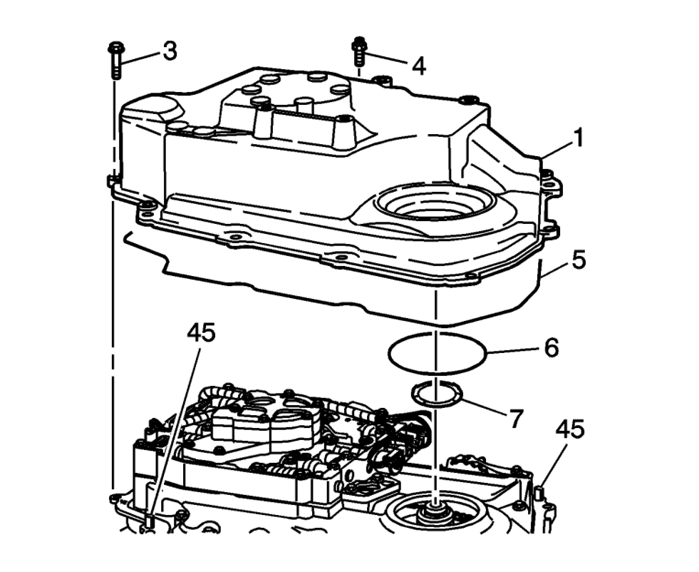
23. Remove the 11 transmission side cover bolts (3) or studs (4) (model dependant).
Caution: Pry on the corner of the case side cover near the locating dowel pins (45), to prevent damage to the sealing surfaces.
24. Remove the transmission side cover (1).
25. Remove the two side cover gaskets (5 and 6) and the side cover to driven support thrust washer (7). They may remain with the side cover. Only replace if necessary.
Images (Click to enlarge)
Nov 15, 2020 at 2:55 AM