Horn not functioning

Tiny
TBIRD7778
  • MEMBER
  • 1994 FORD F-150
  • 220,000 MILES
My horn isn' working on my truck. I have used one of your diagrams you posted for a different question and tried to follow the wires to see where I am losing power.

Here is what I have tried thus far:

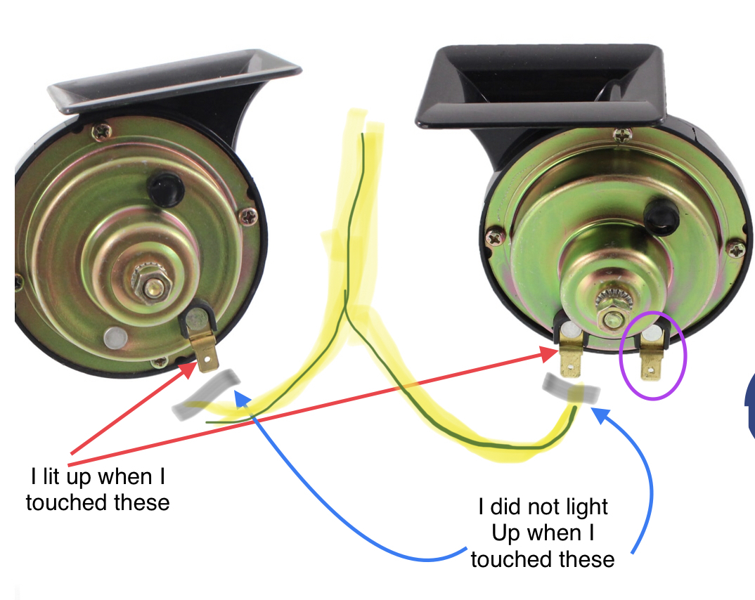
1. At the horn - yellow/light green wire - pulled both connectors - probed the clips with the light circuit tester - tester did not light up.
2. At the harness under the driver side panel (coming in from the hood) - peeled back insulation and probed the wire with light circuit tester - tester did not light up.
3. Found clip under steering holding the dark blue wire - probed the hole of dark blue wire with light circuit tester - tester lit up.
4. Turquoise Blue box under the dash above the gas pedal (I think it's the airbag module - peeled back the insulation on yellow/light green wire and tested with light circuit test - tester lit up.
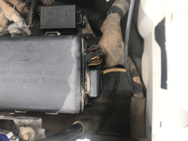
5. Power Distribution Fuse Box under the hood - tested Fuse and Relay Ports with circuit tester - tester lit up.
6. Fuse and Relay - Fuse is good at Power Distribution Fuse box - I swapped out the Relay with one that I know is working.

After swapping out that relay - I went back and tested items 1-4 with the same results I have listed.

I know a likely option is the clock spring (as my ABS light flashes and cruise control doesn't work). However, I would like to rule all wiring issues - the people we purchased the truck from had pulled out an alarm system and left the wiring for power doors, lights, (and possibly horn) a mess.

So what do I need to try next?
Saturday, April 25th, 2020 AT 9:56 AM

16 Replies

Tiny
KASEKENNY
  • MECHANIC
  • 18,907 POSTS
To rule out wiring you simply check for continuity and or resistance from one end of the wiring to the other. So in this case, test from the switch to the fuse box. Then to the components in this diagram. Basically you want to make sure the wire is intact and if you want to load test them, they should light a headlight bulb but I don't think that is necessary on a horn circuit.

However, I would get codes first and foremost because if this is the case, I am sure they are related. We need to at least start there before you go to far down the path of wiring. The resistance or continuity test is pretty easy so if you want to confirm there are no opens, that would be fine.

https://www.2carpros.com/articles/checking-a-service-engine-soon-or-check-engine-light-on-or-flashing

https://www.2carpros.com/articles/ford-lincoln-mercury-obd1-1995-and-earlier-diagnostic-trouble-code-definition-and-retrieval
Was this
answer
helpful?
Yes
No
Saturday, April 25th, 2020 AT 12:20 PM
Tiny
TBIRD7778
  • MEMBER
  • 33 POSTS
Okay.
I tested it with a jump wire.
I think I got codes 33, 13, and 12.

I will attach the video and you can see if you think the same codes are flashing.
Was this
answer
helpful?
Yes
No
Saturday, April 25th, 2020 AT 7:41 PM
Tiny
KASEKENNY
  • MECHANIC
  • 18,907 POSTS
I see the same codes. Nothing related to the clock-spring but I want to confirm the test light testing that you did on the wiring was when you were pressing the horn pad? I know it is basic but we need to confirm that.

If so, is this what you are getting on the wiring diagram?
Was this
answer
helpful?
Yes
No
Sunday, April 26th, 2020 AT 7:03 PM
Tiny
TBIRD7778
  • MEMBER
  • 33 POSTS
No, I did not press the horn buttons at all while testing
Should i?

Yes, that’s correct on your diagram.
I didn’t test an yellow/light blue wires though.
Was this
answer
helpful?
Yes
No
Sunday, April 26th, 2020 AT 8:17 PM
Tiny
KASEKENNY
  • MECHANIC
  • 18,907 POSTS
Yes. Let's go straight to the horns and check voltage at the horns while pressing the horn pad.

Take a look at the wiring diagram. When you press the horn pad you are basically just closing the circuit. In order to complete the circuit you need a path to ground. Closing the circuit with the horn pad it gives it the path to ground through the horns. If you look at the symbols of the horns you will see little ground symbols at the horns. This means the horns are the ground source so we need to track the voltage through the circuit to find where it is not. Number 1 is the horn pad. If you have voltage going into the pad then that is good. Push the pad and go to number 2 where when you push the pad it energizes the relay and it closes it sending voltage to number 3. If you have voltage at number 3 then the horns are the issue. That is why we need to just jump to the horns and measure voltage when pressing the horn pad.

Let me know if this makes sense. Thanks
Was this
answer
helpful?
Yes
No
Monday, April 27th, 2020 AT 10:22 AM
Tiny
TBIRD7778
  • MEMBER
  • 33 POSTS
Okay. I tested at the horns and they light up. The wires that plug into the horn do not light up.
Was this
answer
helpful?
Yes
No
Tuesday, April 28th, 2020 AT 1:08 PM
Tiny
TBIRD7778
  • MEMBER
  • 33 POSTS
I checked the wires on the fender side of the power dist. Box under hood. The yellow/green no light - the yellow/blue lit up.
Was this
answer
helpful?
Yes
No
Tuesday, April 28th, 2020 AT 1:44 PM
Tiny
KASEKENNY
  • MECHANIC
  • 18,907 POSTS
Okay. I am a little confused. You said you tested at the horns and it lit the lamp but the wires did not light the lamp?

Then if you have power on the wire going to the relay but none coming out then you either have a wiring issue or the relay is faulty.

I may be misunderstanding it so correct me where I am wrong. Thanks
Was this
answer
helpful?
Yes
No
Wednesday, April 29th, 2020 AT 5:43 PM
Tiny
TBIRD7778
  • MEMBER
  • 33 POSTS
I attached pictures of new horns that might help explain what I did. When I touched the little pegs on the horn, the lamp lit up, but when I disconnected the yellow/green wires and probes inside the connector that attached to the pegs, the lamp did not light up.
One thing I noticed on this new horn is that one of the horns has 2 pegs.I don’t remember mine having one with 2 pegs. I didn’t see any other wires coming out of horn but it’s so hard to see much less get to; maybe there was another peg that I didn’t see.
Was this
answer
helpful?
Yes
No
Wednesday, April 29th, 2020 AT 8:23 PM
Tiny
TBIRD7778
  • MEMBER
  • 33 POSTS
Is there another horn relay other than the one in the power distribution box? If so, where?
Was this
answer
helpful?
Yes
No
Wednesday, April 29th, 2020 AT 8:24 PM
Tiny
TBIRD7778
  • MEMBER
  • 33 POSTS
Also, I don’t know if I am testing the correct places you show on your diagram. I don’t know if I know exactly where the items are that you have labeled #1 and #2.
Was this
answer
helpful?
Yes
No
Wednesday, April 29th, 2020 AT 8:27 PM
Tiny
KASEKENNY
  • MECHANIC
  • 18,907 POSTS
Okay. Let's try something because I think I am confused now on how you are testing these.

Unplug both horns and jump 12 volts to the three tabs one at a time. I marked on your drawing just to show this. The horns should blow when you touch 12 volts to them. If they don't then the horns are the issue.

If you are not sure how to jump this just run a wire from the battery positive post and touch it to these tabs. Let me know what you find. Thanks

Forgot to add, there are no other relays for the horns. Just the one in the engine fuse box.
Was this
answer
helpful?
Yes
No
Friday, May 1st, 2020 AT 8:34 AM
Tiny
TBIRD7778
  • MEMBER
  • 33 POSTS
Okay.
I checked and I only have one peg on each horn.
I tested them to the battery and they both honked Individually and together.

What is supposed to hook up to that third peg? And is it necessary?
Was this
answer
helpful?
Yes
No
Friday, May 1st, 2020 AT 12:10 PM
Tiny
KASEKENNY
  • MECHANIC
  • 18,907 POSTS
The second peg is not needed. It is probably just to run from the first horn to the second. Most only use the first and just splice off of that. If both horns work that is all we needed for this step.

Next step is to test the rest of the system without the relay in the picture. So here is what we need to do with referring to the wiring diagram. Remove the relay and check for voltage on each of the terminals in the fuse box (not the relay). You should have voltage (12 volts) on pin 3 and 4 all the time. You should not have voltage on 1 and 2 with the relay out.

Let's start with getting a wire or a paper clip and jump number 3 to number 2 and the horns should sound.

Let me know if works and that will prove all wiring from the relay to the horns. After that we can take the next step.

Lastly, did the horns just stop working one day or have they not been working for a while?
Was this
answer
helpful?
Yes
No
Saturday, May 2nd, 2020 AT 8:58 AM
Tiny
TBIRD7778
  • MEMBER
  • 33 POSTS
Yes, the horn sounds when jump those. It has not worked since got it several months ago.
Was this
answer
helpful?
Yes
No
Monday, May 4th, 2020 AT 5:01 PM
Tiny
KASEKENNY
  • MECHANIC
  • 18,907 POSTS
Okay. That proves out all the wiring from the relay. As long as you are sure that the relay that you swap was a good relay, then the horn switch or the wiring to it is the issue. If you want to unhook the inline connector from the relay to the horn switch and ground the dark blue wire then the horn should sound. Notice how this wiring diagram shows that you should have 0V at the switch when the horn is depressed. This is basically your ground to ground the relay.

Now that we have worked through all this, your initial concern may be accurate. It is either the horn pad, clock-spring, or wiring that they messed up. Again, if you want to test all this portion, you can unhook the horn switch and run a jumper wire from the switch to this same inline connector between the relay and horn switch and that will prove the switch is okay, the wiring from the connector to the relay, the relay and all the wiring from the relay to the horns and the horns themselves are good. Leaving just the wiring from the switch to the connector.

Keep in mind, you have already proven the relay (again assuming it was a good relay that you swapped) and the wiring from the relay to the horns and horns themselves are all good. You are just left with the switch side of the relay to prove out and doing this process will tell us where the issue is.
Was this
answer
helpful?
Yes
No
Monday, May 4th, 2020 AT 7:30 PM

Please login or register to post a reply.

Sponsored links