Heated/cooled seats not working

Tiny
DEWMOB
  • MEMBER
  • 2014 LINCOLN MKZ
  • 60,000 MILES
The touch screen shows the heating or cooling being activated but neither work. This is for both front seats. The heated steering wheel and the rear seat heaters work. I am thinking control module because it is both front seats and both heating and cooling.
Tuesday, November 20th, 2018 AT 5:11 PM

10 Replies

Tiny
JACOBANDNICKOLAS
  • MECHANIC
  • 108,269 POSTS
Hi and thanks for using 2CarPros.

The first thing I need checked is fuse number 65 in the under hood power distribution box. That one fuse will either be a 20 amp or a 30 amp. If it is bad, only replace it with what is removed. That fuse is what sends power to the module and then to both front seats only. That is why I am questioning it. Since both stopped at the same time, I doubt it is the module, but anything is possible.

I attached a segment of the wiring schematic so you can see the fuse and where the wiring splices together to provide power to both seats. To access fuse 65, do the following:

There are fuses located on the bottom of the fuse box. To access the bottom of the fuse box, do the following:

1. Release the two latches, located on both sides of the fuse box. (pic 2)
2. Raise the inboard side of the fuse box from the cradle.
3. Move the fuse box toward the center of the engine compartment.
4. Pivot the outboard side of the fuse box to access the bottom side.

See pic 4 for fuse 65 location.

Here are a couple general links that discuss replacing and checking fuses. Also, I attached one that describes how to use a test light.

https://www.2carpros.com/articles/how-a-car-fuse-works

https://www.2carpros.com/articles/how-to-check-a-car-fuse

https://www.2carpros.com/articles/how-to-use-a-test-light-circuit-tester

It is funny you are having this issue. Today, I had a 2015 Mustang in for the same problem. This may become a common issue. Today, the repair was just a fuse. I hope it is the same for you.

Let me know what you find.

Joe
Was this
answer
helpful?
Yes
No
+2
Tuesday, November 20th, 2018 AT 8:28 PM
Tiny
DEWMOB
  • MEMBER
  • 5 POSTS
I pulled fuse 65 and continuity tested, it is good.
Was this
answer
helpful?
Yes
No
Wednesday, November 21st, 2018 AT 9:58 AM
Tiny
DEWMOB
  • MEMBER
  • 5 POSTS
Also checked power at the prongs for fuse 65 and have 13dcv.
Was this
answer
helpful?
Yes
No
Wednesday, November 21st, 2018 AT 10:00 AM
Tiny
JACOBANDNICKOLAS
  • MECHANIC
  • 108,269 POSTS
Okay, since you lost power to both seats at the same time, the problem has to be either before the splice (but after the fuse) or the module has failed. I need to know what engine this has, if it is a hybrid, and any specific information you can provide. There are three different splice schematics and locations change based on the engine.

Let me know.
Was this
answer
helpful?
Yes
No
-2
Wednesday, November 21st, 2018 AT 1:42 PM
Tiny
DEWMOB
  • MEMBER
  • 5 POSTS
It is not the hybrid. It is the 3.7 AWD.
Was this
answer
helpful?
Yes
No
+1
Wednesday, November 21st, 2018 AT 1:48 PM
Tiny
JACOBANDNICKOLAS
  • MECHANIC
  • 108,269 POSTS
Thanks. Before we seek out the splice, it will be easier to check pins 1 and 2 on the control module located under the center of the dash. First, disconnect the negative battery terminal. Next, disconnect the module plug. Once removed, reconnect the battery negative cable and check pins 1 and 2. They should have battery voltage all the time.

Do this and let me know what you find. Both pins have a red wire running to them. See attached picture.

Joe
Was this
answer
helpful?
Yes
No
Wednesday, November 21st, 2018 AT 3:12 PM
Tiny
DEWMOB
  • MEMBER
  • 5 POSTS
Joe, you state above to check the pins on the plug under the center of the dash. Did you mean center of the seat? Or where is the plug located. Sorry for my confusion and thanks for the help on this.
Was this
answer
helpful?
Yes
No
Wednesday, November 21st, 2018 AT 5:00 PM
Tiny
JACOBANDNICKOLAS
  • MECHANIC
  • 108,269 POSTS
Hi and no problem. It indicates the location as under the center dash area on one schematic and under and behind the seat on a different schematic. Ugh!

Here are the specific directions provided by all data. The attached pictures are a continuation of the diagnostic flow chart after the introduction, which you have already done.

Front Seats

Pinpoint Test(s)

The Heated Seats are Inoperative - Driver and Passenger

Refer to Wiring Diagrams set 119 for schematic and connector information. See: Vehicle > Electrical

Normal Operation and Fault Conditions

REFER to: Front Seats (501-10 Front Seats).

Possible Sources

- Fuse

- Wiring, terminals or connectors

- FCIM (front controls interface module)

- Touchscreen not operating correctly
Visual Inspection and Diagnostic Pre-checks

- Verify the BJB (battery junction box) fuse 65 (30A)

_______________________________

If you look at picture 4. It indicates one location. Pictures 5, 6, 7 show a seat location. It may have to do with production dates.

______________________________

Check under the seat first. It will be easier to access if it is there. Picture 2 indicates the pin outline. Also, it shows what should be found at the pins.

You may want to have the computer scanned to see if there are any trouble codes related to the unit. It will be a B code, and a basic scanner will not read them. I am starting to see that this issue is not limited to only your vehicle, but it appears to be involving many different Ford products. I did check to see if there are any technical service bulletins or recalls, but nothing at this point.

Let me know if this helps. I feel the information I'm providing is more confusing than helpful. It is because the information I have is somewhat inconsistent. Please let me know if you have questions. We will figure it out together.

Update: The last two pictures, one is the schematic and the other shows where the module should be. Locate the SCME

Take care,
Joe
Was this
answer
helpful?
Yes
No
+2
Wednesday, November 21st, 2018 AT 8:38 PM
Tiny
RPADIN
  • MEMBER
  • 1 POST
I'm having the same problem with my 2013 Lincoln MKZ 3.7 AWD. Did this fix the problem?
Was this
answer
helpful?
Yes
No
Monday, November 25th, 2019 AT 5:39 AM
Tiny
KEN L
  • MASTER CERTIFIED MECHANIC
  • 42,961 POSTS
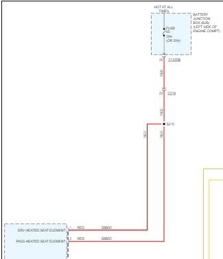
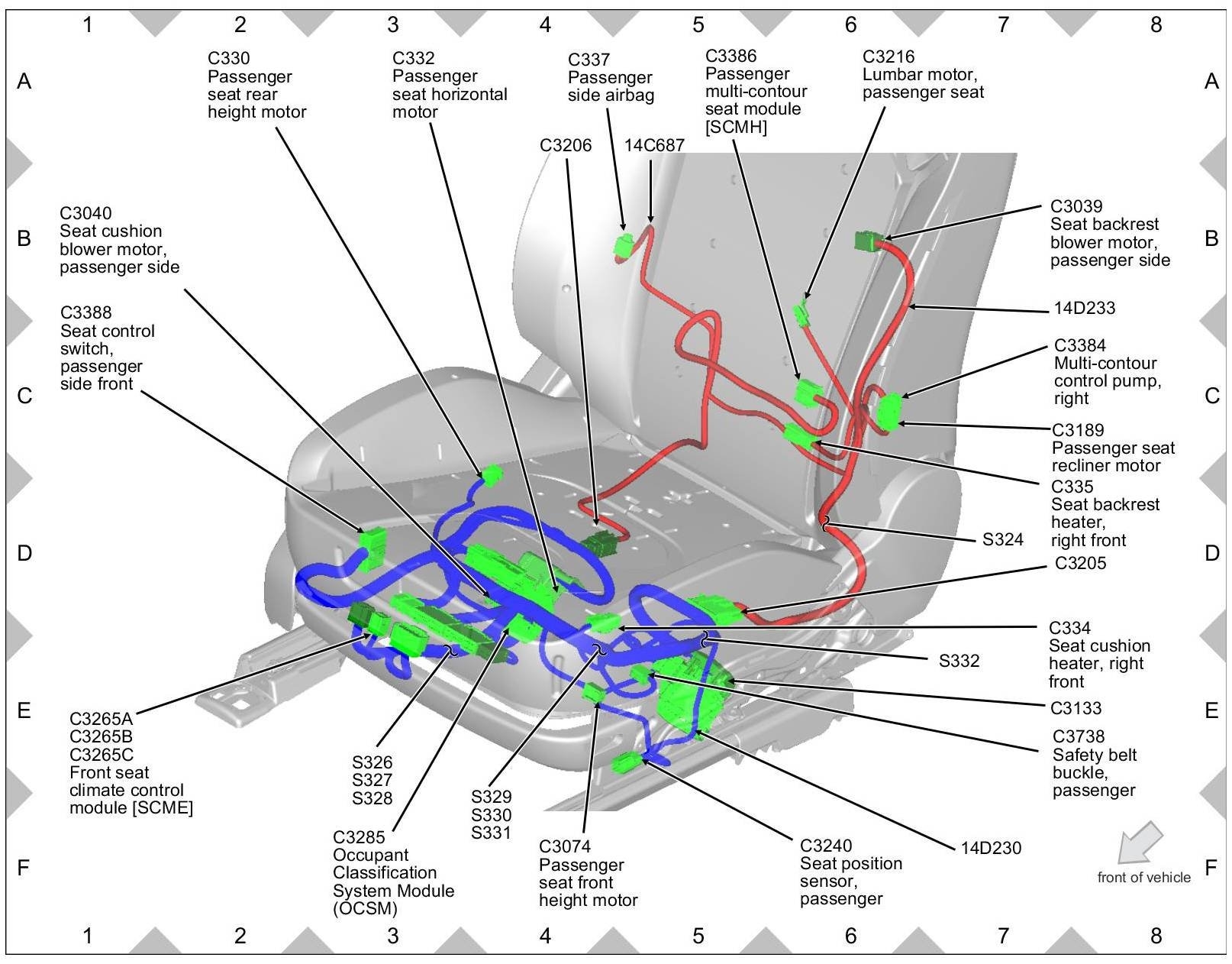
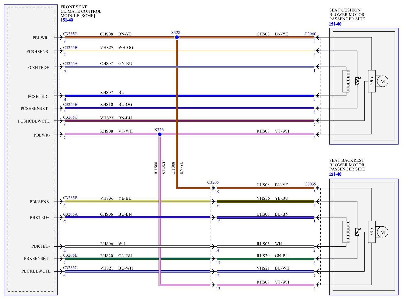
If the seat climate control module has power and ground chances are it has gone out here is a the location and the instruction on how to change it in the diagrams below.

Dual Climate Controlled Seat Module (DCSM)

Removal and Installation
NOTE: When installing a new Dual Climate Controlled Seat Module (DCSM), it is necessary to carry out Programmable Module Installation (PMI). For additional information, refer to Section 418-01 See: Information Bus > Programming and Relearning > Programmable Module Installation (PMI).
NOTE: The air bag warning indicator illuminates when the correct Restraints Control Module (RCM) fuse is removed and the ignition is ON.
NOTE: The Supplemental Restraint System (SRS) must be fully operational and free of faults before releasing the vehicle to the customer.

1. Before removing the DCSM (Dual Climate Controlled Seat Module), carry out the appropriate steps in the Programmable Module Installation (PMI) procedure. For additional information, See: Information Bus > Programming and Relearning > Programmable Module Installation (PMI).

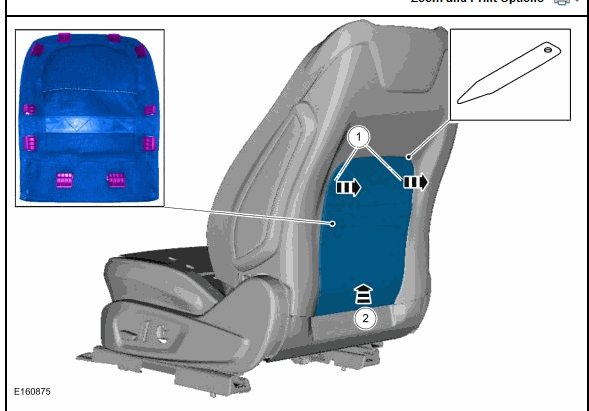
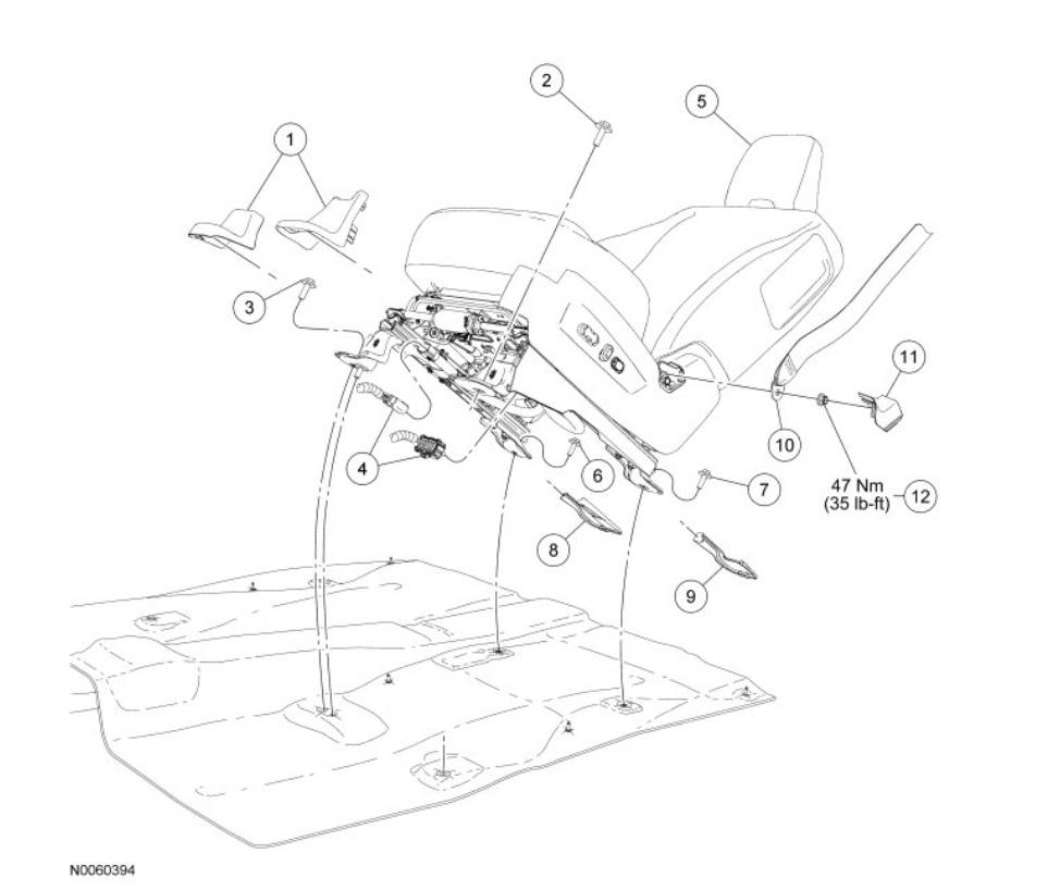
2. Remove the front passenger seat. For additional information, refer to Seat - Front See: Seats > Removal and Replacement > Seat - Front.

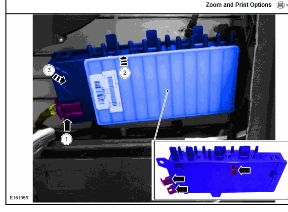
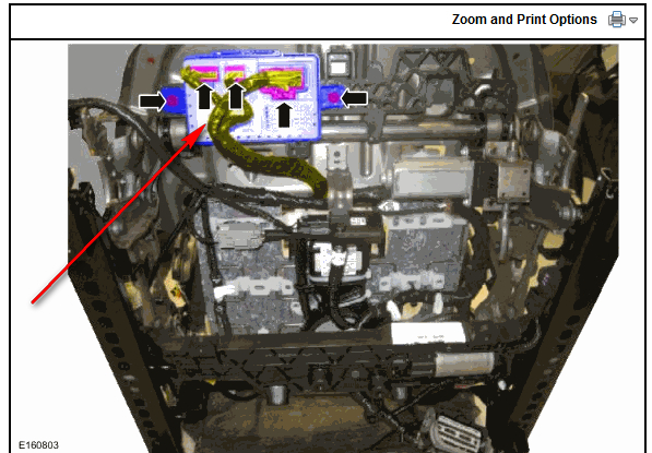
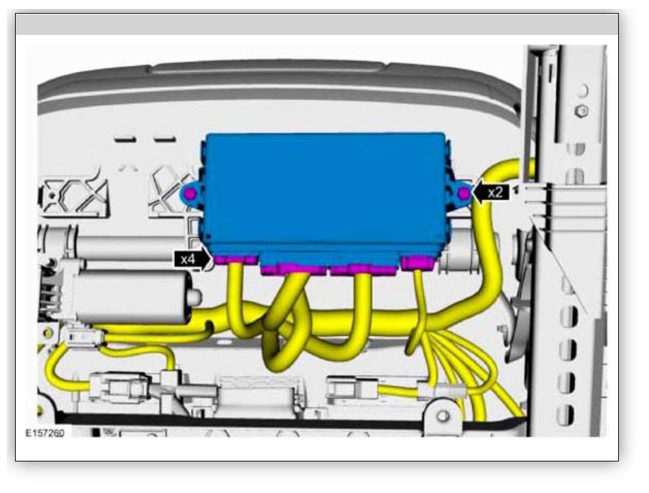
3. Remove the DCSM (Dual Climate Controlled Seat Module).
- Disconnect the 3 electrical connectors.

- Remove the 2 screws.

- Remove the DCSM (Dual Climate Controlled Seat Module).

4. To install, reverse the removal procedure.

5. Install the front passenger seat. For additional information, refer to Seat - Front See: Seats > Removal and Replacement > Seat - Front.

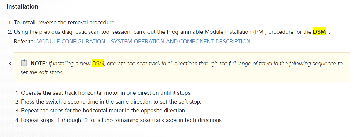
6. Install the DCSM (Dual Climate Controlled Seat Module) software data. Carry out the appropriate steps in the Programmable Module Installation (PMI) procedure. For additional information, See: Information Bus > Programming and Relearning > Programmable Module Installation (PMI).

Programmable Module Installation (PMI) Using the Integrated Diagnostic System (IDS) When the Original Module is Available
NOTE: Following module installation, some modules require a separate procedure be carried out. For instructions, refer to the specific module removal and installation procedures.

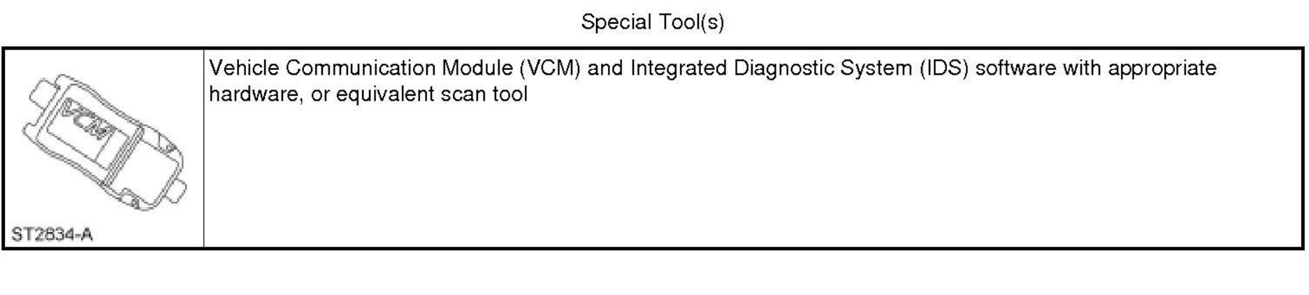
1. Connect the IDS (Integrated Diagnostic System) and identify the vehicle as normal.

2. From the Toolbox icon, select Module Programming and press the check mark.

3. Select Programmable Module Installation.

4. Select the module that is being replaced.

5. Follow the on-screen instructions, turn the ignition key to the OFF position, and press the check mark.

6. Install the new module and press the check mark.

7. Follow the on-screen instructions, turn the ignition key to the ON position, and press the check mark.

8. The IDS (Integrated Diagnostic System) downloads the data into the new module and displays Module Configuration Complete.

9. Test module for correct operation.
Programmable Module Installation (PMI) Using the Integrated Diagnostic System (IDS) When the Original Module is NOT Available
NOTE: Following module installation, some modules require a separate procedure be carried out. For instructions, refer to the specific module removal and installation procedures.

1. Install the new module.

2. Connect the IDS (Integrated Diagnostic System) and identify the vehicle as normal.

3. From the Toolbox icon, select Module Programming and press the check mark.

4. Select Programmable Module Installation.

5. Select the module that was replaced.

6. Follow the on-screen instructions, turn the ignition key to the OFF position, and press the check mark.

7. Follow the on-screen instructions, turn the ignition key to the ON position, and press the check mark.

8. If the data is not available, the IDS (Integrated Diagnostic System) displays a screen stating to contact the As-Built Data Center. Retrieve the data from the technician service publication website at this time and press the check mark.

9. Enter the module data and press the check mark.

10. The IDS (Integrated Diagnostic System) downloads the data into the new module and displays Module Configuration Complete.

11. Test module for correct operation.

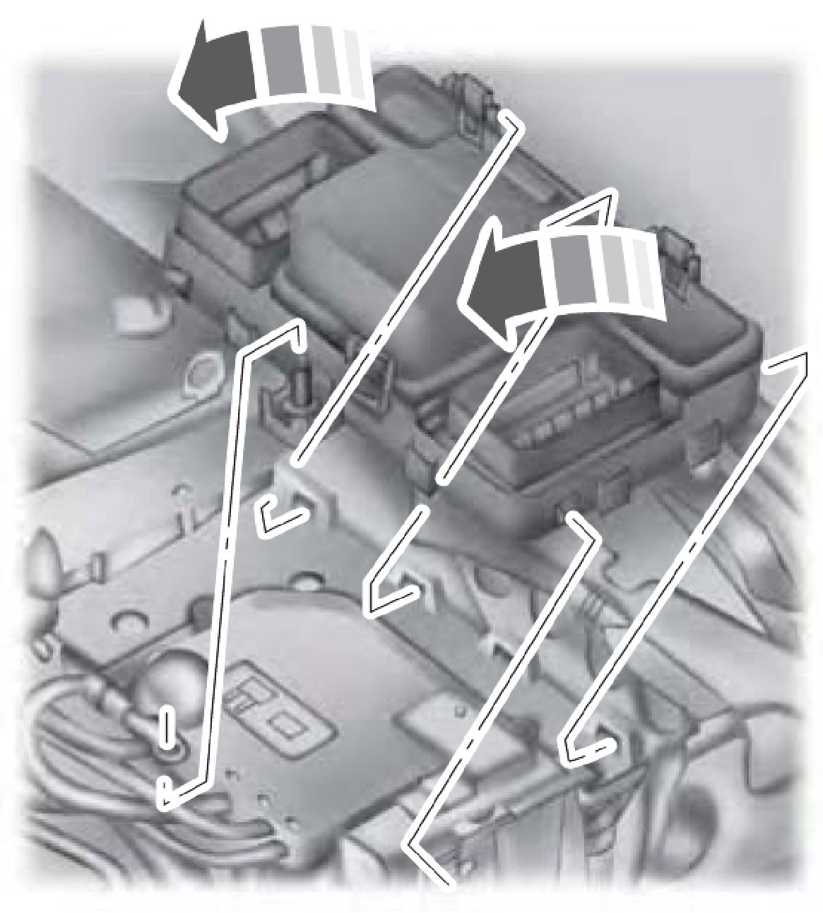
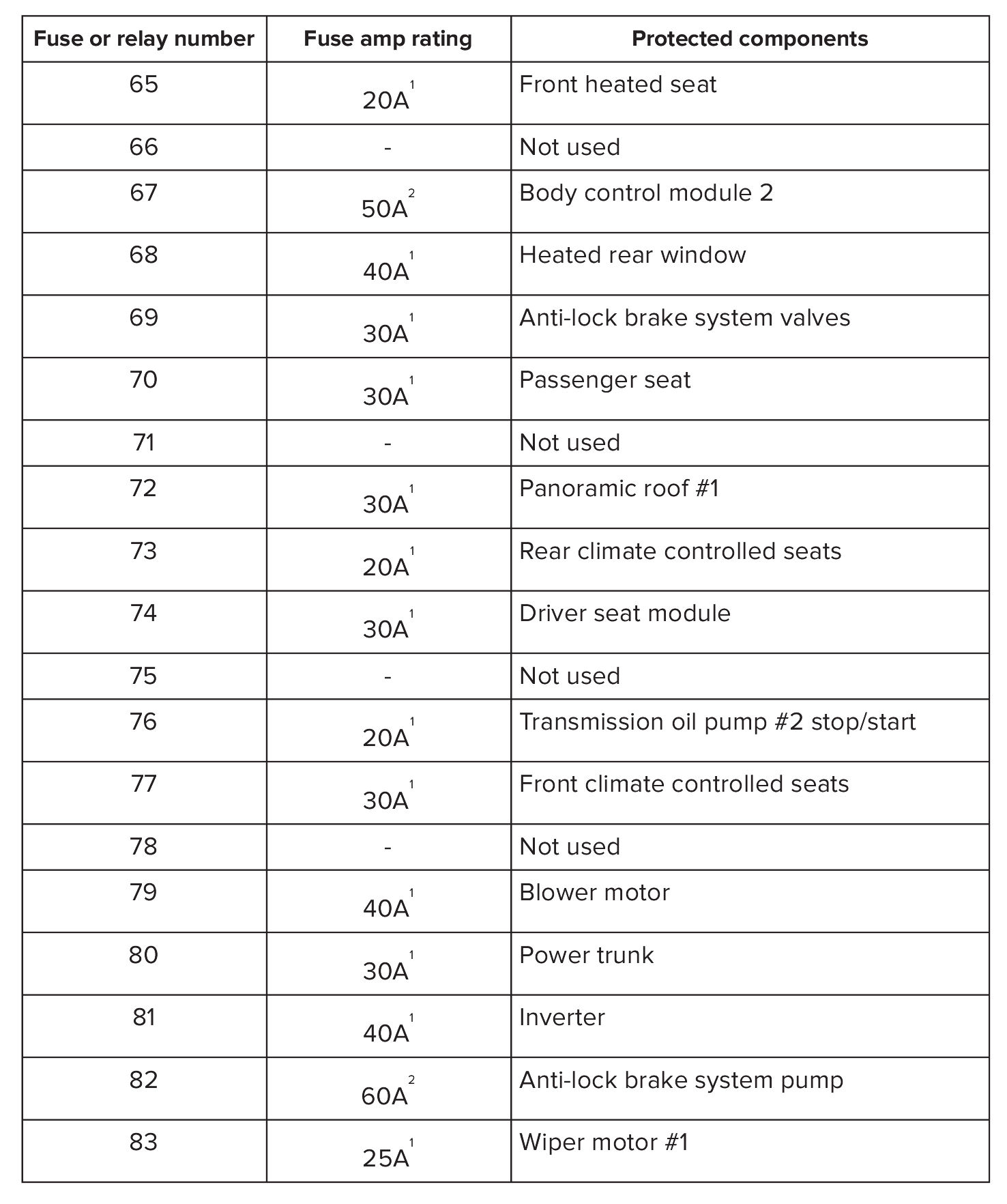
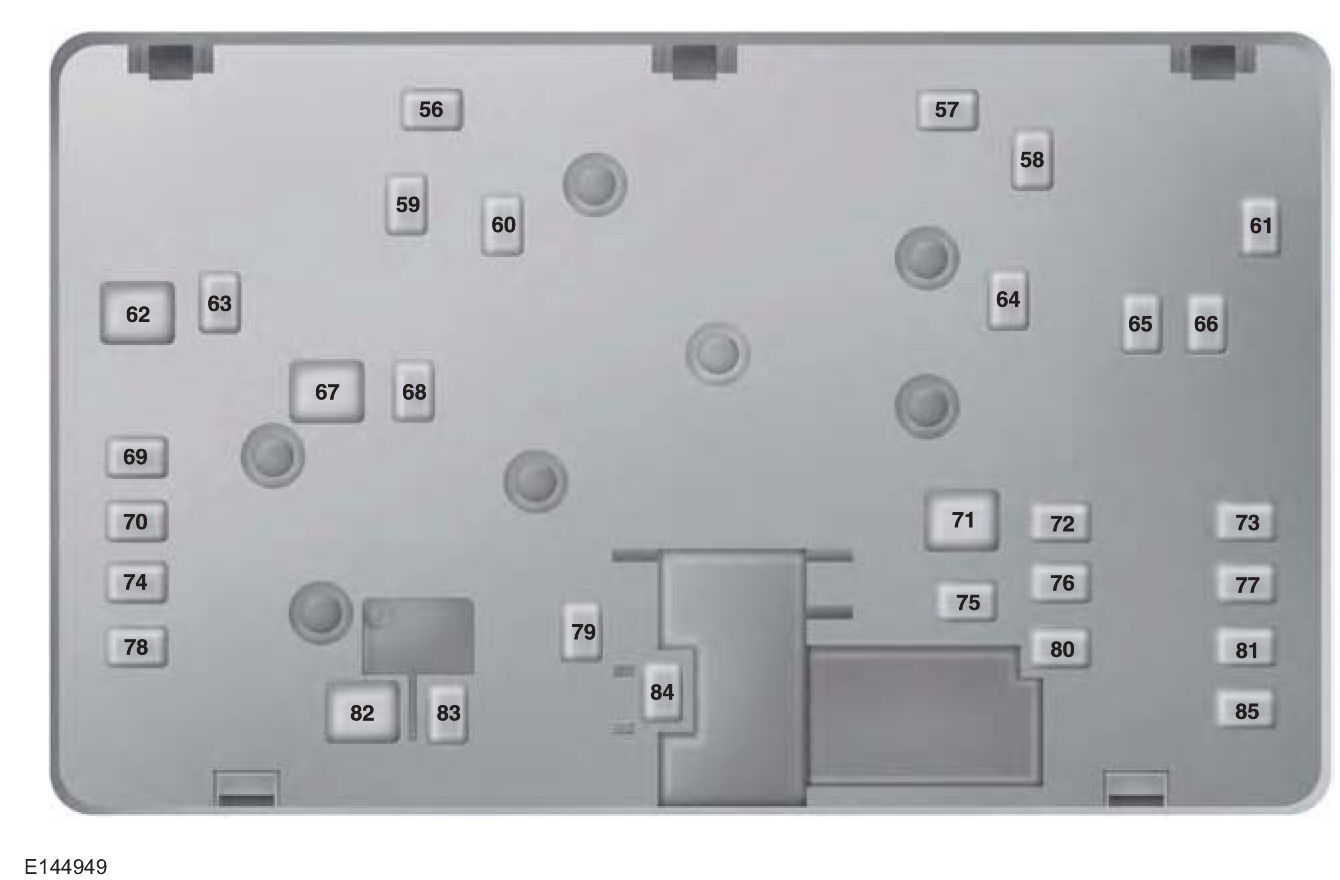
Check out the diagrams (Below). Please let us know what happens.
Was this
answer
helpful?
Yes
No
+1
Tuesday, November 26th, 2019 AT 12:01 PM

Please login or register to post a reply.

Sponsored links