Fuel Pump not working?

Tiny
JBBF250
  • MEMBER
  • 2018 FORD F-250
  • 6.2L
  • V8
  • 4WD
  • AUTOMATIC
  • 138,000 MILES
The truck wouldn’t start after a long highway drive. The tow truck driver used 2 cans of starting fluid to get the truck to start. Got home and next morning it would crank and no start. Replaced fuel pump with Motorcraft replacement. Connections at pump are connected. Removed fuel lines, have no fuel out of either line. Replaced fuel pump control module with parts store replacement. Still didn’t start. Checked Voltage at connector for FPCM. Found only 6.8 on the YW/VT wire if I remember wire color correctly.

Do these trucks need to have fuel pumps “activated” also should I have better voltage at FPCM with key in run position?

Replaced pump due to crank no start. Truck still won’t crank. Replaced FPCM. Still no start. Checked voltage at connector to FPCM found to have only 6.8 V when key is in run position. Need help with further diag.

Thanks,
Jacob
Wednesday, December 13th, 2023 AT 8:36 AM

11 Replies

Tiny
AL514
  • MECHANIC
  • 4,118 POSTS
Hello, yes the fuel pump control module should have a 12-volt power feed, but also a control wire from the PCM which is going to be a pulse width modulated signal, which is a square wave on/off signal, so you may only read around 6 volts with a multimeter because the meter will only be able to average out the voltage reading. There is also a wire that the PCM monitors the fuel pump control module on, the OEM diagrams are showing a violet/green wire as the 12-volt feed from the fuel pump relay, a brown/white wire which is the PCM monitoring wire, a yellow/orange wire which is the PCM control wire to the FPCM. The outputs to the actual fuel pump are yellow/grey (output- fppwr) and white/brown(return-fprtn) and those 2 output and return wires will be shielded by a black/white ground going to the FPCM. I'll post this OEM diagram for you. If this FPCM is located under the truck near the spare tire like they usually are, I would also check the connector very well for any corrosion inside, it's the worst place to put a control module. It looks like a 6-wire connector, is that what you have?
And this looks to be a high-pressure fuel system, do you have direct injection with a high-pressure fuel pump with steel lines in the engine compartment?
Was this
answer
helpful?
Yes
No
Wednesday, December 13th, 2023 AT 12:12 PM
Tiny
JBBF250
  • MEMBER
  • 2 POSTS
Yes, it’s the 8-pin plug with 6 wires going to it. If you could post that diagram that would be awesome. Also, I got the truck to start. Checked wiring from fuse box to FPCM. Re-installed fuse and had 10-12 Volta at plug, and it started. Went to parts house and bought new relays and fuses just to rule them out. When you pull fuel pump fuse the relay has a delayed click to it. If you click a few times the truck will start.

Thank you for the response,
Jacob
Was this
answer
helpful?
Yes
No
Wednesday, December 13th, 2023 AT 12:20 PM
Tiny
AL514
  • MECHANIC
  • 4,118 POSTS
Okay, glad you got it started. This is the OEM diagram for the FPCM and the PCM, the wires labelled FPM (Fuel Pump Monitor) and FPC (Fuel Pump Control) are going to be those pulse width modulated signals, VPWR is the 12-volt feed from the relay which sounds like it's more of the issue you're experiencing. But verify the Ground wire is good and there is no green corrosion where it attaches to the frame, I would also check any other Grounds from the frame to the body, those are sometimes the braided type, and can look okay, but still have corrosion which will cause intermittent issues with starting. I like to see those braided types replaced with a solid high gauge ground strap instead of those braided types.
Was this
answer
helpful?
Yes
No
+2
Wednesday, December 13th, 2023 AT 12:30 PM
Tiny
AL514
  • MECHANIC
  • 4,118 POSTS
If the voltage at the plug was down to 10-volts, that's no good, you need a solid 12-volts there. Modules never act right with a low voltage situation.
Was this
answer
helpful?
Yes
No
+1
Wednesday, December 13th, 2023 AT 12:33 PM
Tiny
JBBF250
  • MEMBER
  • 2 POSTS
Okay, I’ll definitely check into them. Thanks for sending that, you’re awesome. Also Thanks for the help.
Was this
answer
helpful?
Yes
No
Wednesday, December 13th, 2023 AT 12:33 PM
Tiny
AL514
  • MECHANIC
  • 4,118 POSTS
Glad to help, hope all goes well.
Was this
answer
helpful?
Yes
No
+1
Wednesday, December 13th, 2023 AT 12:41 PM
Tiny
JBBF250
  • MEMBER
  • 2 POSTS
So, I’ve narrowed it down to that relay mentioned in the schematic you posted. When the truck doesn’t want to start, I can pull the 30 Amp relay for fuel pump (75) and let it click the relay a few times with key in run position and truck will start just fine. Is that relay built into the fuse box or am I just overlooking it?

Thanks
Was this
answer
helpful?
Yes
No
Wednesday, December 13th, 2023 AT 5:35 PM
Tiny
AL514
  • MECHANIC
  • 4,118 POSTS
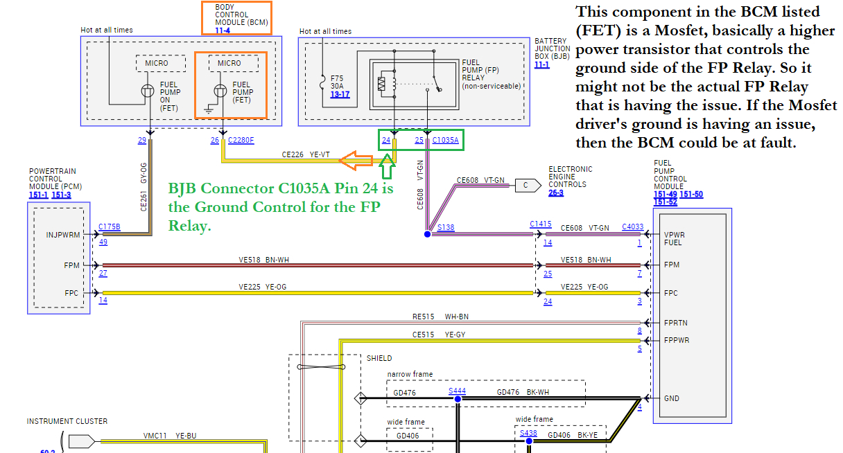
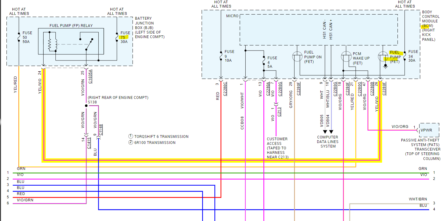
Yeah, apparently, it's not a serviceable component. Which is a really bad design. Service info states its 0.5hr to replace it but I can't see how that is possible. I would check with the dealership and see if that's really the case. If the entire Battery Junction box (BJB) needs to be replaced for one relay, I'd try taking it apart and check for a broken or cracked solder joint inside the BJB. When it comes to situations or modules like this, I'll always take them apart and try to fix myself. But if you look also at the control for the FP Relay, it's a Ground side (N-Channel) Mosfet chip inside the BCM. A Mosfet is basically a high-power transistor. I would check this circuit before replacing the BJB.

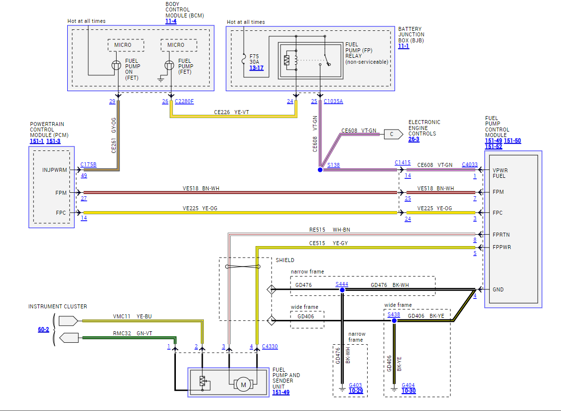
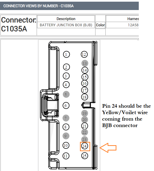
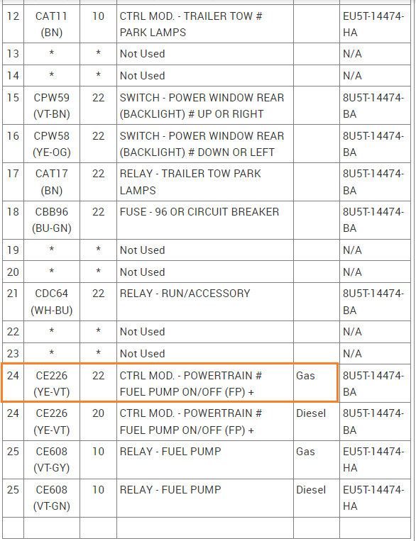
The yellow/violet colored wire (pin 24) from the BJB connector C1035A is the wire that should be grounded for the relay to turn on. If there is any voltage drop (high resistance) on this wire through the BCM, that is limiting current flow, that might be the problem. And not the FP relay.

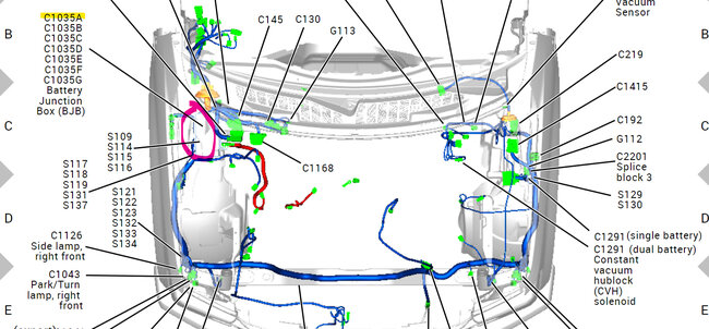
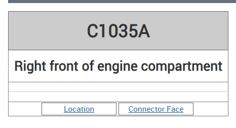
I would find connector C1035A, it's probably located on the bottom of the BJB, there is one other connector that looks the same, but its missing pins 21-24. So, you'll have to ID the connector by its wiring colors and pin locations.
With the connector still plugged in, Back probe pin 24 and with a multimeter on DC volts, measure from pin 24 and battery negative while the fault is occurring.
When the BCM is supposed to be Grounding the FP Relay you should read close to 0 volts, If the BCM is not able to fully ground the relay, you'll read some voltage drop on that wire to battery negative.

Since Fuse 75 is hot at all times you will read battery voltage on pin 24 until you turn the key On. Voltage will be coming through the FP Relay until the BCM pulls that control circuit to ground. Then it will read 0 volts.

I just don't want to see you replace the BJB and the fault still occur. Technically you could ground that pin 24 wire and the FP should kick right on, because that's all the BCM does with that Mosfet, it just makes a path to ground through it. But check for voltage drop first, see if there is any when the relay is not turning on the pump.
I added the aftermarket diagram last just to simplify the circuit, if you have any questions before the test, just let me know.

Set the multimeter on a lower DC voltage setting or auto if it has it. It may only be a couple volts of voltage drop, but may be enough to limit current flow, relays don't take much current to turn on, but I've seen mosfets burn out many times.

One other thing, since Fuse 75 feeds both sides of the FP relay, you aren't hearing the FP Relay click, it can't be because there's no power to it, you're probably hearing the PCM power relay click. If you look on that OEM diagram, with Fuse 75 out, there's no power to that FP relay at all. So, something else is going on.
Was this
answer
helpful?
Yes
No
+1
Wednesday, December 13th, 2023 AT 6:57 PM
Tiny
JBBF250
  • MEMBER
  • 2 POSTS
Okay, will do but the truck hasn’t acted up anymore in last 3-4 hours and every hour or 15 minutes I’d crank it and it would fire right up. I’ll still check it aa what I’ve done is just a Band-Aid fix for the time being. Again, thank you so much for your time for putting all this together and I will let you know how the test goes when I get time again. Thanks again.
Was this
answer
helpful?
Yes
No
Wednesday, December 13th, 2023 AT 7:10 PM
Tiny
KEN L
  • MASTER CERTIFIED MECHANIC
  • 42,940 POSTS
AL514 is one of our best! Please let us know what happens.
Was this
answer
helpful?
Yes
No
Thursday, December 14th, 2023 AT 12:19 PM
Tiny
AL514
  • MECHANIC
  • 4,118 POSTS
Let it sit overnight, if it's an issue on one of the circuit boards, its most likely going to be a thermal hot/cold type of fault.
Was this
answer
helpful?
Yes
No
Thursday, December 14th, 2023 AT 1:23 PM

Please login or register to post a reply.

Sponsored links