Fuel pump location and removal

Tiny
TRINA BURNS
  • MEMBER
  • 1992 OLDSMOBILE 98
  • 3.8L
  • 6 CYL
  • 2WD
  • AUTOMATIC
  • 125 MILES
I can't figure out if there is an easier way to get to the fuel pump than dropping the gas tank. Also, where is the fuel pump located, in the gas tank or somewhere else?
Tuesday, April 2nd, 2019 AT 5:55 AM

36 Replies

Tiny
ASEMASTER6371
  • MECHANIC
  • 52,797 POSTS
Good morning,

The fuel tank must be dropped and the pump is located in the tank.

Roy
Was this
answer
helpful?
Yes
No
+1
Tuesday, April 2nd, 2019 AT 6:17 AM
Tiny
TRINA BURNS
  • MEMBER
  • 30 POSTS
Thank you so much! You've been so helpful! Have a good day!
Was this
answer
helpful?
Yes
No
Tuesday, April 2nd, 2019 AT 10:10 AM
Tiny
ASEMASTER6371
  • MECHANIC
  • 52,797 POSTS
You are welcome.

Always glad to help.

Roy
Was this
answer
helpful?
Yes
No
+1
Tuesday, April 2nd, 2019 AT 10:11 AM
Tiny
TRINA BURNS
  • MEMBER
  • 30 POSTS
Okay, so the fuel pump and the fuel regulator has been changed. It ran great for a little over an hour, but quit again! I used a code reader, and after reading the codes, this is what I think is wrong with it, but of course, I could be wrong! Electronic spark timing is open or shorted to ground during engine run, Direct ignition system fault-bypass circuit open or shorted to ground during engine run, or ignition system fault-loss of 1X Reference Pulse signal. What do you think, and if this is it, how can I fix it?
Was this
answer
helpful?
Yes
No
Sunday, April 7th, 2019 AT 7:30 AM
Tiny
ASEMASTER6371
  • MECHANIC
  • 52,797 POSTS
Got it.

Lets start with the code you read. Can I have the code number?

Roy
Was this
answer
helpful?
Yes
No
+1
Sunday, April 7th, 2019 AT 7:35 AM
Tiny
TRINA BURNS
  • MEMBER
  • 30 POSTS
Codes 21, 34 41 58 and 65. I forgot to say this, but after changing the fuel pump, it ran like a new one! And then all of a sudden, just quit working!
Was this
answer
helpful?
Yes
No
Sunday, April 7th, 2019 AT 7:57 AM
Tiny
TRINA BURNS
  • MEMBER
  • 30 POSTS
It was the whole reason we started working on it to start with-going down the road and when the engine heated up, it would just shut off going down the road! It would crank back when it had time to cool off. Interesting thing to me though was that no warning lights came on.
Was this
answer
helpful?
Yes
No
Sunday, April 7th, 2019 AT 8:00 AM
Tiny
ASEMASTER6371
  • MECHANIC
  • 52,797 POSTS
Got it.

You will need a scan tool that can read live information to determine these failures.

21
CIRCUIT DESCRIPTION:
The Throttle Position Sensor (TPS) provides a voltage signal that changes relative to throttle blade angle. Signal voltage will vary from about 0.4 at idle to about 5 volts at wide open throttle. The TPS signal is one of the most important inputs used by the PCM for fuel control and for most of the PCM control outputs.

Code 21 will set if:

TPS voltage is greater than 4.8 volts at any time.

OR

Engine is running and air flow is less than 15 gm/sec.
TPS signal voltage is greater than 0.80 volts.
Code 34 not present.
All conditions met for 5 seconds

TEST DESCRIPTION
Numbers below refer to circled numbers on diagnostic chart.
1. With closed throttle, ignition "ON, " or at idle, voltage at BB10 should be 0.33-0.46 volt. If not adjust TPS. See ADJUSTMENTS.
2. When the TPS sensor is disconnected, the TPS voltage will go low and a Code 22 will set, indicating the PCM and wiring are OK.
3. Probing CKT 452 with a test light checks the sensor ground. A faulty sensor ground circuit will cause a Code 21.

NOTE: If a Code 21 is set, the PCM will not allow 4th gear or TCC operation.

DIAGNOSTIC AIDS:
Scan tool reads throttle position in volts. With closed throttle, ignition "ON" or at idle, voltage should be 0.33-0.46 volts. If not adjust TPS. See ADJUSTMENTS.
Also some "Scan" tools will read throttle angle as a percentage. 0% = closed throttle, 100% = WOT. An open in CKT 452 will result in a Codes 15 and 21.

If circuit 417 is open or grounded when the vehicle engine is started, a high idle may result

Check For:

Poor Connection or Damaged Harness Inspect PCM harness connectors for backed out terminal "BB10, " improper mating, broken locks, improperly formed or damaged terminals, poor terminal to wire connection, and damaged harness.

Intermittent Test. If connections and harness check OK, monitor TPS voltage while moving related connectors and wiring harness. If the failure is induced, the display will change. This may help to isolate the location of the malfunction

TPS Scaling. Observe TPS voltage display while depressing accelerator pedal with engine stopped and ignition "ON." Display should vary from closed throttle TPS voltage (0.33 - 0.46) when throttle was closed, to over 4.0 volts when throttle is wide open. Typically, accelerator pedal fully depressed should yield approx. 4.1 - 4.2 volts from the sensor. If voltage is greater than 4.8 volts at any time while operating throttle with accelerator pedal, replace the TPS.

34

CIRCUIT DESCRIPTION:
The mass air flow (MAF) sensor measures the flow of air which passes through it in a given time. The PCM uses this information to monitor the operating condition of the engine for fuel delivery calculations. A large quantity of air movement indicates acceleration, while a small quantity indicates deceleration or idle. The MAF sensor produces a frequency signal which cannot be easily measured. The sensor can be diagnosed using the procedures on this chart.

Code 34 will set when of the following conditions exists:

Engine running.
No MAF sensor signal for over 4 seconds.

TEST DESCRIPTION
Numbers below refer to circled numbers on the diagnostic chart.
1. This step checks to see if PCM recognizes a problem.
2. A voltage reading at sensor harness connector terminal "A" of less than 4 or over 6 volts indicates a fault in CKT 492 or poor connection.
3. Verifies that both ignition voltage and a good ground circuit are available.

DIAGNOSTIC AIDS:
An intermittent may be caused by a poor connection, mis-routed harness, rubbed through wire insulation, or a wire broken inside the insulation. Check for:

Poor connection at PCM pin "BD14". Inspect harness connectors for backed out terminals, improper mating, broken locks, improperly formed or damaged terminals, and poor terminal to wire connection.
Mis-routed Harness - Inspect MAF sensor harness to insure that it is not too close to high voltage wires, such as spark plug leads.
Damaged Harness - Inspect harness for damage, If harness appears OK, "Scan" while moving related connectors and wiring harness. A change in display would indicate the intermittent fault location.
Plugged Air Intake Filter - A WOT acceleration from a stop should cause the MAF reading on the "Scan tool to range from about 4.7 at idle to 100 or greater at the time of the 1-2 shift. If not, check for restriction.
Was this
answer
helpful?
Yes
No
+1
Sunday, April 7th, 2019 AT 8:03 AM
Tiny
ASEMASTER6371
  • MECHANIC
  • 52,797 POSTS
41

CIRCUIT DESCRIPTION:
During cranking, the ignition module monitors the dual crank sensor sync signal. The sync signal is used to determine the correct cylinder pair to spark first. After the sync signal has been processed by the ignition module it sends a fuel control reference pulse to the PCM. When the PCM receives this pulse it will command all six injectors to open for a (priming) shot of fuel in all cylinders. After the priming, the injectors are left "OFF" for the next six fuel control reference pulses (two crankshaft revolutions) from the ignition module. This allows each cylinder a chance to use the fuel from the (priming) shot. During this waiting period, a cam pulse will have been received by the PCM. Now the PCM begins to operate the injectors sequentially, based on true camshaft position. However, if the cam signal is not present at start-up a code 41 will be set and the PCM will start sequential fuel delivery in any old random pattern. The engine has a 1 in 6 chance that fuel delivery is correct.

Code 41 sets when the following condition exists:

Cam sensor signal not received by by the PCM for 5 seconds while engine is running.

TEST DESCRIPTION

Code 41 Diagnostic Chart (Type I Ignition)
imageOpen In New TabZoom/Print

Numbers below refer to circled numbers on the diagnostic chart.
1. This step verifies proper operation of CKTs 633, 644, and 645.
2. Step validates the integrity of CKT 630 from C3I module to PCM.
3. If the camshaft gear magnet is interfacing with the cam sensor, the voltage reading will be zero. Bumping engine with the starter will rotate the magnet away from the sensor and the voltage reading should change to greater than 8 volts.
4. If the voltage reading of "BA12" is constantly varying and connection to the PCM is good, the PCM is faulty.

DIAGNOSTIC AIDS:

An intermittent may be caused by a poor connection, rubbed through wire insulation or a wire broken inside the insulation. Check For:

Poor Connection or a damaged Harness inspect PCM harness connectors for backed out terminal "BA12, " improper mating, broken locks, improperly formed or damaged terminals, poor terminal to wire connection and damaged harness.
Intermittent Test If connections and harness check OK, monitor a digital voltmeter connected from PCM terminal "BA12" to ground while moving related connectors and wiring harness. If the failure is induced, the voltage reading will change. This may help to isolate the location of the malfunction.

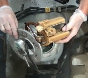
58 This may be the one. It is for the ignition lock cylinder. If the wires are broken, it will not run.

CIRCUIT DESCRIPTION:

When the ignition is turned "ON", the PASS-key(registered trademark) decoder "reads" the key resistor pellet. If the proper resistance is recognized by the PASS-key(registered trademark) decoder module, it sends a PWM fuel enable signal via CKT 229 to the PCM. The PCM looks for this signal during cranking and allows fuel delivery by enabling the injectors when the signal is recognized. If the fuel enable signal is lost while the engine is running, the PCM will store code 58 and the vehicle will run normally. As long as code 58 is stored, the PCM will ignore any absence of the fuel enable signal and the car will start and run as long as the problem is isolated to the fuel enable circuit only.

TEST DESCRIPTION

Code 58 Diagnostic Chart
imageOpen In New TabZoom/Print

Numbers below refer to circled numbers on the diagnostic chart.

1. If the vehicle will not crank with code 58 stored, the problem affects the entire PASS-key(registered trademark) system and is not isolated to the fuel enable circuit.

2. The PCM supplies 5 volts to CKT 229 which the PASS-key(registered trademark) decoder module pulses to ground when the correct key is recognized. This test ensures that the PCM is supplying 5 volts and CKT 229 is not open or shorted to ground.

3. Checks the PWM signal from the PASS-key(registered trademark) module. Since the 5 volts supplied by the PCM is being pulsed to ground, voltage on CKT 229 should measure around 2.5 volts.

4. Checks for a faulty PCM or intermittent condition by clearing code 58. Since the PCM ignores the absence of a fuel enable signal only when 58 is stored, the vehicle should not start if the problem is present and code 58 is not.

DIAGNOSTIC AIDS:
An intermittent Code 58 and possible "no-start" condition could be caused by:

Loss of power or ground to PASS-key(registered trademark) decoder module. A loose ground or poor ignition or battery connection.

Dirty, damaged, or loose connections or damaged harness. Check for any damage to the harness which could cause an intermittent open or short to ground, backed out terminals at the PCM and PASS-key(registered trademark) decoder module connectors, broken locks, improperly formed or damaged terminals.

65

CIRCUIT DESCRIPTION:
The PCM supplies a 5v reference voltage to the cruise control Servo Position Sensor (SPS), through circuit 398. Depending on the actual servo position, the signal on CKT 399 will vary indicating the servo position to the PCM. The PCM uses this information to control the servo position when cruise is engaged.

Code 65 will set if:
CKT 398 is open, grounded or shorted to voltage.
CKT 399 is opened.

NOTE: Code 65 does not turn on the "SES" light.

DIAGNOSTIC AIDS:
An intermittent may be caused by a poor connection, worn through wire insulation, or a wire broken inside the insulation.
Poor connection or damaged harness. Inspect harness connectors for backed out terminals, improper mating, broken locks, bad terminals, poor terminal to wire connections, and damaged harness.

Roy
Was this
answer
helpful?
Yes
No
+1
Sunday, April 7th, 2019 AT 8:06 AM
Tiny
TRINA BURNS
  • MEMBER
  • 30 POSTS
It was the whole reason we started working on it to start with-going down the road and when the engine heated up, it would just die going down the road! It would crank back when it had time to cool off! Interesting thing to me though was that no warning lights came on!
Was this
answer
helpful?
Yes
No
Sunday, April 7th, 2019 AT 8:14 AM
Tiny
ASEMASTER6371
  • MECHANIC
  • 52,797 POSTS
I see you responded but nothing came through.

Roy
Was this
answer
helpful?
Yes
No
+1
Sunday, April 7th, 2019 AT 8:15 AM
Tiny
TRINA BURNS
  • MEMBER
  • 30 POSTS
The car cranks and runs for about a little over an hour, then quits. I have checked to see if it was getting any fire, and it is not. I have replaced the cam and crank sensor, and will be replacing the position sensor today.
Was this
answer
helpful?
Yes
No
Sunday, April 7th, 2019 AT 8:29 AM
Tiny
ASEMASTER6371
  • MECHANIC
  • 52,797 POSTS
That sensor has no effect on spark. The ignition module and the coils control spark.

Roy
Was this
answer
helpful?
Yes
No
+1
Sunday, April 7th, 2019 AT 8:31 AM
Tiny
TRINA BURNS
  • MEMBER
  • 30 POSTS
What would you do with this problem?
Was this
answer
helpful?
Yes
No
Sunday, April 7th, 2019 AT 8:34 AM
Tiny
ASEMASTER6371
  • MECHANIC
  • 52,797 POSTS
This needs to be checked by someone who is familiar with the way the ignition system works. At this point I am leaning toward the ignition module.

Roy
Was this
answer
helpful?
Yes
No
+1
Sunday, April 7th, 2019 AT 8:45 AM
Tiny
TRINA BURNS
  • MEMBER
  • 30 POSTS
Thank you so much! Have a good day!
Was this
answer
helpful?
Yes
No
Sunday, April 7th, 2019 AT 8:54 AM
Tiny
ASEMASTER6371
  • MECHANIC
  • 52,797 POSTS
You are welcome.

Always glad to help.

Roy
Was this
answer
helpful?
Yes
No
+1
Sunday, April 7th, 2019 AT 8:55 AM
Tiny
TRINA BURNS
  • MEMBER
  • 30 POSTS
The ignition module was changed today. Interestingly enough, it had heat bubbles on it. It was replaced, but problem is still there. Any more thoughts?
Was this
answer
helpful?
Yes
No
Sunday, April 7th, 2019 AT 1:38 PM
Tiny
TRINA BURNS
  • MEMBER
  • 30 POSTS
The ignition module was changed today-interestingly enough, it had heat bubbles on it. It was replaced, but problem is still there. Any more thoughts?
Was this
answer
helpful?
Yes
No
Sunday, April 7th, 2019 AT 1:38 PM
Tiny
ASEMASTER6371
  • MECHANIC
  • 52,797 POSTS
Still no spark when it stalls?

Did you replace the coils as well?

Roy
Was this
answer
helpful?
Yes
No
+1
Sunday, April 7th, 2019 AT 2:48 PM

Please login or register to post a reply.

Sponsored links