Welcome back. The vehicle still has a regulator, but it is different than the old ones. The fuel system is a return-less on-demand design. The fuel pressure regulator is a part of the fuel tank module which eliminates the need for a return pipe from the engine. I have to be honest, I do not know why the pressure was low and now normal other than there is a problem with the pump or the regulator. That is the only thing (other than a plugged fuel filter) that is going to cause the issue.
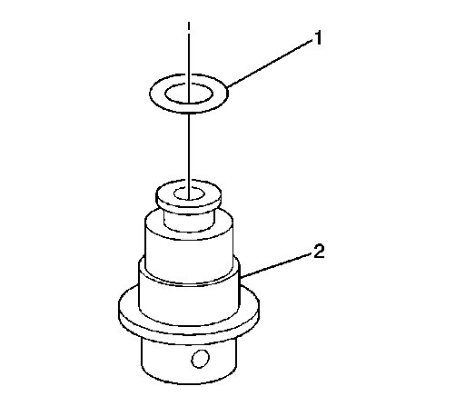
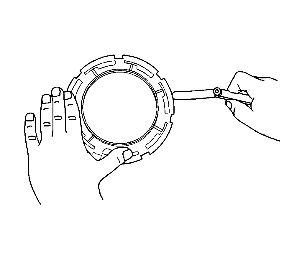
If you decide to remove the pump, here are the directions. Picture 1 is what the regulator looks like. All remaining pictures correlate with these directions.
______________________________
FUEL TANK MODULE REPLACEMENT
Fuel Tank Module Replacement
Tools Required
J 45722 Fuel Sender Lock Ring Tool
Removal Procedure
Notice: Clean all of the following areas before performing any disconnections in order to avoid possible contamination in the system:
* The fuel pipe connections
* The hose connections
* The areas surrounding the connections
1. Remove the fuel tank. Refer to Fuel Tank Replacement (See: Fuel Tank > Removal and Replacement) .
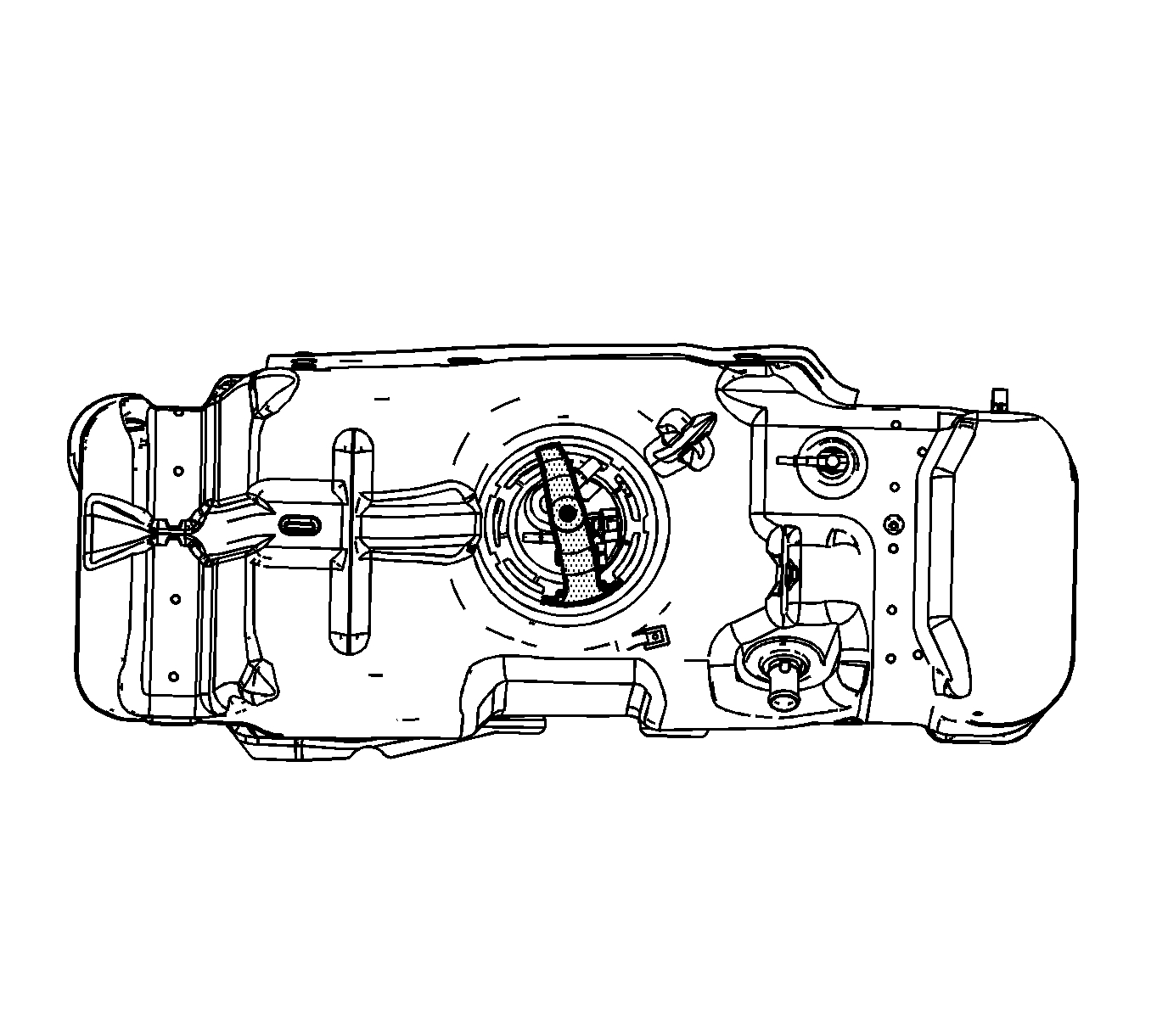
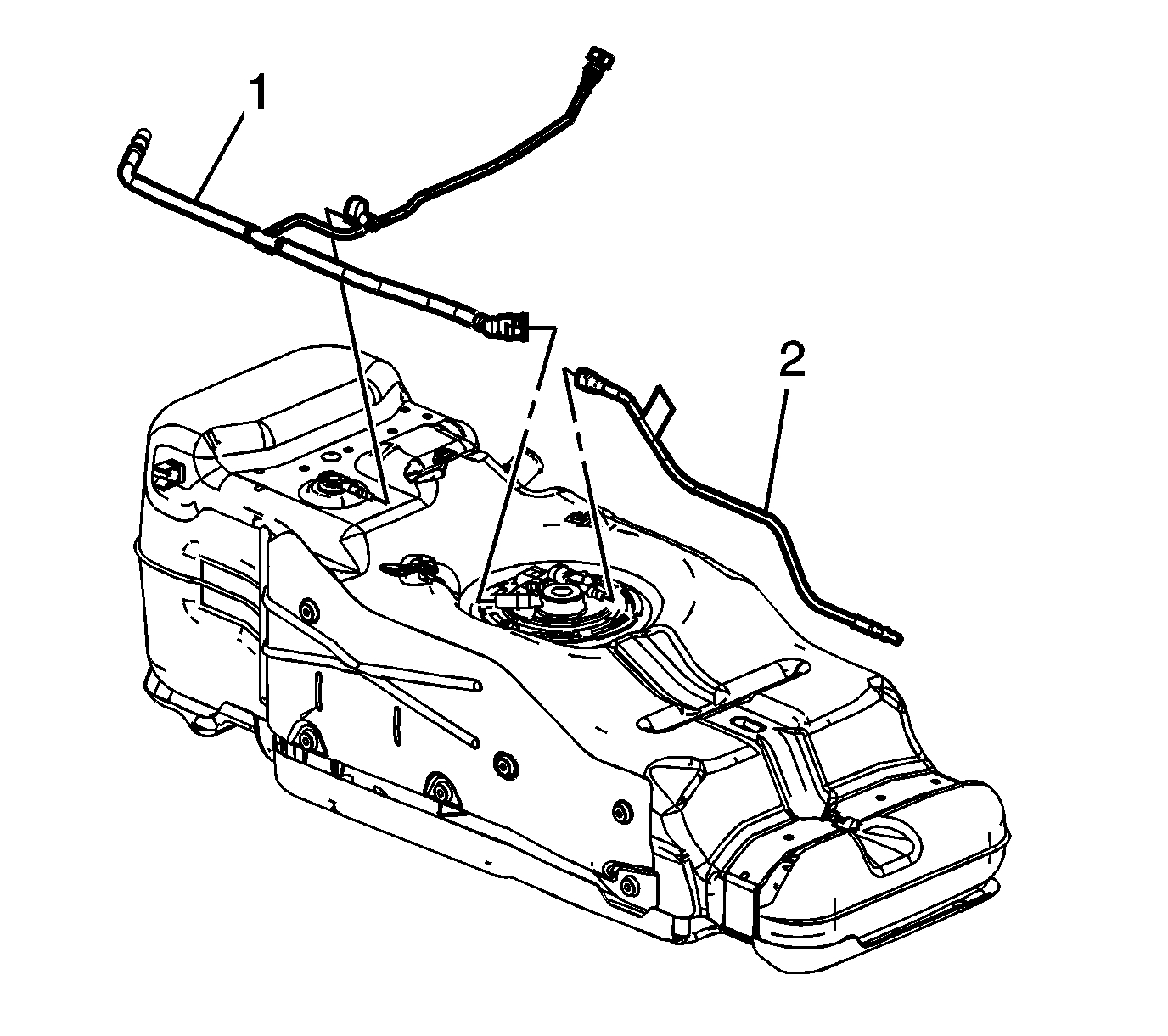
2. Disconnect the evaporative emission (EVAP) line (1) quick connect fittings from the module and the vent valve. Refer to Plastic Collar Quick Connect Fitting Service (See: Fuel Line Coupler > Removal and Replacement > Plastic Collar Quick Connect Fitting Service) .
3. Remove the EVAP line from the clip on the side of the fuel tank.
4. Disengage the EVAP line from the retaining features molded into the fuel tank and remove the EVAP line.
5. Disconnect the fuel feed line (2) quick connect fitting from the module. Refer to Plastic Collar Quick Connect Fitting Service (See: Fuel Line Coupler > Removal and Replacement > Plastic Collar Quick Connect Fitting Service) .
6. Disengage the fuel feed line from the retaining feature molded into the fuel tank and remove the fuel line.
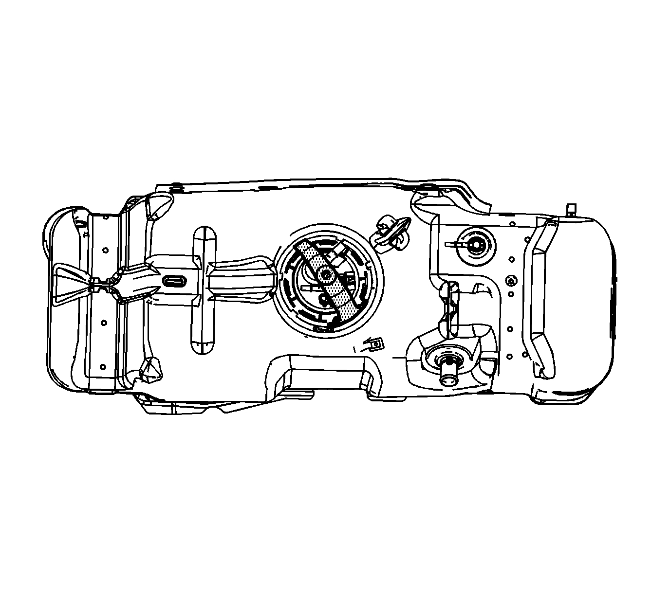
7. Install the J 45722 to the fuel pump module lock ring.
Notice: Avoid damaging the lock ring. Use only J-45722 to prevent damage to the lock ring.
Notice: Do Not handle the fuel sender assembly by the fuel pipes. The amount of leverage generated by handling the fuel pipes could damage the joints.
Important: Do NOT us impact tools. Significant force will be required to release the lock ring. The use of a hammer and screwdriver is not recommended. Secure the fuel tank in order to prevent fuel tank rotation.
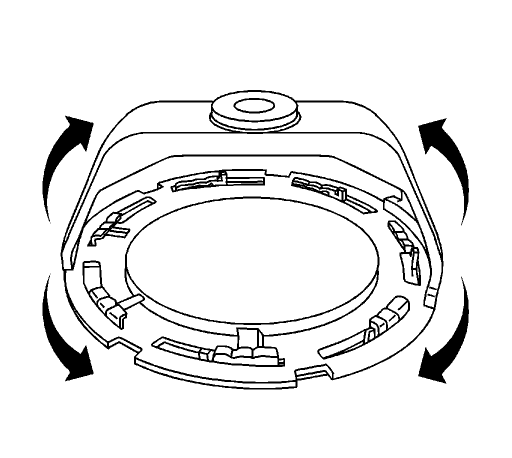
8. Using the J 45722 and a long breaker-bar, rotate the lock ring in a counterclockwise direction in order to unlock the lock ring.
9. Remove the J 45722 from the fuel pump module lock ring.
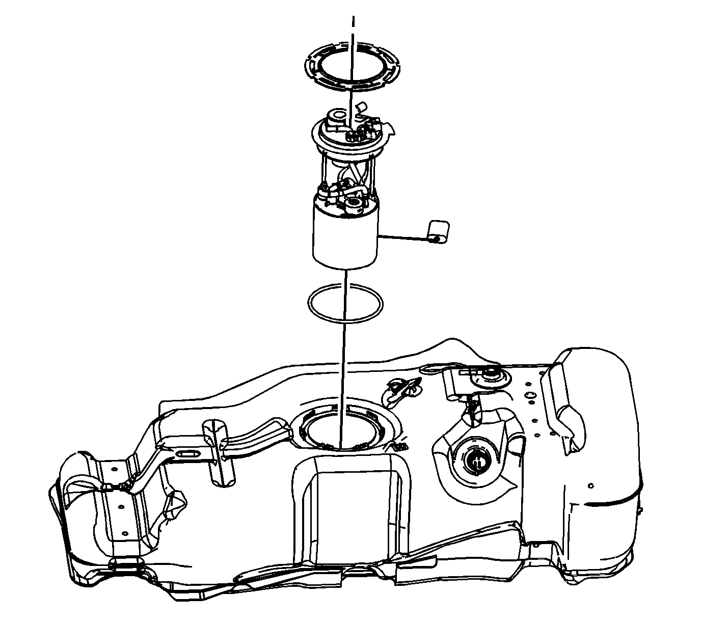
10. Raise the fuel pump module up from the fuel tank. Tilt the module in order to allow the fuel level sensor arm and float to clear the module opening.
11. Remove the fuel pump module.
12. Remove and discard the fuel pump module seal.
Caution: Drain the fuel from the fuel sender assembly into an approved container in order to reduce the risk of fire and personal injury. Never store the fuel in an open container.
13. Clean the fuel pump module sealing surface.
Important: Some lock rings were manufactured with DO NOT REUSE stamped into them. These lock rings may be reused if they are not damaged or warped.
Important: Inspect the lock ring for damage due to improper removal or installation procedures. If damage is found, install a NEW lock ring.
Important: Check the lock ring for flatness.
14. Place the lock ring on a flat surface. Measure the clearance between the lock ring and the flat surface using a feeler gage at 7 points.
15. If warpage is less than 0.41 mm (0.016 in), the lock ring does not require replacement.
16. If warpage is greater than 0.14 mm (0.016 in), the lock ring must be replaced.
Installation Procedure
Caution: In order to reduce the risk of fire and personal injury that may result from a fuel leak, always replace the fuel sender gasket when reinstalling the fuel sender assembly.
1. Clean any contamination from the male pipe ends of the fuel pump module.
2. Place a NEW fuel tank module seal onto the fuel tank.
3. Insert the fuel pump module into the fuel tank allowing the sensor arm and float to clear module opening.
4. Lower the module down into the fuel tank.
5. Press the fuel tank module downward, aligning the tang with the notch in the fuel tank.
6. Install the fuel pump module lock ring onto the fuel tank.
7. Install the J 45722 to the fuel pump module lock ring.
Important: Always replace the fuel module seal when installing the fuel pump module. Replace the lock ring if necessary. Do not apply any type of lubrication in the seal groove.
Ensure the lock ring is installed with the correct side facing upward. A correctly installed lock ring will only turn in a clockwise direction.
8. Using the J 45722 and a long breaker-bar, rotate the lock ring in a clockwise direction on order to lock the lock ring.
9. Remove the J 45722 from the fuel pump module lock ring
10. Connect the fuel feed line (2) quick connect fitting to the module. Refer to Plastic Collar Quick Connect Fitting Service (See: Fuel Line Coupler > Removal and Replacement > Plastic Collar Quick Connect Fitting Service) .
11. Engage the fuel feed line to the retaining feature molded into the fuel tank.
12. Connect the EVAP line (1) quick connect fittings to the module and the vent valve. Refer to Plastic Collar Quick Connect Fitting Service (See: Fuel Line Coupler > Removal and Replacement > Plastic Collar Quick Connect Fitting Service)
13. Engage the EVAP line to the retaining feature molded into the fuel tank.
14. Install the EVAP line to the clip on the side of the fuel tank.
15. Install the fuel tank. Refer to Fuel Tank Replacement (See: Fuel Tank > Removal and Replacement) .
____________________________________
Let me know if this helps or if you have other questions.
Joe
Images (Click to enlarge)
Sep 24, 2018 at 4:58 PM