Hi MARYLOU12,
There are 20 procedures to check and I have them here for you. If you are not able to perform the testing, the following should provide your mechanic with sufficient data to diagnose the fault.
SYSTEM INOPERATIVE
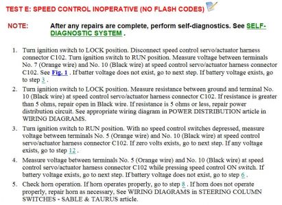
1. Check Power To Servo - Unplug harness connector from servo. Turn ignition on. Using DVOM, measure voltage between pins No. 7 and 10 of servo connector. See Fig. 1 . If battery voltage exists, go to step 4). If battery voltage does not exist, go to next step.
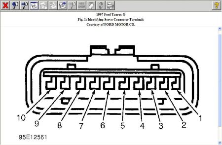
2. Check Power To Servo - Turn ignition on. Check for battery voltage between servo connector pin No. 7 and chassis ground. If battery voltage exists, go to next step. If battery voltage does not exist, check fuses and replace as necessary. If fuses are okay, repair open power circuit. If fuse repeatedly blows check circuit for short to ground and repair as necessary.
3. Check Module Ground - Measure resistance between servo connector pin No. 10 and chassis ground. If resistance is less than 5 ohms, repeat step 1). If resistance is greater than 5 ohms, repair ground circuit.
4. Check Deactivator Switch Circuit - Turn ignition on. With brake released, measure voltage between pin No. 9 at servo connector and ground. If battery voltage exists, go to step 7). If battery voltage does not exist, go to next step.
5. Check Power To Deactivator Switch - Disconnect deactivator switch harness connector. Deactivator switch is either a pressure activated switch in the brake hydraulic circuit (on or near master cylinder) or a brake pedal mounted switch in addition to stoplight switch. Check for battery voltage at specified wire. See the BRAKE/DEACTIVATOR SWITCH POWER TABLE . If battery voltage exists, go to next step. If battery voltage does not exist, check for blown fuse or open circuit. Repair as necessary.
BRAKE/DEACTIVATOR SWITCH POWER
Application ---- Wire color
Taurus Light Green/Red
6. Check Deactivator Switch-To-Servo Circuit - Measure resistance between servo connector pin No. 9 and matching wire color at deactivator switch harness connector. If resistance is less than 5 ohms, replace deactivator switch. If resistance is greater than 5 ohms, repair open circuit between deactivator switch and servo connectors.
7. Check Stoplight Switch - With brake pedal released, measure voltage on pin No. 4 at servo connector. If battery voltage exists, replace stoplight switch. If battery voltage does not exist, go to next step.
8. Check Stoplight Circuit - Measure voltage on pin No. 4 at servo connector while depressing brake pedal. If battery voltage exists, go to step 12). If battery voltage does not exist, go to next step.
9. Check Stoplight Switch Resistance - Disconnect stoplight switch. Measure resistance across stoplight switch terminals while exercising switch. If resistance is less than 5 ohms with brakes applied, go to next step. If resistance is greater than 5 ohms, with brakes applied, replace stoplight switch.
10. Check Power To Stoplight Switch - Disconnect stoplight switch harness connector. Check for battery voltage at stoplight switch. See BRAKE/DEACTIVATOR SWITCH POWER TABLE . If battery voltage exists, go to next step. If battery voltage does not exist, check for blown fuse or open circuit. Repair as necessary.
11. Check Stoplight Switch-To-Servo Circuit - Measure resistance between servo connector pin No 4 and matching color wire at stoplight switch harness connector. If resistance is less than 5 ohms, check harness connectors for corrosion or damage. Repair as necessary. If resistance is greater than 5 ohms, repair open circuit between stoplight switch and servo connectors.
12. Check For Stuck ON Switch - With no cruise control switches pressed, check voltage on pin No. 5 at servo connector. If battery voltage exists, replace cruise control switch assembly. If battery voltage does not exist, go to next step.
13. Check ON Switch Operation - While pressing cruise control ON switch, measure voltage of pin No. 5 at servo connector. If battery voltage exists, go to step 17). If battery voltage does not exist, go to next step.
14. Check For Power To Clockspring - Disable air bag system. Disconnect clockspring connector at base of steering column. Turn ignition on. Check for battery voltage on specified wire at clockspring harness connector at base of steering column. See CLOCKSPRING POWER CIRCUIT table. If battery voltage exists, go to next step. If battery voltage does not exist, replace blown fuse or repair open circuit between fuse panel and clockspring connector.
CLOCKSPRING POWER CIRCUIT
Application ---- Wire color
Taurus Yellow/Light Green
15. Check Clockspring - Disable air bag system. Disconnect clockspring connector at base of steering column. Remove drivers-side air bag module. Remove cruise control actuator switch assembly. Measure resistance of all wires between base of steering column and actuator switch connector on clockspring. If resistance is greater than 0.5 ohm on any circuit, replace clockspring. If resistance is less than 0.5 ohm on all circuits, go to next step.
16. Check Circuits From Clockspring To Servo - Disconnect servo electrical connector. Measure resistance of wire between servo terminals No. 5 and corresponding color wire at clockspring connector at base of steering column. Repeat procedure for servo connector terminal No. 6 circuit. If resistance is greater than one ohm, repair suspect wire(s). If resistance is less than one ohm, check circuits for short to ground. If circuits are okay, go to next step. If circuit(s) are open or shorted to ground, repair as necessary.
17. Check For Stuck Switch - Disconnect servo connector. Measure resistance between terminals No. 5 and 6 at servo connector. DO NOT press any cruise control switches on steering wheel. If resistance is greater than 3000 ohms, go to next step. If resistance is less than 3000 ohms, replace cruise control command switch assembly.
18. Check Switch Resistance - To check switches, measure resistance between pins No. 5 and 6 of servo connector while pressing each control button. If any resistance is not as specified, replace control switch assembly. See CONTROL SWITCH RESISTANCES table. If all resistances are as specified, go to next step.
CONTROL SWITCH RESISTANCES
Button Depressed --- Ohms
COAST 115-125
OFF 0-4
RESUME 2090-2310
SET/ACCEL 645-715
19. Check Vehicle Speed Sensor (VSS) Circuit - Test drive vehicle. If speedometer is inoperative, diagnose and repair VSS or VSS circuit as necessary. If speedometer operates properly, disconnect harness connectors from VSS and servo. Measure resistance of wire between servo pin No. 3 and same wire at VSS harness connector (pin No. 3 and anti -lock brake module harness connector on Taurus SHO). If resistance is less than 5 ohms, go to next step. If resistance is greater than 5 ohms, repair open in VSS (servo pin No. 3) circuit.
20. Check For Broken Or Binding Servo Cable - Remove servo cable from servo. Check for broken or binding cable by pulling on cable ball slug. Replace cable as necessary. If cable is okay, replace servo.
Sunday, February 1st, 2009 AT 1:42 PM