P1443 = Very small or no purge flow condition.
Here are the diagnostic procesures. They would allow you to perform test to determine what is causing the problem. I have printed the complrete procedures and not all of them are relevant and you need to check only those that are.
CIRCUIT TEST HW - EVAPORATIVE EMISSION PURGE FLOW SYSTEM
Diagnostic Aids
Perform this test when instructed during QUICK TEST or if directed by other test procedures. This test is used to diagnose the following:
"¢ Leaks in fuel tank, filler cap or vapor hoses.
"¢ Wiring harness circuits (CANP SIG, PF, PWR GND, VMV and VPWR).
"¢ Faulty Canister Purge (CANP) solenoid.
"¢ Faulty Purge Flow (PF) Sensor.
"¢ Faulty Vapor Management Valve (VMV).
"¢ Faulty carbon canister.
"¢ Faulty PCM. "¢
1) DTC P0443: Check VPWR Circuit Voltage Disconnect Canister Purge (CANP) solenoid or Vapor Management Valve (VMV) wiring harness connector. Turn ignition on. Measure voltage between VPWR terminal of CANP solenoid or VMV wiring harness connector and battery ground. If voltage is 10.5 volts or more, go to next step. If voltage is less than 10.5 volts, repair open in VPWR circuit and repeat QUICK TEST .
2) Check Component Resistance Turn ignition off. Leave CANP or VMV wiring harness connector disconnected. Measure resistance between CANP solenoid or VMV terminals. For CANP solenoid, if resistance is 30-90 ohms, go to next step. For VMV, if resistance is 30-38 ohms, go to step 4). If resistance is not as specified, replace CANP solenoid or VMV. Clear PCM memory and repeat QUICK TEST .
3) Check CANP Solenoid For Internal Short Turn ignition off. Leave wiring harness connector disconnected. Measure resistance between each solenoid terminal and CANP solenoid housing. If each resistance measurement is more than 90 ohms, CANP solenoid is okay. Go to next step. If resistance is not as specified, replace CANP solenoid. Clear PCM memory and repeat QUICK TEST .
4) Check VMV Circuit Continuity Leave ignition off and CANP or VMV wiring harness connector disconnected. Disconnect PCM wiring harness connector. Inspect pins for damage and repair as necessary. Install EEC-V Breakout Box (014-000950), leaving PCM disconnected. Measure resistance as follows:
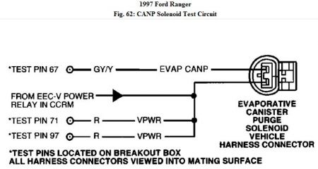
"¢ For CANP solenoid, between test pin No. 67 at breakout box and EVAP CANP terminal of CANP solenoid wiring harness connector.
"¢ For VMV, between test pin No. 56 at breakout box and VMV terminal of VMV wiring harness connector.
If resistance is less than 5 ohms, go to next step. If resistance is 5 ohms or more, repair open circuit and repeat QUICK TEST .
5) Check Circuit For Short To PWR GND Leave ignition off. Disconnect scan tester from DLC (if applicable). Measure resistance between test pin No. 67 (CANP solenoid) or 56 (VMV) and test pins No. 24 and 103. If each resistance is more than 10,000 ohms, go to step 22). If resistance is 10,000 ohms or less, repair EVAP CANP/VMV circuit short to PWR GND circuit. Clear PCM memory and repeat QUICK TEST .
6) Continuous Memory DTC P1443 This DTC can set by Idle Air Control (IAC) valve speed error during vehicle operation. If Continuous Memory DTC P1507 is also present, go to CIRCUIT TEST KE , step 30). Connect scan tester to Data Link Connector (DLC). Turn ignition on. Using scan tester, access IAC PID, TP PID and RPM PID. Turn all accessories off. Start engine and allow to idle. IAC duty cycle should be 20-45%. Observe IAC PID and RPM PID for indication of fault while shaking and bending IAC valve wiring harness and connector. A fault will be indicated by sudden increase of engine speed and decrease in IAC duty cycle. Rapidly press and release the throttle several times while looking for slow return to idle (observing the TP PID. This may indicate a sticking IAC valve. If fault is indicated, isolate and repair as necessary. If no fault is go to step 8).
7) Check Purge Flow (PF) Sensor Turn ignition off. Connect scan tester to Data Link Connector (DLC). Disconnect PF sensor wiring harness connector. Inspect connector for damage and repair if necessary. Reconnect PF sensor harness connector. Start engine and allow to idle. Using scan tester, access PF PID. If voltage fluctuates about 0.9-1.1 volts, go to step 19). If voltage fluctuates 2.2-2.6 volts, go to step 18). If voltage does not fluctuate as specified, go to next step.
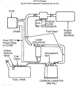
8) Visual Check Of EVAP System Check for kinked or pinched fuel vapor tubes/hoses between EVAP canister, EVAP canister purge valve and engine intake manifold. Check for cracked or smashed EVAP canister. If a fault is indicated, repair fuel vapor tubes/hoses as necessary. If EVAP canister is cracked or smashed, replace EVAP canister. If components are replaced, go to step 42. If a fault is not indicated, for CANP solenoid, go to step 11). For VMV, go to next step.
9) Check VPWR At CANP Solenoid Disconnect EVAP canister purge valve harness connector. Turn ignition on, engine off. Measure VPWR circuit voltage between CANP solenoid valve harness connector and battery negative post. Turn ignition off. If the voltage was greater than 10.5 volts, go to next step. If the voltage was not greater than 10.5 volts, repair open circuit. Reconnect any disconnected components. Reset PCM to clear DTCs and repeat QUICK TEST .
10) Check EVAP System Install EEC-V Breakout Box (014-000950), connect PCM to breakout box. Disconnect fuel vapor hose to CANP solenoid at EVAP canister. Install a vacuum gauge to open end of fuel vapor hose. Start engine and idle engine for 5 minutes. Observe the vacuum gauge. Reading must be near 0 in. Hg (0 kPa). Connect a jumper between PCM test pin 56 and PCM test pin 51 or 103, while engine is still running. Idle the engine for additional 5 to 10 minutes. Observe the vacuum gauge. Turn ignition off. If the vacuum reading changed from near 0 in. Hg (0 kPa) to 10 in. Hg (33.77 kPa) or greater with addition of jumper, remove vacuum gauge. Inspect the fuel vapor tubes/hoses between the EVAP canister and the EVAP canister purge valve and between the EVAP canister purge valve and the intake manifold for small cracks, splits or holes. Repair as necessary. Reconnect any disconnected components and go to next step. If the vacuum reading does not change from near 0 in. Hg (0 kPa) to 10 in. Hg (33.77 kPa) or greater with addition of jumper, remove vacuum gauge. Leave the fuel vapor hose from EVAP canister disconnected. For vacuum readings within 6-10 in. Hg (20.26-33.77 kPa), go to step 12). For vacuum readings less than 6 in. Hg (20.26 kPa), go to step 13).
11) Check EVAP Canister Disconnect fuel vapor hose to EVAP canister purge valve at EVAP canister. Check for contamination or blockages at all ports on EVAP canister (to the fuel tank, to the EVAP canister purge valve and to the atmosphere). If a fault indicated, repair EVAP canister. Reconnect any disconnected components. If components are replaced, go to step 42). If a fault is not indicated, go to next step.
12) Check For Vacuum Leak Between CANP Solenoid & EVAP Canister Disconnect other end of fuel vapor hose from EVAP canister at CANP solenoid. Plug open end of fuel vapor hose at EVAP canister. Install a hand vacuum pump to open end of fuel vapor hose at CANP solenoid. Apply 16 in. Hg (53 kPa) of vacuum with vacuum pump. If the vacuum pump holds the vacuum, remove plug in hose and go to next step. If the vacuum pump does not hold the vacuum, replace damaged fuel vapor hose. Reconnect any disconnected components and go to step 42).
13) Check For Hose Blockage Between CANP Solenoid & EVAP Canister Disconnect other end of fuel vapor hose from EVAP canister at EVAP canister purge valve. Install a hand vacuum pump to open end of fuel vapor hose at EVAP canister purge valve. Apply 16 in. Hg (53 kPa) of vacuum with vacuum pump. If the vacuum pump holds the vacuum, remove vacuum pump. Repair or straighten fuel vapor hose as necessary. Reconnect any disconnected components and go to step 42). If the vacuum pump does not hold vacuum, remove vacuum pump. For CANP solenoid, reconnect fuel vapor hose at EVAP canister. Leave other end of fuel vapor hose disconnected at CANP solenoid and go to step 17). For VMV, reconnect fuel vapor hose between EVAP canister and CANP solenoid and go to next step.
14) Check For Filter Contamination Or Damage To CANP Solenoid Disconnect vacuum line from input vacuum port to intake manifold on CANP solenoid. Install a hand vacuum pump to input vacuum port on EVAP canister purge valve. Apply 10-15 in. Hg (48-52 kPa) of vacuum to CANP solenoid. If the CANP solenoid holds vacuum or shows a very slow release of vacuum to atmosphere, repair CANP solenoid filter blockage or replace CANP solenoid. Reconnect any disconnected components and go to step 42). If the CANP solenoid does not hold vacuum or releases vacuum slowly to atmosphere, remove vacuum pump and go to next step.
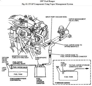
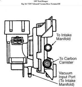
15) Check For Vacuum At VMV Ensure VMV is electrically connected. Disconnect both input port vacuum and fuel vapor hoses from intake manifold vacuum source and fuel vapor ports at VMV. See Fig. 64 . Install a vacuum gauge (two gauges or one gauge at a time) to open end of input port vacuum hose and open end of the fuel vapor hose at VMV. Start engine. If both vacuum gauge readings are greater than 10 in. Hg (33.77 kPa), leave input port vacuum and fuel vapor hoses to the intake manifold at VMV disconnected and go to next step. If both vacuum gauge readings are not greater than 10 in. Hg (33.77 kPa), isolate causes of missing intake manifold vacuum. Repair partially unconnected hoses or kinked/blocked hoses to intake manifold. Remove vacuum gauge(s). Reconnect any disconnected components, reset PCM to clear codes and go to step 42).
16) Check For Restrictions In VMV Hoses Disconnect input port vacuum hose and fuel vapor hose from VMV at intake manifold (other end of hoses are already disconnected). Install a hand vacuum pump to one end of each completely disconnected hose from VMV to intake manifold. Apply 16 in. Hg (53 kPa) of vacuum with vacuum pump. Observe the vacuum reading for 30 seconds. If the vacuum bleeds off immediately, remove vacuum pump. Correct minor concerns with input vacuum hose and fuel vapor hose between VMV and intake manifold. If hoses were okay, replace damaged VMV. Reconnect any disconnected components and go to step 42). If vacuum does not bleed off immediately, remove vacuum pump. Remove blockages or minor kinks in input vacuum hose and fuel vapor hose between VMV and intake manifold. Reconnect any disconnected components and go to step 42).
17) Check VPWR To CANP Solenoid Disconnect CANP solenoid harness connector. Turn ignition on, engine off. Measure VPWR circuit voltage between CANP solenoid harness connector and battery negative post. Turn ignition off. If voltage was greater than 10.5 volts, go to next step. If voltage was not greater than 10.5 volts, repair open circuit. Reconnect any disconnected components. Reset PCM to clear DTCs and repeat QUICK TEST .
18) Check CANP Solenoid Stuck Open Or PF Sensor Damage Disconnect fuel vapor hose from intake manifold at PF sensor. Reconnect the CANP solenoid (electrically). Install a hand-held vacuum pump to intake manifold side of PF sensor. Apply 16 in. Hg (53 kPa) of vacuum to open end of PF sensor. If the CANP solenoid-PF sensor assembly holds vacuum for 20 seconds, leave the vacuum pump connected and go to next step. If the CANP solenoid-PF sensor assembly does not hold vacuum for 20 seconds, if PF sensor housing is cracked, replace PF sensor. Otherwise, replace fuel vapor hose between CANP solenoid and PF sensor. If fuel vapor hose was okay, replace CANP solenoid. Reconnect any disconnected components and go to step 42).
19) Check Hose Blockage Or CANP Solenoid Stuck Closed Connect scan tool. Apply 16 in. Hg (53 kPa) of vacuum to open end of PF sensor. Turn ignition on, engine off. Access Output Test Mode on the scan tool to cycle EVAP canister purge valve. Turn ignition off. If the CANP solenoid opens and vacuum reading on the vacuum pump drops (air passes freely) when commanding the output on, remove vacuum pump and go to next step. If the CANP solenoid does not open and/or vacuum reading on the vacuum pump does not drop (air passes freely) when commanding the output on, remove the vacuum pump. Remove blockages in fuel vapor hose between CANP solenoid and PF sensor. If okay, replace CANP solenoid. Reconnect any disconnected components and go to step 42).
20) Check Vacuum To PF Sensor Install a vacuum gauge to the open end of fuel vapor hose (intake manifold side) at PF sensor. Start engine. Observe vacuum gauge at idle. Turn ignition off. If the vacuum gauge reading was greater than 10 in. Hg (33.77 kPa) with engine running, check for small vacuum leaks between PF sensor and intake manifold. Repair as necessary. Reconnect any disconnected components, drive vehicle and go to step 42). If the vacuum gauge reading was not greater than 10 in. Hg (33.77 kPa) with engine running, remove blockage, reconnect loose fuel vapor hose or replace cracked, split fuel vapor hose between the PF sensor and intake manifold. Go to step 42). If DTC P1443 is still present, go to next step. For all others, return to appropriate TROUBLE SHOOTING - NO CODES article.
21) Check CANP Solenoid Resistance Disconnect CANP solenoid. Measure CANP solenoid resistance. If the resistance is 30-90 ohms, go to next step. If resistance is not 30-90 ohms, replace damaged CANP solenoid. Reconnect any disconnected components and go to step 42).
22) Check CANP Solenoid Or VMV Circuit For Short To VPWR Install breakout box, leave PCM disconnected. Measure resistance between PCM test pin No. 67 or PCM test pin No. 56 and PCM test pin No. 71. If resistance is greater than 10,000 ohms, replace PCM. Reconnect any disconnected components. Access the EVAPPDC PID on the scan tool. Drive vehicle (including a steady accelerator speed over 50 mph (80 km/h) until the EVAPPDC PID shows 75 percent duty cycle). Then maintain approximate speed until duty cycle reaches zero percent. After additional two minute drive, bring vehicle to an idle and repeat QUICK TEST . If resistance is not greater than 10,000 ohms, repair short circuit. Reconnect any disconnected components. Reset PCM to clear DTCs. Access the EVAPPDC PID on the scan tool. Drive vehicle (including a steady accelerator speed over 50 mph (80 km/h) until the EVAPPDC PID shows 75 percent duty cycle). Then maintain approximate speed until duty cycle reaches zero percent. After additional two minute drive, bring vehicle to an idle and repeat QUICK TEST .
23) Check EVAP System Leak Through EVAP Service Port Remove atmospheric vent cap (blue or black) on EVAP canister(s) or canister vent line. Plug (or tape) open vent on EVAP canister(s). Disconnect and plug fuel vapor hose to PF sensor (or EVAP canister purge valve) from intake manifold at the intake manifold vacuum source. Locate evaporative emission test port (marked EVAPORATIVE SERVICE PORT) between EVAP canister purge valve and EVAP canister. If vehicle does not have a test port, go to next step.
Access the Rotunda Evaporative Emission System Tester (134-00056), including the compressed gas source (nitrogen or argon) and pressure regulator. Perform a Tester Self-Test using the instructions provided with the Tester Kit. Regulate the gas pressure on the Tester to 27 in. H2O (6.74 kPa). Install the Rotunda Evaporative Emission System Tester to the test port and follow the system leak test instructions provided with the Tester Kit. If the pressure is not 26-28 in. H2O (6.46-6.97 kPa), use the ultra-sonic leak detector provided with the Tester Kit to check for leakage at the vehicle's fuel filler cap and filler pipe assembly. If a leak is indicated, remove and verify fuel filler cap according to original equipment specifications. Replace damaged fuel filler cap. Reinstall fuel filler cap and tighten cap only one eighth turn so that cap initially clicks by sound or touch. Repeat evaporative emission system leak test using Tester. If the leak is still present, repair or replace fuel tank, fuel filler pipe, fuel vapor valve or fuel vapor hose between fuel tank and EVAP canister as necessary. Reconnect any disconnected components and verify symptom no longer exists. If a leak is not indicated, go to next step.
24) Check EVAP System Using Rotunda EVAP System Tester Remove the fuel filler cap. Install the Rotunda Evaporative Emission System Tester (134-00056), including the compressed gas (nitrogen or argon) and pressure regulator. Tester kit contains all required adapters (Schrader valve and fuel filler cap per vehicle application). Turn ignition on, engine off. Pressurize the vehicle EVAP system to 27 in. H2O (6.74 kPa) using the Evaporative Emission System Tester and the instructions that come with the tester. If a system leak is indicated by the tester red light on, allow the two-position control on the tester to provide a continuing flow of the gas to the closed evaporative emission system. Maintain 27 in. H2O (6.74 kPa) pressure on the system (monitor tester pressure gauges). Go to next step. If a system leak is not indicated by the tester red light on, remove Evaporative Emission System Leak Tester. Reset PCM to clear DTCs. Access the EVAPPDC PID on the scan tool. Drive vehicle (including a steady accelerator speed over 50 mph (80 km/h) until the EVAPPDC PID shows 75 percent duty cycle). Then maintain approximate speed until duty cycle reaches zero percent. After additional two minute drive, bring vehicle to an idle. Repeat QUICK TEST and verify a symptom no longer exists.
25) Check For Vapor Hose Restrictions Between EVAP Purge Valve, Fuel Tank & EVAP Canister Key on, engine off. Disconnect and plug the fuel vapor hose from the EVAP canister(s) at EVAP canister purge valve. Reinitiate pressurizing of vehicle evaporative emission system using the Rotunda Evaporative Emission System Tester. See step 24) for pressurizing instructions. When pressure on the evaporative emission system is stabilized close to 27 in. H2O (6.74 kPa), record the reading. Remove the plug at the fuel vapor hose to EVAP canister at the EVAP canister purge valve. Observe pressure gauges on tester. If the pressure immediately drops, remove plugs. Reinstall the dust cap (blue or black) on EVAP canister or canister vent line at canister. Reconnect any disconnected components and go to step 42). If pressure does not immediately drop, remove blockages and straighten fuel vapor tubes/hoses between fuel tank, EVAP canister purge valve and EVAP canister(s). Remove plugs. Reinstall the dust cap (blue or black) on EVAP canister. Reconnect any disconnected components and go to step 42).
NOTE: A break in step numbering sequence occurs at this point. Procedure skips from step 25) to step 27). No test procedures have been omitted.
27) DTC P1444: Check PF Sensor Low Voltage To PCM Disconnect PF sensor. Check for loose pins or broken wires by pulling moderately on the VPWR circuit at PF sensor harness connector. Repair as necessary. Reconnect PF sensor. Connect scan tool. Turn ignition on and start engine. Access EVAPPF PID. PF sensor input range to the PCM is 0.4-4.8 volts. Turn ignition off. If EVAPPF PID voltage is less than 0.4 volt, for EVAPPF PID voltage between 0.2-0.4 volt, go to next step. For EVAPPF PID voltage less than 0.20 volt, go to step 30). If EVAPPF PID voltage is not less than 0.4 volt, fault is an intermittent DTC P1444. Go to step 32).
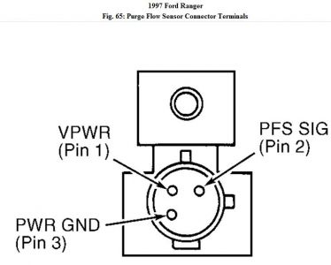
28) Check For Open VPWR Circuit In PF Sensor Disconnect PF sensor. Allow the vehicle and PF sensor to cool down or warm up to room temperature 55-80 °F (13-27 °C) before taking a resistance measurement on the PF sensor. This can take 15-20 minutes. Measure resistance between VPWR pin and PF sensor, PWR GND pins on the PF sensor. See Fig. 65 . If resistance greater than 160 ohms between VPWR and PF sensor pins or greater than 190 ohms between VPWR and PWR GND pins, replace damaged PF sensor. Reconnect any disconnected components. Record data from this step and go to step 42). If resistance is not greater than 160 ohms between VPWR and PF sensor pins or not greater than 190 ohms between VPWR and PWR GND pins, go to next step.
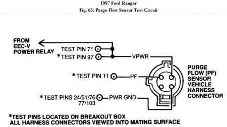
29) Check VPWR For Open Install breakout box, leave PCM disconnected. Measure resistance of VPWR circuit between PCM test pin No. 71 and PF sensor harness connector. If resistance is less than 5.0 ohms, leave breakout box installed. For DTC P1444, go to next step. For DTC P1445, go to step 34). If resistance is not less than 5.0 ohms, repair open circuit. Reconnect any disconnected components. Reset PCM to clear DTCs and repeat QUICK TEST . Verify a symptom no longer exists. Reset PCM to clear DTCs and repeat
QUICK TEST .
30) Check For Short To PWR GND In PF Sensor Disconnect PF sensor. Allow the vehicle and PF sensor to cool down or warm up to room temperature (55-80 °F (13-27 °C)) before taking a resistance measurement on the PF sensor. This can take 15-20 minutes. Measure resistance between PWR GND and PF sensor pins on the PF sensor. If resistance is less than 25.50 ohms, replace damaged PF sensor. Reconnect any disconnected components and go to step 42). If resistance is not less than 25.50 ohms, go to next step.
31) Check PF Circuit For Short To PWR GND Install breakout box, leave PCM disconnected. Disconnect scan tool from DLC. Measure resistance between PCM test pin No. 11 and PCM test pins No. 24 and 103. If both resistances are greater than 10,000 ohms, replace damaged PCM. Reconnect any disconnected components and repeat QUICK TEST . If both resistances are not greater than 10,000 ohms, repair short circuit. Reconnect any disconnected components. Reset PCM to clear DTCs and repeat QUICK TEST .
32) Check PF Sensor Circuit For Intermittent VPWR Open Or PWR GND Short Turn ignition on, engine off. Access EVAPPF PID. Observe EVAPPF PID for an indication of a fault while lightly tapping on PF sensor and wiggling PF sensor connector and harness between sensor and PCM. A fault is indicated by a sudden change in EVAPPF PID voltage (less than 0.14 volt). If a fault is indicated, isolate fault and repair as necessary. Reconnect any disconnected components. Reset PCM to clear DTCs and repeat QUICK TEST . If a fault is not indicated, unable to duplicate or identify fault at this time. Go to CIRCUIT TEST Z , step 1) with the PF PID and a list of possible causes.
33) DTC P1445: Check PF Sensor High Voltage To PCM Disconnect PF sensor. Check for loose pins or broken wires by pulling moderately on the PF sensor and PWR GND circuits at PF sensor harness connector. Repair as necessary. Reconnect PF sensor. Connect scan tool. Turn ignition on, engine off. Access EVAPPF PID. PF sensor input to the PCM range is 0.4-4.8 volts. Turn ignition off. If EVAPPF PID voltage was greater than 4.8 volts, go to next step. If EVAPPF PID voltage was not greater than 4.8 volts, fault is an intermittent DTC P1445. Go to step 39).
34) Check VPWR Resistance For Short To PF Circuit In PF Sensor Turn ignition off. Disconnect PF sensor. Allow the vehicle and PF sensor to cool down or warm up to a room temperature 55-80 °F (13-27 °C) before taking a resistance measurement on the PF sensor. This can take 15-20 minutes. Measure resistance between VPWR and PF sensor pins on the PF sensor. If resistance is 40-230 ohms, go to next step. If resistance is not 40-230 ohms, replace damaged PF sensor. Reconnect any disconnected components and go to step 42).
35) Check PF Sensor Voltage Input To PCM Turn ignition on, engine off. Measure PF circuit voltage between PF sensor harness connector and battery negative post. Turn ignition off. If voltage was greater than 10.5 volts, go to next step. If voltage was not greater than 10.5 volts, go to step 37).
36) Check PF Circuit For Short To VPWR Install breakout box, leave PCM disconnected. Turn ignition on, engine off. Measure resistance between PCM test pin No. 11 and PCM test pins No. 24 or 103. If the voltage is greater than 10.5 volts, repair short circuit. Reconnect any disconnected components. Reset PCM to clear DTCs and repeat QUICK TEST . If the voltage was not greater than 10.5 volts, replace damaged PCM. Reconnect any disconnected components and repeat QUICK TEST .
37) Check PF Circuit For Open Install breakout box, leave PCM disconnected. Measure resistance of PF sensor circuit between PCM test pin 11 and PF sensor harness connector. If the resistance is less than 5.0 ohms, go to next step. If the resistance is not less than 5.0 ohms, repair open circuit. Reconnect any disconnected components. Reset PCM to clear DTCs and repeat QUICK TEST .
38) Check PWR GND Circuit For Open Measure resistance of PWR GND circuit between PCM test pin No. 24 or 103 and PF sensor harness connector. If the resistance is less than 5.0 ohms, replace damaged PCM. Reconnect any disconnected components and repeat QUICK TEST . If resistance is not less than 5.0 ohms, repair open circuit. Reconnect any disconnected components. Reset PCM to clear DTCs and repeat QUICK TEST .
39) Check PF Sensor Circuit For Intermittent PF Open Or VPWR Short Turn ignition on, engine off. Access EVAPPF PID. Observe EVAPPF PID for an indication of a fault while lightly tapping on PF sensor and wiggle PF sensor connector and harness between sensor and PCM. A fault is indicated by a sudden change in EVAPPF PID voltage (greater than 4.80 volts). If a fault is indicated, isolate fault and repair as necessary. Reconnect any disconnected components. Reset PCM to clear DTCs and repeat QUICK TEST . If a fault is not indicated, unable to duplicate or identify fault at this time. Go to CIRCUIT TEST Z , step 1) with PF PID data and a list of possible causes.
40) Inspect CANP Solenoid Circuit For Intermittent Failure Rerun KOEO, KOER Self-Tests and retrieve Continuous Memory DTCs. If DTC P0443 is present in Continuous Memory Self-Test only, go to next step. If DTC P0443 is not present in Continuous Memory Self-Test only, go to step 1).
41) Check CANP Solenoid Circuit Intermittent Open Or Short Install breakout box, leave PCM disconnected. Measure resistance between PCM test pin No. 67 or PCM test pin No. 56 and PCM test pin No. 71, while lightly tapping on the EVAP canister purge valve and observe a resistance change. Wiggle the EVAP canister purge valve connector and vehicle harness between the valve and the PCM, observe a resistance change. If the resistance reading changes to below 30 ohms or above 90 ohms (vehicles with test pin 67) or above 38 ohms (vehicles with test pin 56), isolate fault and repair as necessary. Reconnect any disconnected components. Reset PCM to clear DTCs and repeat QUICK TEST . If the resistance readings do not change, unable to duplicate or identify fault at this time. Go to CIRCUIT TEST Z , step 1) with the resistance readings and list of possible causes.
42) Verification Of EVAP System Repair Using Rotunda EVAP System Leak Tester Plug or tape atmospheric vent cap on EVAP canister (if applicable). Remove fuel filler cap at fuel filler pipe. Install Rotunda Evaporative Emission System Leak Tester (134-00056), including the nitrogen or argon gas supply and pressure regulator. Disconnect and plug fuel vapor hose to PF sensor (or EVAP canister purge valve on Ranger) from intake manifold at the intake manifold vacuum source. Pressurize the EVAP system at 27 in. H2O (6.74 kPa) with tester. Observe tester installation leak self-test for two minutes and then the EVAP system leak test. Listen for a vacuum leak noise and check for substantial fuel vapor odors at isolated areas in the EVAP system. If the pressure applied to the EVAP system holds, remove plug and reconnect fuel vapor hose from PF sensor (or EVAP canister purge valve) at intake manifold vacuum source. Remove EVAP System Leak Tester. Reinstall fuel filler cap. Tighten cap only one eighth turn so that cap initially clicks by sound or touch. Reset PCM to clear DTCs. Access EVAPPDC PID on scan tool. Drive vehicle (including a steady accelerator speed over 50 mph (80 km/h) until EVAPPDC PID shows 75 percent duty cycle). Then maintain approximate speed until duty cycle reaches zero percent. After additional two minute drive, bring vehicle to an idle. Repeat QUICK TEST to verify a symptom no longer exists. If pressure applied to the EVAP system does not hold, go to next step.
43) Check Location Of EVAP System Pressure Leak Systematically isolate area of potential pressure leak. Close off pressure to EVAP system. Disconnect and plug fuel vapor hose from fuel tank at EVAP canister. Apply controlled pressure at 27 in. H2O (6.74 kPa) to the EVAP system with the leak tester. If pressure now holds, diagnose EVAP canister leak. If system pressure cannot hold, close pressure supply to system. Disconnect and plug fuel vapor hose from EVAP canister at EVAP canister purge valve. Again, apply controlled pressure to the EVAP system. If the pressure holds, remove plugs. Reconnect fuel vapor hose at EVAP canister. Return to step 14) to check EVAP canister purge valve integrity on Ranger or step 18) to check EVAP canister purge valve integrity on Mustang. Remove EVAP System Leak Tester. Reinstall fuel filler cap. Reset PCM to clear DTCs. Access EVAPPDC PID on scan tool. Drive vehicle (including a steady accelerator speed over 50 mph (80 km/h) until EVAPPDC PID shows 75 percent duty cycle). Then maintain approximate speed until duty cycle reaches zero percent. After additional two minute drive, bring vehicle to an idle. Repeat QUICK TEST to verify a symptom no longer exists. If the pressure does not hold, remove plugs. Check for fuel vapor hose cracks or fuel vapor valve damage. Examine and secure fuel vapor hose connections to components. Repair or replace as necessary. Remove EVAP System Leak Tester. Reinstall fuel filler cap. Reset PCM to clear DTCs. Access EVAPPDC PID on scan tool. Drive vehicle (including a steady accelerator speed over 50 mph (80 km/h) until EVAPPDC PID shows 75 percent duty cycle). Then maintain approximate speed until duty cycle reaches zero percent. After additional two minute drive, bring vehicle to an idle. Repeat QUICK TEST to verify a symptom no longer exists.
If there are anything that I have left out, let me know anfd I will get them for you.
Nov 22, 2009 at 2:15 AM