FWD CLUTCH ASSEMBLY
Removal (Escort, Probe & Tracer)
Remove air cleaner assembly and fresh air duct. Remove battery and battery tray. Remove transaxle ground straps. Disconnect vehicle speed sensor, park/neutral position switch and back-up light switch connectors. Remove clutch release (slave) cylinder, with hydraulic lines connected, and position aside.
Install engine support. Remove upper transaxle-to-engine bolts. Remove 2 upper starter motor bolts. Remove fuel filter, with fuel lines connected, and position aside. Remove 2 nuts and through bolt from left transaxle mount. Raise and support vehicle. On 2.0L models, remove intake manifold support bracket. On all models, disconnect starter motor "S" and "B" terminal wires and remove starter motor. Drain transaxle fluid. Remove front wheel assemblies.
Remove and discard axle shaft attaching nuts. Remove splash shield. Remove lower crossmember. Remove bolt and nut from left lower control arm ball joints. Pry lower control arm down to separate from steering knuckle. Pull lower edge of spindle outward to separate from end of axle shaft. Using pry bar, separate left axle shaft from transaxle. Install 2 Transaxle Plugs (T88C-7025-AH) between transaxle differential side gears.
NOTE:Failure to install Transaxle Plugs (T88C-7025-AH) may allow transaxle differential side gears to become mispositioned.
Remove opposite end of left axle shaft from steering knuckle and remove from vehicle. On ABS equipped models, remove clips from left wheel speed sensor and nuts from sensor harness mount.
On 2.5L models, disconnect left and right oxygen sensor connectors. Remove and discard 3 converter inlet pipe-to-exhaust manifold nuts from exhaust converter inlet pipes. Lower exhaust system to gain access to right axle shaft support bearing. Remove 3 right axle shaft support bearing bolts. On ABS equipped models, remove clips from right wheel speed sensor and nuts from sensor harness mount.
On all models, remove bolt and nut from right lower control arm ball joints. Pry lower control arm down to separate from steering knuckle. Pull lower edge of spindle outward to separate from end of axle shaft. Using pry bar, separate right axle shaft from transaxle. Install 2 Transaxle Plugs (T88C-7025-AH) between transaxle differential side gears.
NOTE:Failure to install Transaxle Plugs (T88C-7025-AH) may allow transaxle differential side gears to become mispositioned.
Remove transaxle cradle. Disconnect transaxle shift linkage and extension bar from transaxle. Remove transaxle mount-to-transaxle bolts. Position transaxle jack under transaxle, and secure transaxle to jack. Remove rear transaxle mount. Remove lower transaxle-to-engine bolts. Separate from engine and lower transaxle out of vehicle.
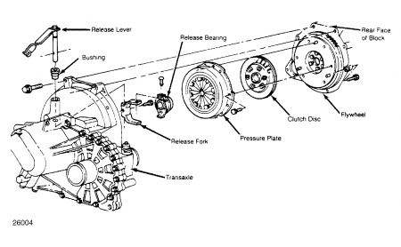
If installing same pressure plate, index mark pressure plate to fly-wheel. See Fig. 1 . Install Flywheel Holder (T84P-6375-A). Loosen pressure plate attaching bolts evenly in a crisscross sequence. Remove pressure plate and clutch disc from flywheel. Remove release bearing and clutch release fork.
Mount a dial indicator so tip of indicator is against outer clutch disc-to-flywheel contact surface of flywheel. Position pry bar between rear crankshaft flywheel mounting flange and engine block. Pry crankshaft fully rearward. With crankshaft still fully rearward, rotate crankshaft one complete revolution while noting variation of reading on dial indicator which indicates runout. See FWD FLYWHEEL SPECIFICATIONS (ESCORT, PROBE & TRACER) table.
FWD FLYWHEEL SPECIFICATIONS (ESCORT, PROBE & TRACER)
ApplicationRunout Limit In. (mm)
Escort & Tracer
1.8L .008 (.20)
1.9L .007 (.18
Probe .008 (.20)
If runout exceeds specification, use a crisscross sequence to loosen flywheel bolts. Remove flywheel. Repeat runout reading procedure as in step 9), except place dial indicator tip against crankshaft rear flange face. If crankshaft rear flange is cause of excessive runout, resurface crankshaft flange face or replace crankshaft. If flywheel is cause of excessive runout, resurface or replace flywheel.
Feb 19, 2009 at 9:18 PM
