Radio will not turn on?

Tiny
MICHELLE SAN ANTONIO
  • MEMBER
  • 1993 DODGE DAKOTA
  • 5.6L
  • V8
  • 2WD
  • AUTOMATIC
  • 128,000 MILES
Radio will not turn on. Power confirmed to clock and tape deck. Unable to reset clock. No sound/static. Similar issue as described in your post in the attached image. Fuses are fine. I’d like to send you the radio for repair if possible. Model #7910
Tuesday, June 10th, 2025 AT 6:32 AM

9 Replies

Tiny
CARADIODOC
  • MECHANIC
  • 34,178 POSTS
I'd be happy to look at your radio, but depending on the model you have, there may be some "work-arounds" you can do yourself. The one I saw most often was the bad contacts on the volume control / power switch. If you can describe what the face of your radio looks like, or if you know the model number, that will get me started.

If you have the base radio, with or without cassette, volume control in the upper left, with a click-type power switch, and the tuning knob is in the lower left, look for a wire in cavity number 1 in the black plug. That's on the opposite end as the keyway. I have that listed as a dark green / red wire, but those colors can vary on different car models and years. Next, remove that black plug, then look if there is a pin in the radio's connector corresponding to that wire. If you have that pin and wire, this trick will work.

The base radio was never used with a remote amplifier, however, the wire was often found in the plug in case the dealer switched to an upgrade radio model. That circuit is the turn-on circuit for a remote amp and for a power antenna. Generally, the base radio didn't include a power antenna, so they left pin number 1 out of the radio's plug. If the pin is missing, you have to go inside the radio to do this modification. If the pin is there, all you have to do is connect the two wires in the two plugs.

The circuits in question are the red or the red / white wire in cavity number 6 in the gray plug, and the dark green / red wire in cavity number 1 in the black plug. The first one is the 12-volt feed from the ignition switch. When the radio's switch is turned on, it turns on the radio and it puts 12 volts onto the dark green / red wire to turn on the amplifier and / or power antenna. By connecting these two wires together, you're just shorting the power switch in the radio so it's always on when the ignition switch is on. If you don't want the radio on, just turn the volume all the way down.

There's another potential problem that involves burned contacts on the ignition switch. There's actually three or four separate circuits and switches built into the ignition switch. It's the one that controls "accessory" circuits that causes the problem, but usually other symptoms are mentioned first. Most commonly the heater fan and wipers don't work. The radio is on that circuit too. This problem happens most often to people in the habit of turning the ignition switch on and off while the heater fan is set to one of the higher speeds. That causes a lot of arcing in the ignition switch. I can get a lot more involved if it looks like you need to replace that switch. Another common complaint related to that is if you have a cassette player and power windows, the tape player would "change direction when both windows were rolled down at the same time". What was really happening was the window motors draw higher current when the windows bottom out and lock up momentarily. The higher current causes a higher voltage drop across the burned ignition switch contacts. The radio interprets that incorrectly as you turned off the ignition switch. In response, it retracts the capstan pinch roller and heads. When you release the power window switches, voltage to the radio goes back up, and the cassette player resumes operation. It just sounded like it reversed. A new ignition switch solves this for a while, but there's more to the repair to prevent a repeat failure.

See if any of those ideas leads to anything, and let me know if you need help inside the radio. I've told others how to short the two wires together, but I've never actually done it myself. I always repaired the power switches. Inside the radio, you'll find the soldered connections from the pins in the two plugs. If you're familiar with working on circuit boards, you'll know what to look for. You can solder in a jumper wire between those two points. If your radio isn't like I described, you'll have to remove it, then find me the model number. It will be on a paper sticker.
Was this
answer
helpful?
Yes
No
Tuesday, June 10th, 2025 AT 3:19 PM
Tiny
MICHELLE SAN ANTONIO
  • MEMBER
  • 5 POSTS
Yes, the radio is as you described, with the cassette deck. I pulled it out last year to see if there was anything noticeably wrong to my novice eyes and I took a pic of the sticker there. Model # 5269414 Issue BKGS 11 (or II) Date Code 2182 Serial # 235862 Supplier 7910

My heater and wipers work fine. I don’t know if the windows are affected by the radio and vice versa since the radio doesn’t work. There is a static antenna, not powered.

Unless you can offer more specific instruction based on the information I gave you from the sticker, I’ll start at the top of your list and troubleshoot. Will any of this help me reset the clock since the select buttons are part of the radio features?

Thank you! I’m very appreciative of the advice. I have some Rolling Stones tapes to listen to!
Was this
answer
helpful?
Yes
No
Tuesday, June 10th, 2025 AT 5:35 PM
Tiny
CARADIODOC
  • MECHANIC
  • 34,178 POSTS
It sounds like the radio's power switch needs to be repaired. Did you check for the presence of that last terminal in the black plug, and / or the last wire in that plug? You don't have to calculate which wire I'm referring to. You'll have all seven wires in the gray plug. You'll have either six or seven in the black plug. If you have all seven, installing a jumper wire will be easier. If that one wire is missing, I'll put together a drawing of which points to add a jumper wire to inside the radio, if you're up to soldering.

Without being able to turn the radio on, you can remove the interior lights fuse, (with ignition switch off), or disconnect the negative battery cable, then reinstall or reconnect at 12 noon or 12 midnight. The radio defaults to 12:00 when power is restored.
Was this
answer
helpful?
Yes
No
Wednesday, June 11th, 2025 AT 8:20 PM
Tiny
MICHELLE SAN ANTONIO
  • MEMBER
  • 5 POSTS
Ok thanks! I’ll try to pull it apart this weekend and I will get back to you.
Was this
answer
helpful?
Yes
No
Thursday, June 12th, 2025 AT 8:01 AM
Tiny
CARADIODOC
  • MECHANIC
  • 34,178 POSTS
I have to apologize. Adding a jumper wire inside the radio is not practical. I mentioned I never actually did this myself, and I remember why now. Removing the switch to repair it is a tedious job, but far easier than removing the circuit board. That board has to be removed to get to the points that must be connected.

According to the service manual, your model has all seven terminals in the black plug, so there's two ways you can approach this. Look in the gray plug for terminal # 2. That will be a red wire, with or without a stripe. That's one of the two you need. In the black plug, look for wire # 7, usually a dark green / red, on the end opposite the keyway. That's the second wire. The easiest thing to do is strip a little insulation from each, then solder a jumper wire between them. That will short out the radio's power switch so it's always on, just as if you left the switch turned on all the time.

If you find the wire is missing from terminal # 7 in the black plug, double-check the pin is in the radio's connector, then look closely at that plug because there were a number of different styles, I suspect from different suppliers, over the years. Head to a pick-your-own-parts salvage yard and find a plug that looks the same. There will be all kinds of vehicles with the radios already removed, so examining plugs will go pretty fast. Cut off either plug, and leave a good six inches of wire with it.

At home, there will be a locking wedge, often dark green, that can be pried and pushed out, then you need a small pick to reach in the little square opening under the terminal to lift a plastic finger. That allows you to pull that terminal out. The reason for finding an identical plug is to insure the terminal is the same and will fit easily into place.

Remove the locking wedge in your vehicle's plug, then slide the new terminal in. It will click into place, then reinstall the locking wedge. Attach that wire to the red one. The terminals will be the same in both plugs, and you can use any color wire.

To seal the soldered splice, my preference is to remove the red wire from its plug, then slide on a piece of heat-shrink tubing. If you find that's rather difficult, use some silicone gasket sealer and make a little ball of it around the splice. I don't like electrical tape in cars because it will unravel into a gooey mess on a hot day. The heat-shrink tubing doesn't have to be the moisture-proof kind with hot-melt glue inside. The terminals aren't sealed, and inside, that isn't necessary.
Was this
answer
helpful?
Yes
No
Friday, June 13th, 2025 AT 11:27 AM
Tiny
MICHELLE SAN ANTONIO
  • MEMBER
  • 5 POSTS
With help, I discovered the following information:
There is not a wire in #7 on black plug.
#1 wire (pink) in gray plug is not hot. A jump wire was applied to this pink wire while the plug was inserted in radio and did affect the display- not able to reset clock or change AM/FM, change to different channels.
#2 wire (red/white stripe) is hot

I pulled the cover off the radio and the only noticeable thing is the resistor has slight discoloration, but the solder points are intact. Attached are pictures.

I’ve left the radio disconnected for the time being.
Was this
answer
helpful?
Yes
No
Saturday, June 14th, 2025 AT 7:33 AM
Tiny
CARADIODOC
  • MECHANIC
  • 34,178 POSTS
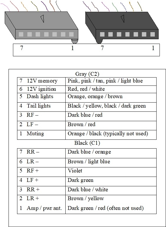
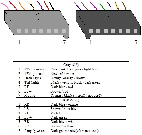
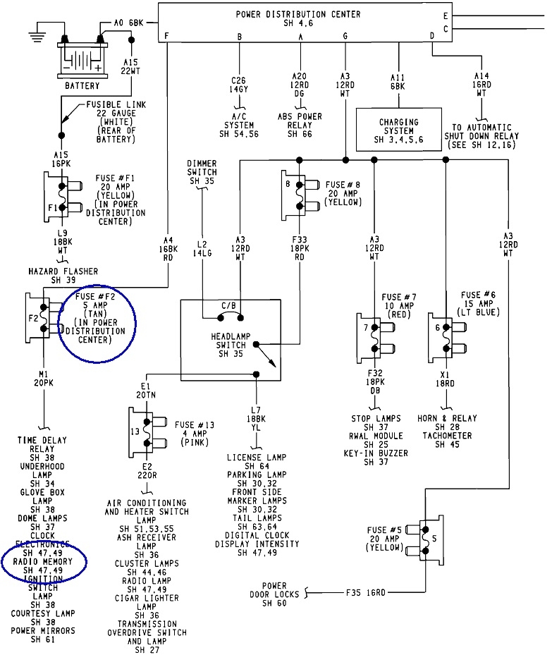
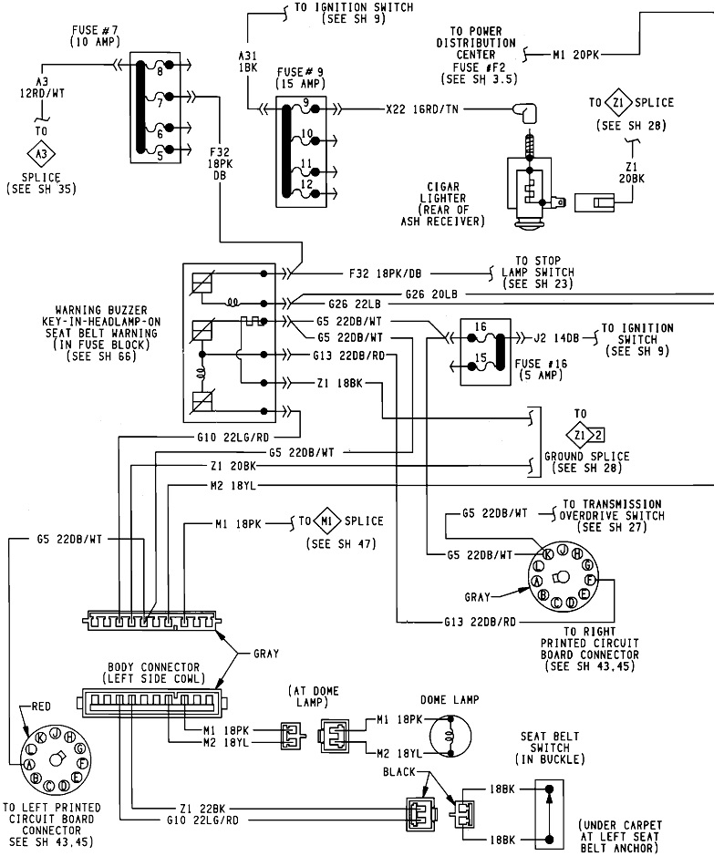
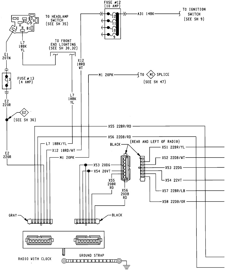
Something's wrong. Either a fuse is blown or your meter probes didn't make good contact. The pink wire is for memory 12-volts and must be there all the time. If its fuse is blown, the interior lights won't work either. The various radio models act differently when there's no memory 12 volts. Some turn on with the ignition switch and work fine, until you turn the ignition switch off and back on. Then, it will revert to 12:00 and the factory default station presets. Some models appear to tune and run the cassette mechanism, but there's no sound. Others will be completely dead, including the display. I gave up trying to remember how each model acts when that memory circuit is dead. At any rate, investigate that first.

The red / white wire next to the pink one only has 12 volts when the ignition switch is in "run" or "accessory". It's rare for that to be missing as you'd have a number of other symptoms.

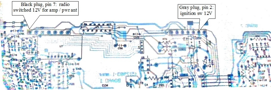
The blue arrow in your photo verifies that seventh terminal is in the radio, as shown in my service manual. If the wire is not in the plug, the best approach is to add that wire like I described. Be sure to find a connector that looks the same. All of them from the mid 1980s to as late as a few 2003 models use gray and black plugs that plug into any radio, but it's their terminals that can be different. Terminals from different style plugs won't slide into the plug or click into place. These terminals can be a little tricky to remove, so practice on the plug you get from the salvage yard first. Some terminals just have a square hole on one side, then a plastic finger drops into it to hold the terminal in. You have to go in from the radio-side of the plug with a thin pick or terminal removing tool to lift that finger, then pull the terminal out by the wire. A small sewing needle works too.

Another style of terminal has part of it stamped and bent out to create a little spring tab that holds it in. You go in through the same radio end of the plug with a thin flat blade to push that tab up while pushing in on the wire. Once the tab is pressed up, you can pull the terminal out. When you get frustrated, if you pull too hard, the terminal will come out but the tab will be bent backward. If it doesn't break off, you can bend it back. Leave it sticking out a little so it can click into place.

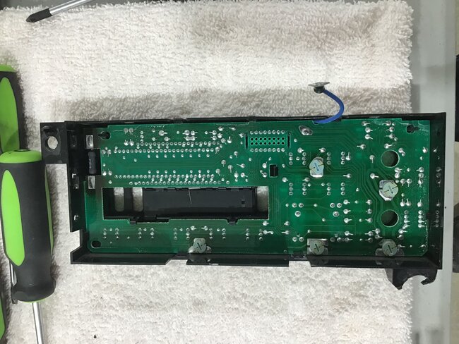
The reason adding an internal jumper wire is so difficult is removing the circuit board involves unsoldering a number of ground standoffs. My red arrow is pointing to one of them. To get to most of the others, you have to peel back the two pieces of tape, (orange arrow), and some models have another layer of white tape that covers the entire cover. For those, I just poke a hole through that tape. Other standoffs may or may not be soldered, but you have to untwist them with a quarter turn on the other side of the board once the cassette mechanism is removed, (pink arrow).

I should also mention, when taking voltage readings, poke your meter's probe into the back of the plugs alongside the wires. The holes in the radio side are usually too small for meter probes to get in far enough, and it's too easy to spread a terminal by inserting a probe tip that's fatter than the terminal that normally slides in there. If I have to go into a terminal in a sealed plug, I use a sewing needle to touch that terminal. A spread terminal can cause intermittent operation of that circuit.

Since you obviously know a lot more about electronics than the average person, you can also do a continuity check of the radio's power switch. Remove the black plug from the terminal adapter, plug that adapter back into the radio, then measure from the terminals corresponding to the two wires. I do this with the radio unplugged to insure I'm not reading through any other circuitry. If you have a pair of small jumper wires, (clip leads), you can use those to connect the meter probes, leaving your hands free to run the power switch.

If the switch contacts are bad, you might get a reading in the Kohm range, but it's supposed to be 0 ohms when the switch is on. On the higher Ohms scales, often you'll see the reading flicker slightly between "over range" to "something" for just an instant when the switch is turned on. Even if you do get a very low reading, the contacts can still be bad. Ohm meters pass very little current to do their thing. Burned contacts that read 0 ohms may still not be able to pass enough current to power the radio.

If you want to tackle repairing the power switch, I can go into a lot more detail. You'll need a wire cutter with a small, very thin tip to open the band around the control. Since you have this apart already, you'll see the control on the small board on the side that's flopping around via a ribbon cable. You'll see the two tabs bent over on the back of the volume control. Those are what you must bend straight so the rear plate can be slid off.

The problem stemmed from the spring-loaded movable contact would bump up against the plastic housing it sits in just as the contacts touched. With a little normal arcing over time, that housing prevented the contacts from having enough pressure to hold them applied. My repair involves sanding those contacts first to clean them up. Next, I bend them just a little so they make contact before the flipper has to move all the way. That makes them make contact before the flipper gets close to the plastic housing. Last step is to sand the contacts again so they have a larger surface area to pass current easier. This can all be done without removing the entire control assembly, but you will need a desoldering tool or solder wick to remove the switch. Fortunately the switch is the rear-most segment on the control.

The sandpaper I use is a very fine grit wet / dry that I get from a friend. If you want to pursue this, I'll try to find one of these I have apart already, and take some photos.
Was this
answer
helpful?
Yes
No
Saturday, June 14th, 2025 AT 3:48 PM
Tiny
MICHELLE SAN ANTONIO
  • MEMBER
  • 5 POSTS
I checked and rechecked the radio fuse and it’s fine. Is there another one I’m overlooking?

#7 pin in black plug doesn’t have a green wire and looks like it was never part of the wiring harness. This truck model doesn’t have a power antenna.

#1 pink wire in gray plug does not have power when tested with test light. A jumper wire with test leads was inserted into the #1 cavity with the plug inserted and nothing changed- EXCEPT- the clock blipped briefly. I was still unable to reset clock, change AM/FM, tune to stations.

#2 red/white wire is confirmed hot with test light. I’ve never had trouble with the interior lights, windows, wipers, or blower fan. In fact the interior lights are still out since I have the radio unplugged.

We haven’t used a voltage meter yet, and that’s a good suggestion.

My helper is pretty ok with electronics, but soldering connecting points, etc, may be a little out of our knowledge base. Stay tuned- ha!
Was this
answer
helpful?
Yes
No
Sunday, June 15th, 2025 AT 7:53 AM
Tiny
CARADIODOC
  • MECHANIC
  • 34,178 POSTS
Yes, there's two power sources and two fuses. Check the 5-amp Interior Lights fuse. That supplies the radio's memory circuit. It has to be there for the radio to work right.

I apologize for trying to follow these diagrams backward. This is much easier with paper service manuals. This first one shows part of the power distribution system, including the memory fuse feeding the pink wire. The next two are for Interior Lighting, but I didn't try to follow it to see if I have all the pages. I'll study them at home, later. The last two are for the 2-speaker radio system.

The missing # 7 wire is the one I described earlier that you have to add. The terminal is in the radio's plug, but not in the connector. That's the one to find in a salvage yard. Once you add that wire, connect it to the red /white wire in the gray plug.
Was this
answer
helpful?
Yes
No
Sunday, June 15th, 2025 AT 7:47 PM

Please login or register to post a reply.