Welcome to 2CarPros.
The ETS light(enhanced traction system is likely related to a wheel speed sensor. As far as a code, it requires a scanner that can read all types and not just power-train.
Now, the first thing I suggest is to check the wheel speed sensors. Here is a link that shows how it is done:
https://www.2carpros.com/articles/abs-wheel-speed-sensor-test
You will need to use a volt meter or multi meter to test this. Here are a couple links you may find helpful:
https://www.2carpros.com/articles/how-to-use-a-voltmeter
https://www.2carpros.com/articles/how-to-check-wiring
__________________________
Now, if you determine there is a bad sensor, here are the directions for replacement. The attached pictures correlate with these directions.
__________________________
Front sensors
WHEEL SPEED SENSOR REPLACEMENT (FRONT)
REMOVAL PROCEDURE
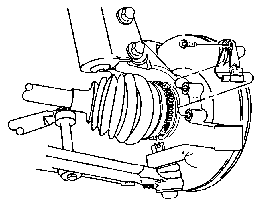
picture 1
1. Raise and support the vehicle on a suitable hoist.
2. Disconnect the front wheel speed sensor electrical connector.
3. Remove the retaining bolt.
IMPORTANT: If the sensor locating pin breaks off and remains in the knuckle during removal, proceed as follows:
3.1.Remove the brake rotor and remove broken pin using a blunt punch.
3.2.Clean the hole using sand paper wrapped around a screwdriver or other suitable tool. Never attempt to enlarge the hole.
4. Remove the front wheel speed sensor. If the sensor will not slide out of the knuckle, remove the brake rotor and use a blunt punch or equivalent tool in order to push the sensor from the back side of the knuckle.
INSTALLATION PROCEDURE
picture 1
1. Install the front wheel speed sensor to the steering knuckle.
NOTICE: Refer to Fastener Notice in Service Precautions.
2. Install the retaining bolt.
Tighten the Torx screws to 12 Nm (107 inch lbs.).
3. Connect the front wheel speed sensor electrical connector.
4. Lower the vehicle.
5. Perform the A Diagnostic System Check - ABS.
__________________________
If you determine one of the rear are bad, that requires replacement of the hub assembly. The sensor is an integral part and not replaceable by itself.
Here are the directions.
REAR WHEEL BEARING/ HUB
REMOVAL PROCEDURE
1. Raise and support the vehicle. Refer to Vehicle Lifting.
2. Remove the tire and wheel assemblies. Refer to Tire and Wheel Removal and Installation in Wheels, Tires and Alignment.
Notice: Do not hammer on brake drum as damage to the bearing could result.
3. Remove the brake drum. Refer To Brake Drum Replacement in Drum Brakes.
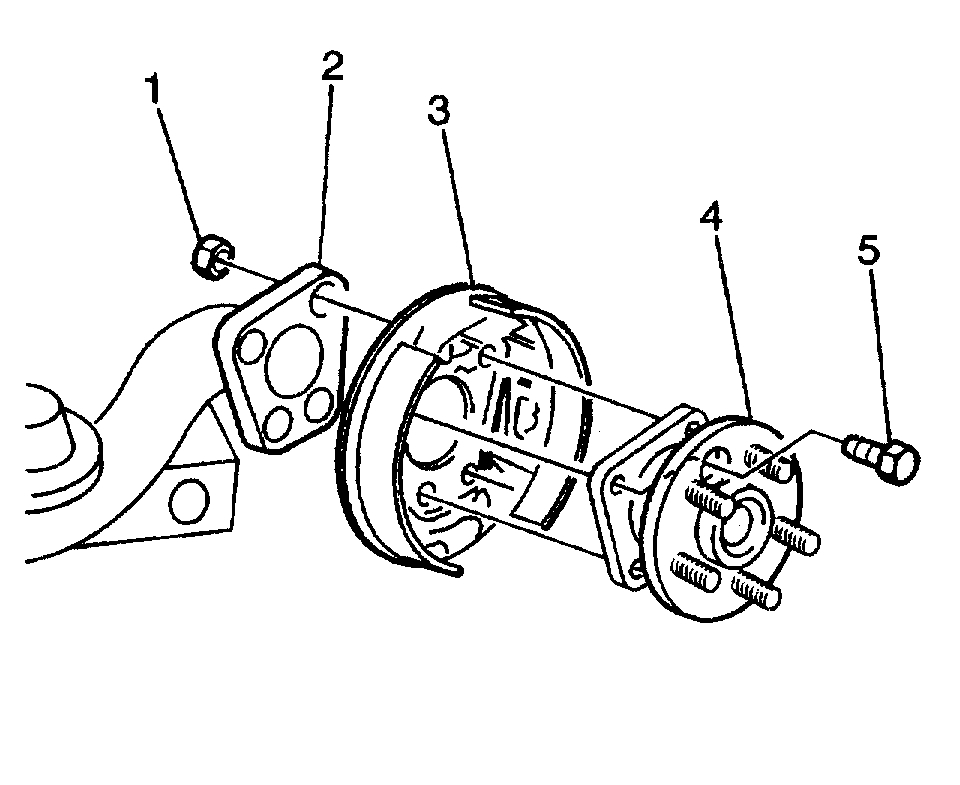
picture 2
4. Remove the hub and bearing assembly (4) from the axle (2). The top rear attaching bolt (5) and nut (1) will not clear the brake shoe (3) when removing the hub and bearing assembly. Partially remove the hub and bearing assembly prior to removing this bolt.
5. Disconnect the rear ABS wheel speed sensor wire connector.
INSTALLATION PROCEDURE
1. Connect the rear ABS wheel speed sensor wire connector.
picture 2
2. Install the hub and bearing assembly (4). Position the top rear attaching bolt (5) in the hub and bearing assembly prior to the installation in the axle assembly (2).
Tighten the hub and bearing to axle bolts to 60 Nm (44 ft. lbs.).
Notice: Refer to Fastener Notice in Service Precautions.
3. Install the brake drum. Refer to Brake Drum Replacement in Drum Brakes.
4. Install the tire and wheel assemblies. Refer to Tire and Wheel Removal and Installation in Wheels, Tires and Alignment.
5. Lower the vehicle.
________________________________
Let me know if this helps.
Joe
Images (Click to make bigger)
Friday, April 26th, 2019 AT 8:19 PM