DTC P1870: TRANSAXLE COMPONENT SLIPPING
Circuit Description
PCM monitors Torque Converter Clutch (TCC) slip speed by calculating difference between engine speed and transaxle output speed. While driving with transaxle in "3" position and TCC engaged, engine speed should closely match transaxle output speed.
DTC P1810 is set when PCM detects excessive TCC slip of TCC, forward clutch and direct clutch when TCC is engaged in 3rd gear.
Conditions For Setting DTC P1870
DTC will set under the following conditions:
DTCs P0122 and P0123 (throttle position), or P0502 and P0503 (vehicle speed sensor) are not present.
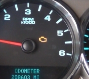
Engine speed is 1500-3600 RPM.
Throttle position angle is 10-50 percent.
TCC is on for 5 seconds or more.
TCC slip speed is more than 140 RPM for 8 seconds.
Speed ratio is.90-1.375.
Vehicle speed is 35-75 MPH.
All conditions are met one or more times.
Action Taken By PCM
PCM performs the following if DTC is set:
Illuminates MIL when fault is set.
Inhibits TCC engagement.
DTC P1870 will be stored in PCM history.
Diagnostic Procedure
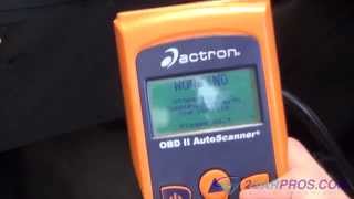
Connect scan tool to DLC. Turn ignition switch to ON position. DO NOT start engine. Using scan tool, record freeze frame and failure records for reference. Data will be lost when DTCs are cleared later in this test.
Drive vehicle in "3" position with TCC engaged. Record TCC slip speed when transaxle is in 3rd gear with TCC engaged. Select snap shot mode on scan tool. Record TCC slip speed. When TCC is engaged, TCC slip speed should be more than 150 RPM. If RPM is as specified, go to next step. If RPM is not as specified, see DIAGNOSTIC AIDS.
Turn ignition switch to OFF position. Disconnect transaxle wiring harness connector. Connect test light between ground and Pink wire on engine side of transaxle wiring harness connector. Turn ignition switch to ON position. If test light is on, go to next step. If test light is off, check Pink wire for open between connector and fuse block. Repair as necessary, and then go to step 11.
Connect test light between battery positive and Tan/Black wire on engine side of transaxle wiring harness connector. Using scan tool, command TCC solenoid on several times. If test light is on when TCC solenoid is commanded on, go to next step. If test light is off when TCC solenoid is commanded on, check Tan/Black wire for open between PCM and TCC solenoid. Repair wire as necessary, and then go to step 11. If wire is okay, replace PCM, and then go to step 11.
Ensure fluid level is correct. Inspect manual linkage for misadjustment or binding. Inspect throttle valve cable for misadjustment, binding or broken cable. Repair components as necessary, then go to step 11. If components are okay, go to next step.
Check for low line pressure. See HYDRAULIC PRESSURE TESTS in HYDRA-MATIC 3T40 OVERHAUL article. If line pressure is within specification, go to step 8. If line pressure is not within specification, go to next step.
Check for restricted oil filter or missing or damaged filter seal. Check for missing pressure relief valve check ball. Check for damaged pressure relief valve or pressure regulator valve springs. Check pressure regulator valve for nicks or scored surface. Check for sticking pressure regulator valve. Check oil pump seals for wear or damage. Check for stuck oil pump slide, vane or drive damage. Repair components as necessary, and then go to step 11. If components are okay, go to next step.
Ensure TCC solenoid check ball is seating properly. Ensure converter clutch control valve is not stuck in off position. Repair components as necessary, and then go to step 11. If components are okay, go to next step.
Check for worn or damaged turbine shaft seal. Check for damaged torque converter. Repair as necessary, and then go to step 11. If components are okay, check direct clutch for missing No. 5 check ball, damaged driven sprocket support seals, burned clutch plates, sticking exhaust check ball, or damaged, worn or missing piston seals. Repair components as necessary, and then go to step 11. If components are okay, go to next step.
Check forward clutch for restricted spacer plate orifice, burned clutch plates, or worn or damaged piston seals. Repair components as necessary, and then go to next step.
After repair is complete, select DTC on scan tool. Select "Clear Info" function. Select "Specific DTC" and enter DTC P1870. Drive vehicle in "3" position with throttle position angle at 10-50 percent and vehicle speed at 40-55 MPH with TCC commanded on. TCC slip speed must be between -20 and 40 RPM for 3 seconds. If DTC P1870 is not present, repair is complete. If DTC P1870 is still present, repeat test.
Diagnostic Aids
Inspect wiring for poor connections at PCM and at transaxle wiring harness connector. Check for bent, backed out, deformed or damaged terminals. Check for weak terminal tension. Check for chafed wires that could short to bare metal or other wiring. Inspect for broken wires inside insulation. Verify final drive ratio is correct for specific vehicle. Check for vehicle overloading or trailer towing beyond vehicle capacity (if applicable).
COMPONENT TESTS
TCC SOLENOID
NOTE:When diagnosing converter clutch problems, ensure engine and vacuum systems are operating properly. Some solenoids have an internal pressure switch in series with the solenoid winding and will not show continuity until that pressure switch is applied by transaxle hydraulic pressure.
Disconnect harness connector to Torque Converter Clutch (TCC) solenoid. Measure resistance between TCC solenoid terminals "A" and "D". See WIRING DIAGRAMS. Resistance should be 19-31 ohms. If resistance is not as specified, replace TCC solenoid.
Tuesday, April 6th, 2010 AT 7:39 PM