While driving engine shuts off

Tiny
YASIRDAHHAM
  • MEMBER
  • 186 POSTS
It is late night now. I did some test to check continuity for the 3 pins of the connector of the pressure switch/fuel pump control switch of my car. As you can see, it is a 3-wire connector to fit the 3-pins pressure switch attached to my cylinder head end. The colors are pale but look like (red- pink and brown). The brown wire gave no electricity as you can see in the images attached to this comment and what follows it, the rest of wires gave a (live) test but one wire made the test tool glow like a sun while the other made it glow faintly.
Was this
answer
helpful?
Yes
No
Saturday, June 12th, 2021 AT 2:41 PM
Tiny
YASIRDAHHAM
  • MEMBER
  • 186 POSTS
The 2nd test pin.
Was this
answer
helpful?
Yes
No
Saturday, June 12th, 2021 AT 2:42 PM
Tiny
YASIRDAHHAM
  • MEMBER
  • 186 POSTS
The 3rd and final test pin.
Was this
answer
helpful?
Yes
No
Saturday, June 12th, 2021 AT 2:42 PM
Tiny
JACOBANDNICKOLAS
  • MECHANIC
  • 108,179 POSTS
Hi,

I dug through several schematics and finally found the one with a 3 wire oil pressure switch. According to the schematic, the wires are pink, gray, and tan. Tan goes to the IP, so that shouldn't have power as you mentioned. The pink wire is powered via a 20 amp pump/injector fuse and should provide 12v (bright light) when the key is in the run position. The gray wire should also have 12v when the fuel pump relay and oil pressure is present, but nothing, when there is no pressure and the relay, is not actuated. You are getting a small amount of power there. Something is shorting to the gray wire. Trace the gray wire back to the fuel pump relay and check for a short to power. Or, the fuel pump relay is bad. Remove the relay and inspect the pins in the box. Check the relay. Here is a link that explains how it's done:

https://www.2carpros.com/articles/how-to-check-an-electrical-relay-and-wiring-control-circuit

If the tan wire was cut, that will prevent the gauge from working. Also, it won't bypass the oil pressure switch's signal for the fuel pump to work or not to work.

See pics below. The pictures are from General Motors (Pontiac Division). I'm hoping the wire colors you are seeing match.

Let me know.

Joe

See pics below.
Was this
answer
helpful?
Yes
No
+1
Saturday, June 12th, 2021 AT 8:41 PM
Tiny
YASIRDAHHAM
  • MEMBER
  • 186 POSTS
This is a great dispatch! I will take some time to go through the 3 attachments comparing the wires to my own, and yes it is (tan) color, I used the (brown) instead, I apologize for that, I am attaching a daytime photo for the 3 wires, the colors are pale since these are the original wires for a 26 years old automobile so I cared to make the connector visible too. I am so grateful for the great assistance you are providing, such a wonderful site that I needed to get acquainted with so long ago.
.
Was this
answer
helpful?
Yes
No
Sunday, June 13th, 2021 AT 12:06 AM
Tiny
YASIRDAHHAM
  • MEMBER
  • 186 POSTS
Alternatively, when I dismantled the whole dashboard some 2 weeks ago and came out with that blue controller for chimes, I found one loose connector that is like a lone wolf, no mating part to find around the location where it was hanging down to the right side of the DLC and a bit deep near to the front side of the compartment. Any idea what is it? Does it relate to any component, controller or relay may be? I am attaching two other images for the DLC of my car, it had no live power in any of the 3 wires, hence the (no communication with scanner) that I used to get every time I be scanning through the DLC.
Was this
answer
helpful?
Yes
No
Sunday, June 13th, 2021 AT 12:15 AM
Tiny
JACOBANDNICKOLAS
  • MECHANIC
  • 108,179 POSTS
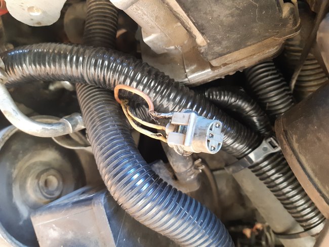
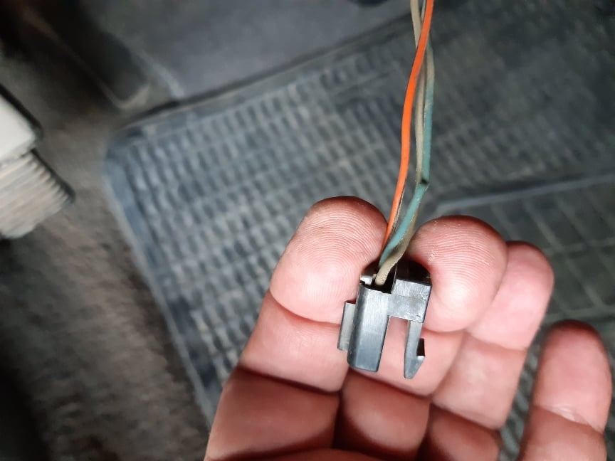
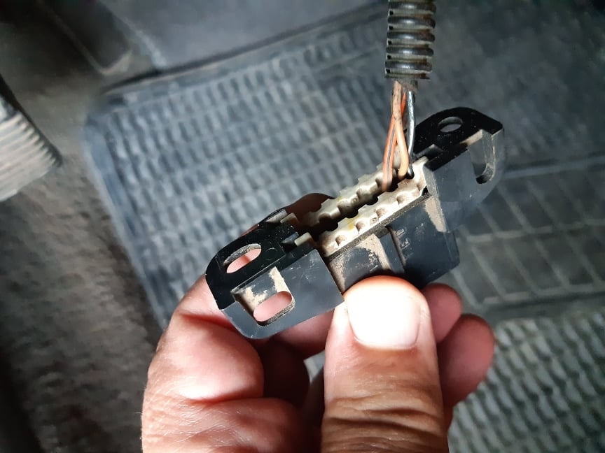
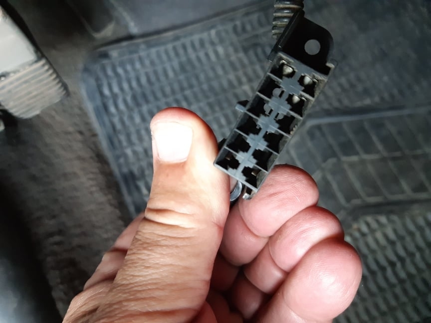
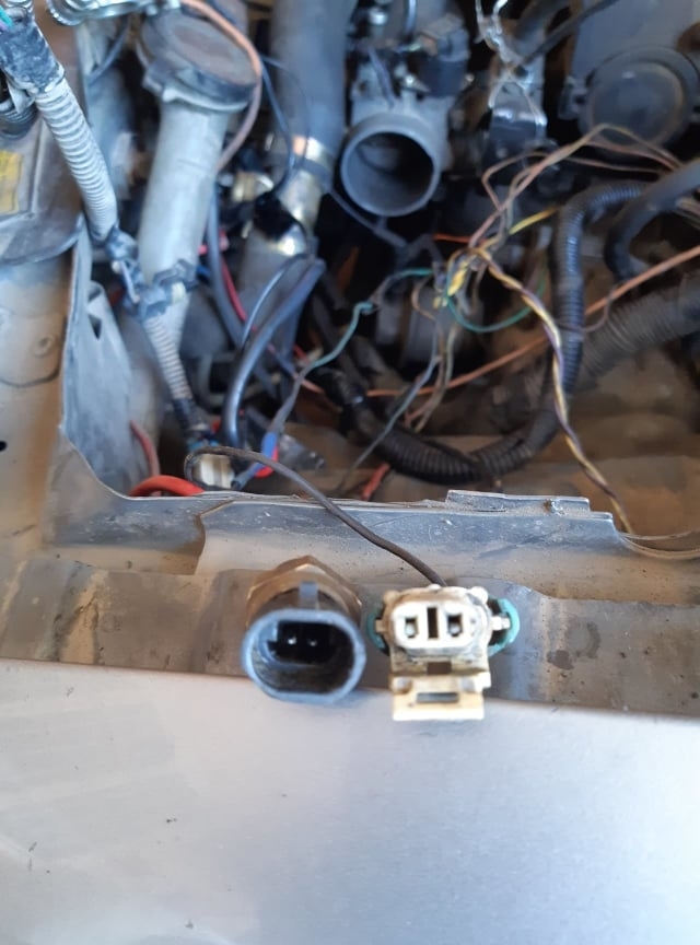
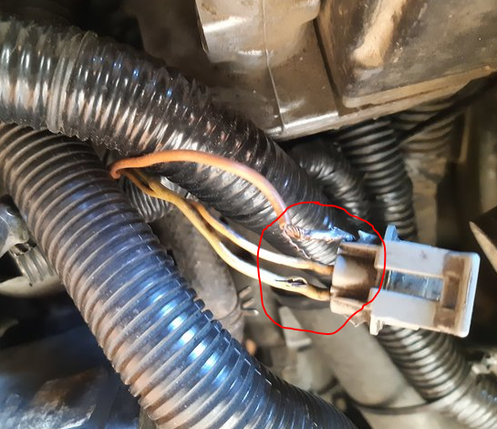
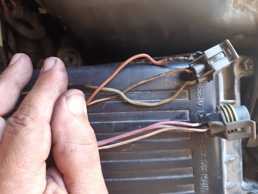
Did the vehicle come with a factory alarm? I believe that is a connection for it. The one wire appears orange, is that correct? The other two is one blue? It looks damaged in the pic, and the last one gray or tan?

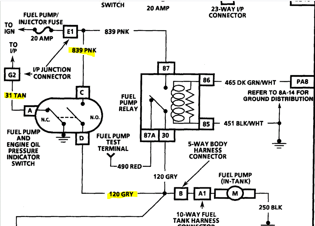
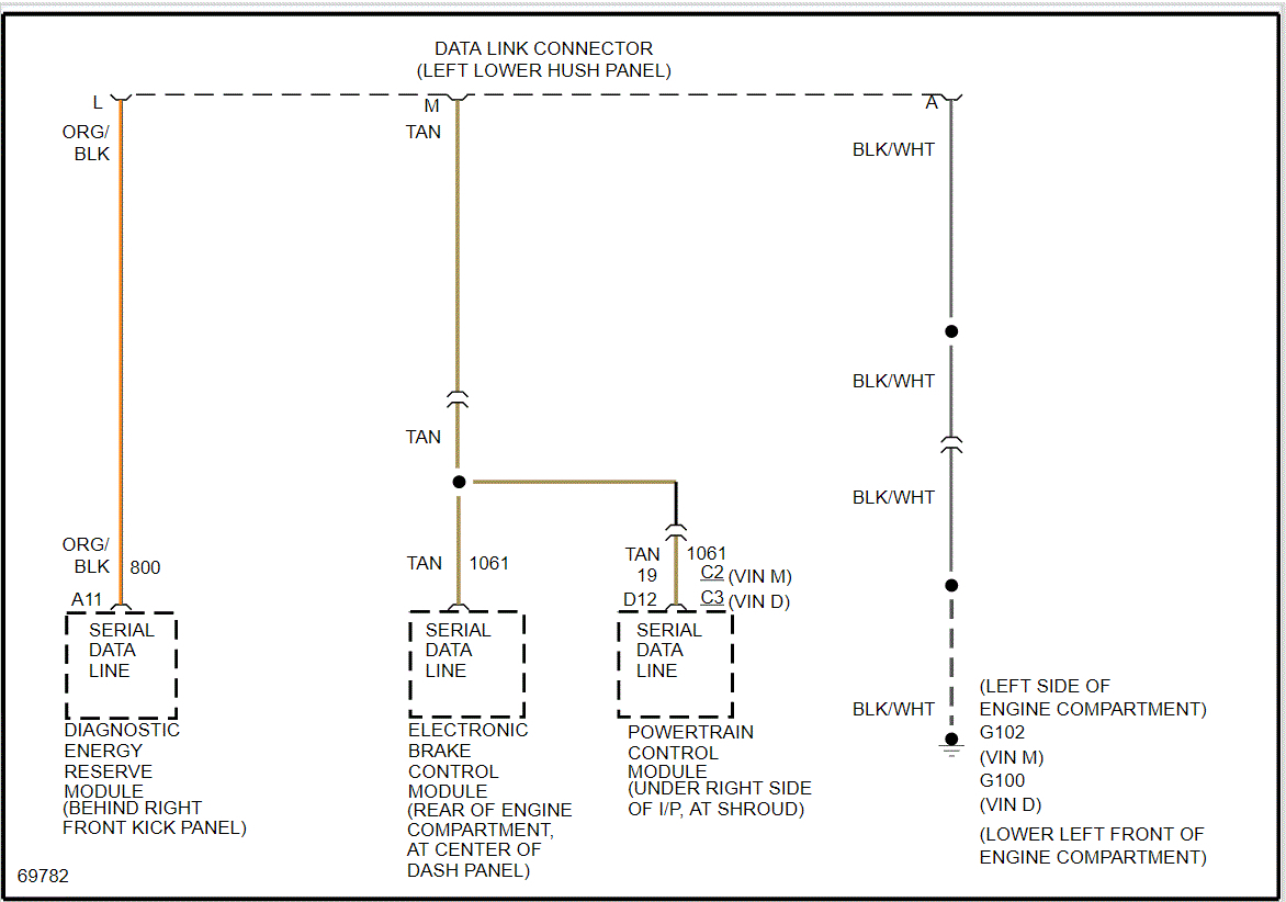
As far as the DLC, those are the correct color wires. The black one with a white tracer should have continuity to ground. See pic 1 below.

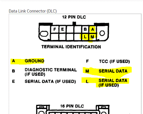
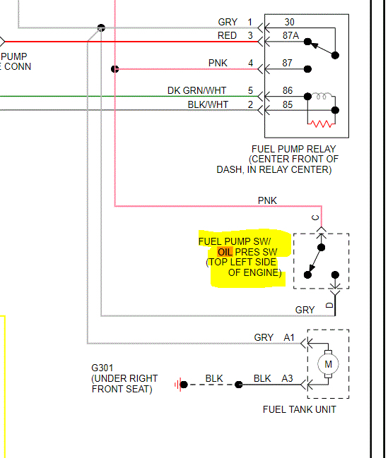
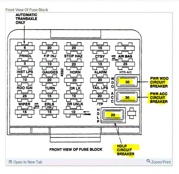
Pic 2 below shows the data link connector, identifies each pin and shows locations. I highlighted the ones relevant to your vehicle. This is an OBD1 system. Here is a link that explains how to retrieve codes.

As far as an OBD1 system, they usually didn't supply power. Do me a favor. Follow the link below and let me know if you get codes. All you need to do this is a short jumper wire or even a paper clip. Here is the link. You will be jumping pins A and B. See directions.

https://www.2carpros.com/articles/buick-cadillac-chevy-gmc-oldsmobile-pontiac-gm-1983-1995-obd1-code-definitions-and-retrieval-method

Let me know if you get anything via that method. Also, please make sure the wires to your DLC are taped with electrical tape or shrink wrap. You don't want them shorting out and they look a bit rough. Also, if you get no signal via the check engine light, confirm you have continuity to ground via the black wire with the white tracer.

Take care,

Joe

Was this
answer
helpful?
Yes
No
+1
Sunday, June 13th, 2021 AT 6:01 PM
Tiny
YASIRDAHHAM
  • MEMBER
  • 186 POSTS
1- My car doesn't seem to have any alarm option, so the 3-wire male connector is not important as it looks an "extra accessory" here. The colors are (Orange=Blue- Grey if not tan as you described it, it is a pale color tone ). 2- The black with a white tracer wire pin in my DLC had a positive continuity test with ground. 3- Is ALDL the alternate term for DLC? 4- The link you provided: I once read this content but not that detailed as it is here. It would have been a great great thing to use but since my DLC doesn't have any pin/wire in the (B) terminal, how can I jumper it to the adjacent(A) terminal?
Was this
answer
helpful?
Yes
No
Monday, June 14th, 2021 AT 12:54 AM
Tiny
YASIRDAHHAM
  • MEMBER
  • 186 POSTS
Awaiting your next reply I checked the Coolant Temperature Sending Unit ( to ECM), it has only one wire attached to its connector, another orphan wire is dangling right behind the engine and since I had replaced the Oxygen Sensor and attached it to the other dangling wire right there so the one left has been taken by me as relevant to the Coolant Temperature Sender Unit especially that it has 2-pins and its connector also has 2 pins. Am I right with that? I am trying my best to help myself amending all other faulty locations that might be relevant to the engine stalling, it has been a non-stop act so far. The attached images are(in sequence): My old Coolant Temperature Sender unit and the old connector with 1 wire only- The old and the replacement Coolant Temperature Sensor Units, they look the same both having a stamping of ( AC - 12 V) but the numbers facing the camera differ - The old Sender Unit connector ( with one wire only, the other wire has been cut off by an earlier mechanic work, only a few millimeters left of it- I soldered it to a piece of wire so the connector now has 2 wires to match the 2-pins Sender Unit).
Was this
answer
helpful?
Yes
No
Monday, June 14th, 2021 AT 7:58 AM
Tiny
YASIRDAHHAM
  • MEMBER
  • 186 POSTS
Dear Joe,

You started with a diagram for that grey wire connections (attached here). The schematic diagram turned out to be for a (2-wire Oil Pressure Sensor/Connector) so you kindly started sending me 100% relevant schematics as to my very case of a 3-wires connector and sensor. The first schematic you sent (despite being for a 2-wire connector) had a beautiful tracking of the grey wire but it would then disappear at the top of the diagram, I needed to know where would that line for the grey wire be going since I have a grey wire coming from behind the engine to reach the Fuel Pump Relay but it is a dead wire with no voltage (this is the reason my electrician bypassed the ECM and fed the Fuel Pump Relay line via the ABS relay since it is a switch-live point- Sometimes we went as far as feeding the Fuel Pump relay via the hot end of the car battery to escape sudden stalling). Thought to be the same grey wire so I need to track it ( from the Oil Pressure Sensor connector all the way till it reaches the Fuel Pump Relay and the ECM, I need to check where the hell does it get dead. Can you provide that, with due gratitude and thanks for your invaluable information?
Was this
answer
helpful?
Yes
No
Monday, June 14th, 2021 AT 8:39 AM
Tiny
DANNY L
  • MECHANIC
  • 5,648 POSTS
Hello again.

One thing I would do is fix the connector from a prior post you attached a connector picture of. This connector as you can see have frayed-exposed and possibly burnt-melted sheathing and connections. This could not be possibly providing not only a good signal but also possibly improper voltage causing issues like you are experiencing. You should repair this immediately. I've attached the said picture below and circled in red. Hope this helps and thanks again for using 2CarPros.

Danny-
Was this
answer
helpful?
Yes
No
+1
Monday, June 14th, 2021 AT 7:24 PM
Tiny
YASIRDAHHAM
  • MEMBER
  • 186 POSTS
An advice in its most proper timing, I had been thinking of replacing it since I have another one but for some stupid reason I postponed that. I sensed what you are telling here once comparing the colors, while Joe referred to one of the 3 wires as (pink) it is here almost a ghost wire with no defined color. Seems like heat and aging had done a lot to this connector. I will replace it right now as I am in the midst of replacing the Coolant temperature Sending unit along with its connector and the other connector pertaining to the Coolant temperature Sensor, all neighbors as you surely know. Thank you dear Danny, a big thank you
Was this
answer
helpful?
Yes
No
Monday, June 14th, 2021 AT 11:25 PM
Tiny
DANNY L
  • MECHANIC
  • 5,648 POSTS
Hello again.

Just keep us updated as to progress being made or anything you find. We are here to help. Thanks again for using 2CarPros.

Danny-
Was this
answer
helpful?
Yes
No
+1
Monday, June 14th, 2021 AT 11:53 PM
Tiny
YASIRDAHHAM
  • MEMBER
  • 186 POSTS
I have already replaced the bad connector. This is the image for them both, you can see how what I called as Brown was indeed pink but so it looks (looked) to me.
Was this
answer
helpful?
Yes
No
Tuesday, June 15th, 2021 AT 12:51 AM
Tiny
DANNY L
  • MECHANIC
  • 5,648 POSTS
Hello again.

Keep up the good work! Keep us updated. We're always here to help. Thanks again for using 2CarPros.

Danny-
Was this
answer
helpful?
Yes
No
+1
Tuesday, June 15th, 2021 AT 8:02 PM
Tiny
YASIRDAHHAM
  • MEMBER
  • 186 POSTS
Hi dear Danny,

Updating my car's stalling issue. It's been a few days since we last exchanged ideas and suggestions regarding this malfunction and I have been driving my car without stalling. The last thing(s) I ever made was cutting off that irksome and battered connector for the Fuel Pump Control/Oil Pressure Sensor and attaching a better one as well as replacing the Coolant Temperature Sender. Since I had no way of testing the latter, I simply replaced it using another sender for an Oldsmobile Cutlass Sierra engine, one that looked almost the same. Also, the Coolant Temperature Sensor had a connector with only one wire, the second (blue color) had been cut off by one reckless mechanic, I soldered a dangling wire behind the engine to that connector and also replaced the Oxygen Sensor as well as attaching its wire, another dangling wire behind the engine. The car mechanics I sought advice from all didn't have any idea about the first dangling wire, your interaction and support encouraged me to take the lead and reach out for those hard to reach places dismantling whatever came in front of me (coolant hose, intake air filter cover, harnesses for Ignition assembly and vacuum hose from brake assembly to intake manifold). I am testing the engine for a prolonged period this time, once I make sure all is okay. I will be sealing this thread with a final update ( he Check Engine yellow light is still on but since the DLC does not offer any way of reading data I am dropping this light for now. All I want is forget about those embarrassing stalling cases.
Was this
answer
helpful?
Yes
No
Friday, June 18th, 2021 AT 6:48 PM
Tiny
YASIRDAHHAM
  • MEMBER
  • 186 POSTS
Day 1: The stalling occurred again after a 3 days break! Just how can it be okay for 3 days driving some 20-25 km each day and then the engine gets back to its malfunctioning status? Is it the ECM/PCM?
Was this
answer
helpful?
Yes
No
Saturday, June 19th, 2021 AT 3:27 AM
Tiny
YASIRDAHHAM
  • MEMBER
  • 186 POSTS
Joe: Kindly acknowledge: How/where to get a wiring schematic of the A/C relay? It used to work alright but today the thin red/pink wire that used to be (live) is dead now, only the blower works while the A/C compressor doesn't. The electrician used a short wire to get 12 VDC to the relay and there it worked, the A/C compressor engaged its clutch and it worked. He needs a wiring diagram to trace the relay wire and see where did the transition happened.
Was this
answer
helpful?
Yes
No
Saturday, June 19th, 2021 AT 10:33 AM
Tiny
YASIRDAHHAM
  • MEMBER
  • 186 POSTS
One question please. What are these three (seemingly) metal fuses extreme right of the Fusebox (Image attached)? The upper two look identical but the lower is of a different size (not interchangeable with the upper two)? What circuit does each of them control?
Was this
answer
helpful?
Yes
No
Saturday, June 19th, 2021 AT 12:23 PM
Tiny
JACOBANDNICKOLAS
  • MECHANIC
  • 108,179 POSTS
Hi,

Those are circuit breakers. If excessive power is drawn, they shut down like a fuse, but then turn themselves back on after a bit of time.

I attached a pic below. (Pic 1)

As far as the ERLS fuse, if the fuse keeps blowing, it is likely a short to ground between the fuse and relay. It's located in the fuse box and is what powers the AC relay. It only gets power when the key is in the run position. See pics 2 and 3. Also, it is a 15 amp fuse in the pic I attached below (pic 1). It's located in the bottom row. I didn't highlight it, but it's identified as ERLS.

I hope this helps. Let me know if you have other questions.

Take care,

Joe
Was this
answer
helpful?
Yes
No
+1
Saturday, June 19th, 2021 AT 8:06 PM

Please login or register to post a reply.

Sponsored links