Good morning,
I posted below the EGR system for you.
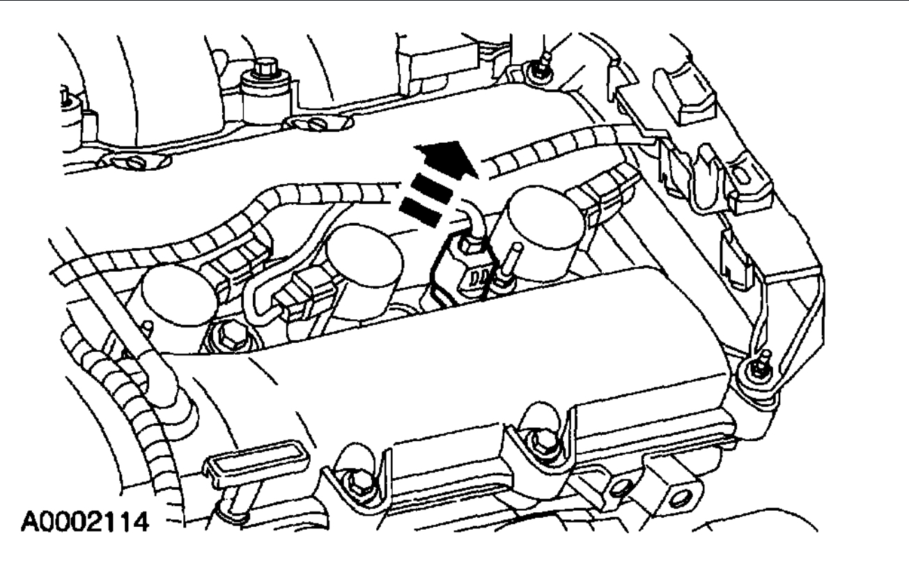
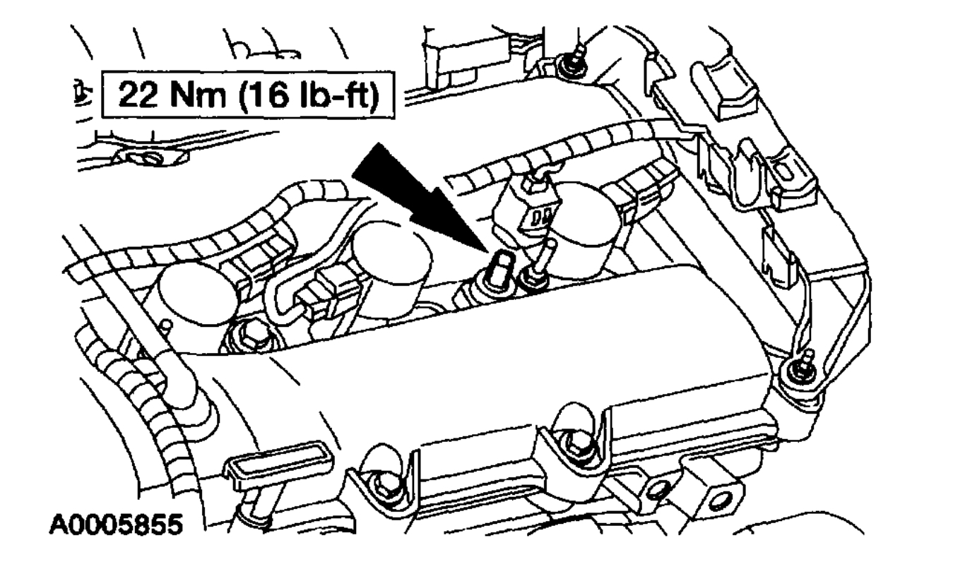
I also posted some pictures for you. Can you identify which componet has the failed hoses?
Roy
Exhaust Gas Recirculation Systems
Overview
The Exhaust Gas Recirculation (EGR) system controls the oxides of nitrogen (NOx) emissions. Small amounts of exhaust gases are recirculated back into the combustion chamber to mix with the air/fuel charge. The combustion chamber temperature is reduced, lowering NOx emissions.
Differential Pressure Feedback EGR System
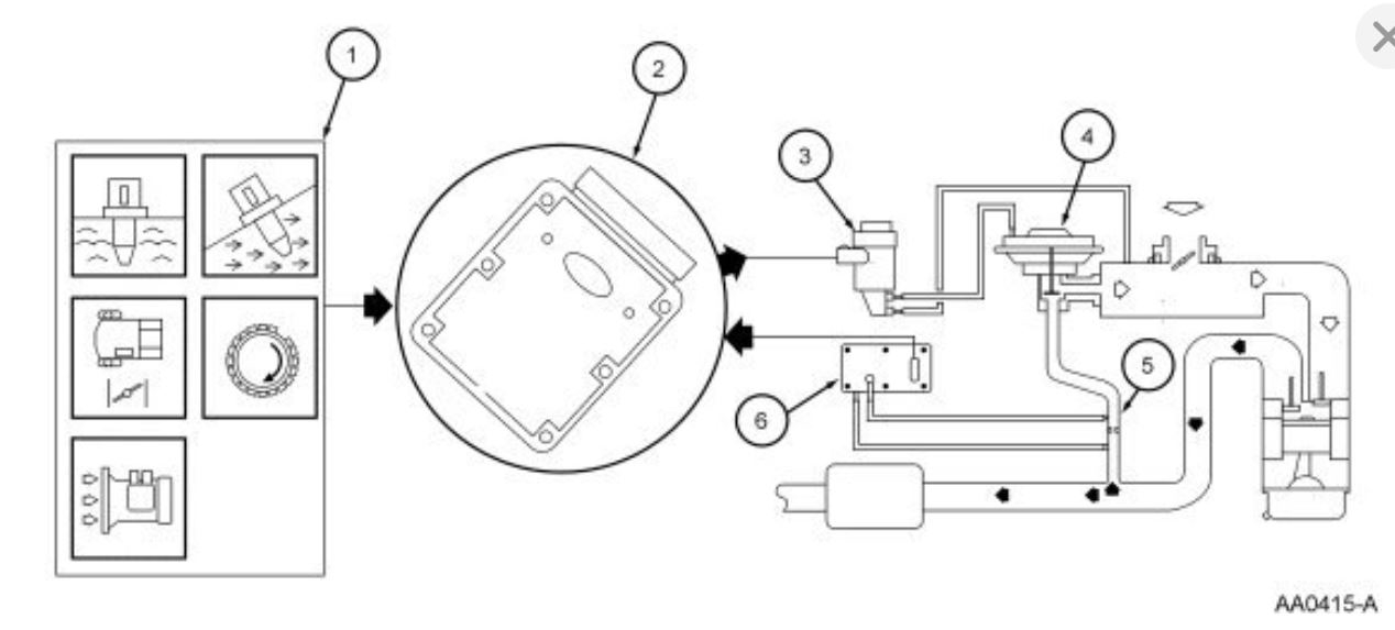
The Differential Pressure Feedback EGR system consists of a differential pressure feedback EGR sensor, EGR vacuum regulator solenoid, EGR valve, orifice tube assembly, powertrain control module (PCM) and connecting wires and vacuum hoses. Operation of the system is as follows (Figure 85):
1. Signals from the engine coolant temperature (ECT) sensor, intake air temperature (IAT) sensor, throttle position (TP) sensor, mass air flow (MAF) sensor and crankshaft position (CKP) sensor provide information on engine operating conditions to the PCM. The engine must be warm, stable and running at a moderate load and rpm before the EGR system is activated. The PCM deactivates EGR during idle, extended wide open throttle or whenever a failure is detected in an EGR component or EGR required input.
2. The PCM calculates the desired amount of EGR flow for a given engine condition. It then determines the desired pressure drop across the metering orifice required to achieve that flow and outputs the corresponding signal to the EGR vacuum regulator solenoid.
3. The EGR vacuum regulator solenoid receives a variable duty cycle signal (0 to 100%). The higher the duty cycle the more vacuum the solenoid diverts to the EGR valve.
4. The increase in vacuum acting on the EGR valve diaphragm overcomes the valve spring and begins to lift the EGR valve pintle off its seat, causing exhaust gas to flow into the intake manifold.
5. Exhaust gas flowing through the EGR valve must first pass through the EGR metering orifice. With one side of the orifice exposed to exhaust backpressure and the other to the intake manifold, a pressure drop is created across the orifice whenever there is EGR flow. When the EGR valve closes, there is no longer flow across the metering orifice and pressure on both sides of the orifice is the same. The PCM constantly targets a desired pressure drop across the metering orifice to achieve the desired EGR flow.
6. The differential pressure feedback EGR sensor measures the actual pressure drop across the metering orifice and relays a proportional voltage signal (0 to 5 volts) to the PCM. The PCM uses this feedback signal to correct for any errors in achieving the desired EGR flow.
imageOpen In New TabZoom/Print
Differential Pressure Feedback EGR System Operation (Refer to the On-Board Diagnostics II System Overview for icon definitions.)
Hardware
Differential Pressure Feedback EGR Sensor
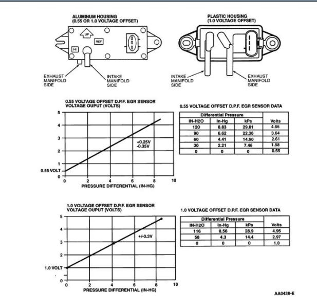
The differential pressure feedback EGR sensor (Figure 86) is a ceramic, capacitive-type pressure transducer that monitors the differential pressure across a metering orifice located in the orifice tube assembly. The differential pressure feedback sensor receives this signal through two hoses referred to as the downstream pressure hose (REF SIGNAL) and upstream pressure hose (HI SIGNAL). The HI and REF hose connections are marked on the aluminum differential pressure feedback EGR sensor housing for identification (note that the HI signal uses a larger diameter hose). The differential pressure feedback EGR sensor outputs a voltage proportional to the pressure drop across the metering orifice and supplies it to the PCM as EGR flow rate feedback.
imageOpen In New TabZoom/Print
Differential Pressure Feedback EGR Sensor
Tube Mounted Differential Pressure Feedback EGR Sensor
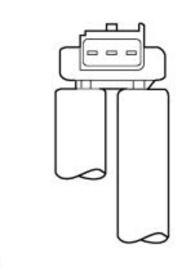
The tube mounted differential pressure feedback EGR sensor (Figure 87)is identical in operation as the larger metal or plastic DPFE sensors and uses a 1.0 volt offset. The HI and REF hose connections are marked on the underside of the sensor.
imageOpen In New TabZoom/Print
Tube Mounted Differential Pressure Feedback EGR Sensor
EGR Vacuum Regulator Solenoid
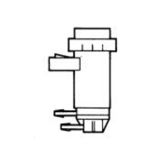
The EGR vacuum regulator solenoid (Figure 88) is an electromagnetic device which is used to regulate the vacuum supply to the EGR valve. The solenoid contains a coil which magnetically controls the position of a disc to regulate the vacuum. As the duty cycle to the coil increases, the vacuum signal passed through the solenoid to the EGR valve also increases. Vacuum not directed to the EGR valve is vented through the solenoid vent to atmosphere. Note that at 0% duty cycle (no electrical signal applied), the EGR vacuum regulator solenoid allows some vacuum to pass, but not enough to open the EGR valve.
imageOpen In New TabZoom/Print
EGR Vacuum Regulator Solenoid
Images (Click to enlarge)
Nov 19, 2020 at 3:28 AM