Welcome to 2carPros.
The component you replaced is the only thing responsible for the air temp entering the vehicle. I attached a picture of it to confirm you got the right one.
Now, are you sure there is power to the actuator? You mentioned it worked after you removed it. I just wondering if there is an issue with power to it.
Here are the directions for testing the system electronics. The attached picture will correlate with these directions so you know which pins on the connector to check. You will need a multi meter or volt meter and some general testing knowledge. Here are a few links you may find helpful:
https://www.2carpros.com/articles/how-to-use-a-test-light-circuit-tester
https://www.2carpros.com/articles/how-to-use-a-voltmeter
https://www.2carpros.com/articles/how-to-check-wiring
______________________________________________________
PINPOINT TEST O: THE TEMPERATURE CONTROL IS INOPERATIVE/DOES NOT OPERATE CORRECTLY - MANUAL CLIMATE CONTROL
Climate Control System
Pinpoint Tests
Pinpoint Test O: The Temperature Control is Inoperative/Does Not Operate Correctly - Manual Climate Control
Refer to Wiring Diagram Set 54, Manual Climate Control System for schematic and connector information. See: Vehicle > Electrical > Diagrams By Number
Normal Operation
Under normal operation, the temperature blend door actuator receives voltage and ground. As the temperature selection changes it varies the voltage to the temperature blend door actuator from the temperature selector.
This pinpoint test is intended to diagnose the following:
- Fuse
- Wiring, terminals or connectors
- Temperature control switch
- Temperature blend door actuator
- Stuck or bound linkage or door
PINPOINT TEST O: THE TEMPERATURE CONTROL IS INOPERATIVE/DOES NOT OPERATE CORRECTLY - MANUAL CLIMATE CONTROL
-------------------------------------------------
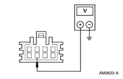
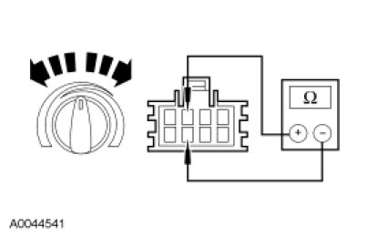
O1 CHECK THE VOLTAGE TO THE BLEND DOOR ACTUATOR
- Ignition OFF.
- Disconnect: Temperature Blend Door Actuator C2091.
- Ignition ON.
- Measure the voltage between ground and temperature blend door actuator C2091-7, circuit CBP20 (YE/VT), harness side.
pic 1
- Is the voltage greater than 10 volts?
Yes
GO to O2.
No
VERIFY Battery Junction Box (BJB) fuse 20 (10A) is OK. If OK, REPAIR circuit CBP20 (YE/VT) for an open. TEST the system for normal operation.
-------------------------------------------------
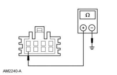
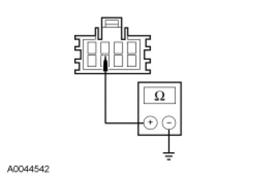
O2 CHECK CIRCUIT GD140 (BK/GN) FOR AN OPEN
- Ignition OFF.
- Measure the resistance between ground and temperature blend door actuator C2091-8, circuit GD140 (BK/GN), harness side.
pic 2
- Is the resistance less than 5 ohms?
Yes
GO to O3.
No
REPAIR circuit GD140 (BK/GN) for an open. TEST the system for normal operation.
-------------------------------------------------
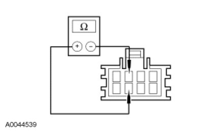
O3 CHECK THE TEMPERATURE CONTROL POTENTIOMETER TOTAL RESISTANCE
- Ignition OFF.
- Measure the resistance between temperature blend door actuator C2091-7, circuit CBP20 (YE/VT), harness side and C2091-3, circuit VH439 (GY/VT), harness side.
pic 3
- Is the resistance between 30 and 1,600 ohms?
Yes
GO to O6.
No
If the resistance is less than 30 ohms, GO to O4.
If the resistance is greater than 1,600 ohms, GO to O5.
-------------------------------------------------
O4 CHECK CIRCUITS CBP20 (YE/VT) AND VH439 (GY/VT) FOR A SHORT TOGETHER
- Disconnect: Climate Control Assembly C294C.
- Measure the resistance between temperature blend door actuator C2091-7, circuit CBP20 (YE/VT), harness side and C2091-3, circuit VH439 (GY/VT), harness side.
pic 4
- Is the resistance greater than 10,000 ohms?
Yes
INSTALL a new climate control assembly. TEST the system for normal operation.
No
REPAIR circuits CBP20 (YE/VT) and VH439 (GY/VT) for a short together. TEST the system for normal operation.
-------------------------------------------------
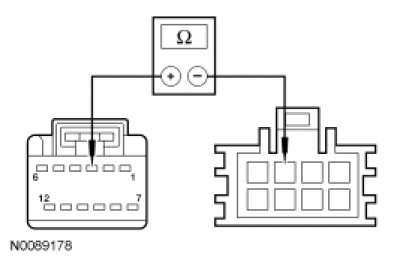
O5 CHECK VH439 (GY/VT) FOR AN OPEN
- Disconnect: Climate Control Assembly C294C.
- Measure the resistance between blend door actuator control connector C2091-3, circuit VH439 (GY/VT), harness side and climate control assembly C294C-3, circuit VH439 (GY/VT), harness side.
pic 5
- Is the resistance less than 5 ohms?
Yes
INSTALL a new climate control assembly. TEST the system for normal operation.
No
REPAIR circuit VH439 (GY/VT) for an open. TEST the system for normal operation.
-------------------------------------------------
O6 CHECK THE TEMPERATURE CONTROL POTENTIOMETER OPERATION
- Measure the resistance between temperature blend door actuator C2091-7, circuit CBP20 (YE/VT), harness side and C2091-3, circuit CH439 (GY/VT), harness side while rotating the temperature control potentiometer from full WARM to full COOL.
pic 6
- Does the resistance vary between 30 and 1,600 ohms?
Yes
GO to O7.
No
INSTALL a new climate control assembly. TEST the system for normal operation.
O7 CHECK CIRCUIT VH439 (GY/VT) FOR A SHORT TO GROUND
- Disconnect: Climate Control Assembly C294C.
- Measure the resistance between ground and blend door actuator C2091-3, circuit VH439 (GY/VT), harness side.
pic 7
- Is the resistance greater than 10,000 ohms?
Yes
GO to O8.
No
REPAIR circuit VH439 (GY/VT) for a short to ground. TEST the system for normal operation.
-------------------------------------------------
O8 CHECK FOR A BINDING, STUCK OR BROKEN BLEND DOOR
- Ignition OFF.
- Remove the actuator.
- Inspect for a binding, stuck or broken blend door or linkage.
- Is there a binding, stuck or broken blend door or linkage condition?
Yes
REPAIR the blend door/linkage. TEST the system for normal operation.
No
INSTALL a new temperature blend door actuator. TEST the system for normal operation.
+++++++++++++++++++++++++++++++++++++++++++++++++++++++++++++++++++++
Let me know if this helps or if you have other questions. Since the actuator is new and the door isn't stuck, it has to be an electrical issue to the actuator.
Take care,
Joe
Images (Click to enlarge)
May 18, 2019 at 9:25 PM