Hi,
It could be related to the crankshaft position sensor. When they start to fail, they are adversely affected by heat. Take a look through this link:
https://www.2carpros.com/articles/symptoms-of-a-bad-crankshaft-sensor
When the engine won't restart, check to see if there is spark to the plugs or using a live data scan tool, see if there is an RPM signal when trying to start it.
Here is a link that explains how to check for ignition spark:
https://www.2carpros.com/articles/how-to-test-an-ignition-system
If you find the sensor is bad, here is a link to help replace it:
https://www.2carpros.com/articles/symptoms-of-a-bad-crankshaft-sensor
Here are directions specific to your vehicle. The pics below correlate with the directions.
_________________________
2003 Pontiac Vibe L4-1.8L VIN 8
Crankshaft Position (CKP) Sensor Replacement
Vehicle Powertrain Management Sensors and Switches - Powertrain Management Sensors and Switches - Computers and Control Systems Crankshaft Position Sensor Service and Repair Procedures Crankshaft Position (CKP) Sensor Replacement
CRANKSHAFT POSITION (CKP) SENSOR REPLACEMENT
REMOVAL PROCEDURE
1. Raise and suitably support the vehicle. Refer to Vehicle Lifting.
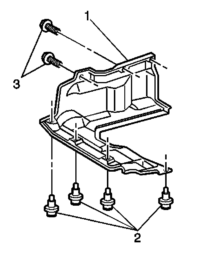
pic 1
2. Remove the two bolts (3) that secure the stone shield (1).
3. Remove the four retainers (2) and the stone shield (1).
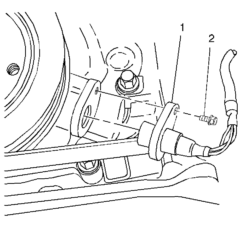
pic 2
4. Disconnect the CKP sensor electrical connector.
5. Remove the one hold down bolt (2).
6. Remove the CKP sensor (1) from the front cover of the engine block.
INSTALLATION PROCEDURE
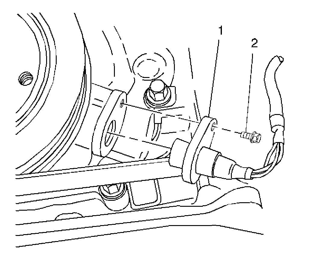
pic 3
1. Install the CKP sensor (1) into the front cover of the engine block.
2. Install the CKP sensor hold down bolt (2).
NOTE: Refer to Fastener Notice in Service Precautions.
Tighten
Tighten the hold down bolt to 9 N.m (80 lb in).
3. Connect the CKP sensor electrical connector.
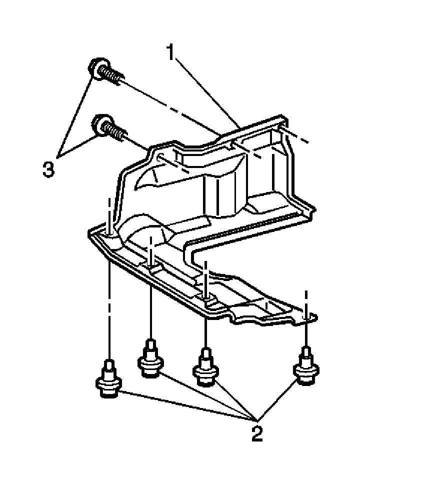
pic 4
4. Install the stone shield (1) with the four retainers (2).
Tighten
Tighten the two shield bolts to 10 N.m (89 lb in).
5. Secure the stone shield (1) with the two bolts (3).
6. Lower the vehicle
_________________________________________________________
As far as the camshaft sensor issue, here are the diagnostics for repairs. The remaining pics correlate with the directions.
________________________________________________________
2003 Pontiac Vibe L4-1.8L VIN 8
P0340
Vehicle ALL Diagnostic Trouble Codes ( DTC ) Testing and Inspection P Code Charts P0340
P0340
CIRCUIT DESCRIPTION
The DTC P0340 Camshaft Position (CMP) Sensor Circuit diagnostic monitors the signal from the camshaft position (CMP) sensor. The CMP sensor is a magnetic generator type sensor that produces an AC signal. The CMP sensor signal increases in frequency as the engine RPM increases. The camshaft position signal is used by the powertrain control module (PCM) to determine the optimum ignition timing and the optimum fuel delivery. The CMP sensor is also used to monitor engine misfire and monitor the operation of the CMP actuator system.
CONDITIONS FOR SETTING THE DTC
- No CMP sensor signal is sent to the PCM while cranking.
OR
- No CMP sensor signal is sent to the PCM with the engine speed at 600 RPM or more.
ACTION TAKEN WHEN THE DTC SETS
- The PCM illuminates the malfunction indicator lamp (MIL).
- The PCM stores the conditions which were present when the DTC set as Freeze Frame data.
CONDITIONS FOR CLEARING THE MIL/DTC
- The PCM turns OFF the MIL on the third consecutive trip cycle during which the diagnostic has been run and the fault condition is no longer present.
- The DTC clears after 40 consecutive warm-up cycles have occurred without a fault.
- A DTC can be cleared by using the scan tool Clear DTC Information function.
DIAGNOSTIC AIDS
Check for any of the following conditions:
- The camshaft position (CMP) sensor output may be affected by temperature. Inspect the sensors operation and internal resistance at various temperatures. The CMP sensor resistance when cold should be between 835-1,400 ohms at -10 to +50°C (14-122°F). The CMP sensor resistance when hot should be between 1,060-1,645 ohms at 50-100°C (122-212°F).
- The CMP sensor performance can be checked with a DMM and a scan tool. The AC voltage output of the CMP sensor, as measured with a DMM across the sensor electrical terminals, is approximately the same as engine speed. Run the engine at several different engine speeds and compare the numerical value on the scan tool with the numerical voltage reading on the DMM. If the reading of the DMM and the scan tool are not nearly equal, inspect for a faulty sensor or signal rotor.
- A DTC P0340 that sets while driving and checks OK may be caused by inadequate CMP sensor circuit shielding. Check that the CMP sensor circuit is properly shielded and that the drain wire is fastened securely to ground.
An intermittent malfunction may be caused by a fault in the CMP sensor electrical circuit. Inspect the wiring harness and the components for an intermittent condition. Refer to Intermittent Conditions. See: Computers and Control Systems > Initial Inspection and Diagnostic Overview > Intermittent Conditions
Repair any electrical circuit faults that were found.
The information included in the Freeze Frame data can be useful in determining the vehicle operating conditions when the DTC first set.
TEST DESCRIPTION
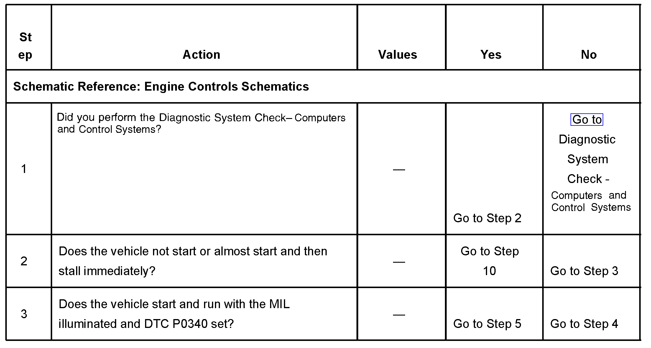
Steps 1-3
pic 5
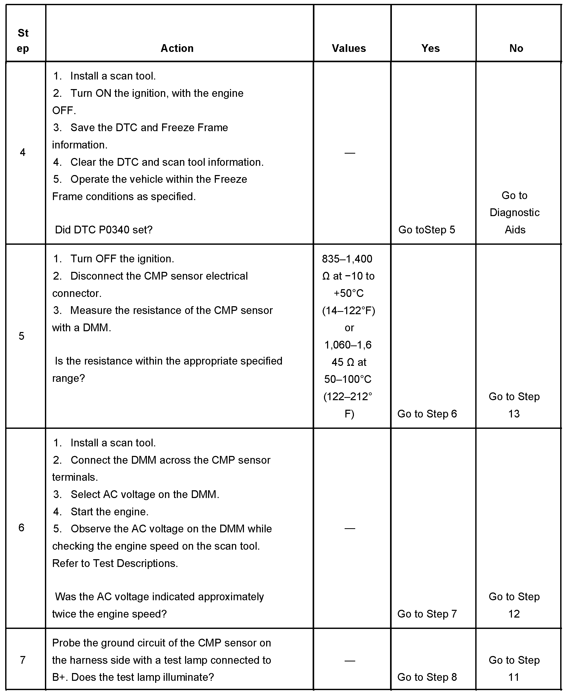
Steps 4-7
pic 6
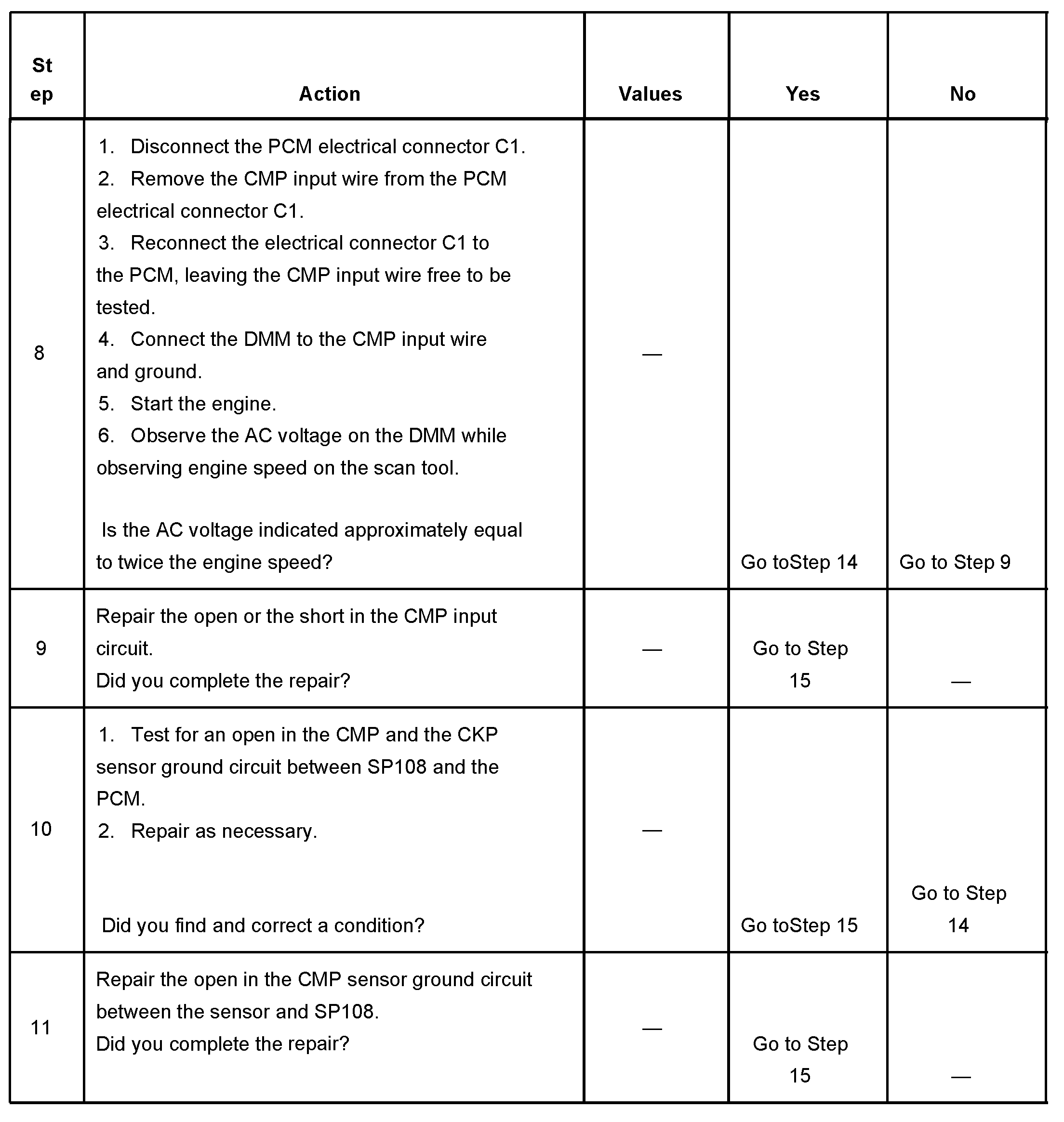
Steps 8-11
pic 7
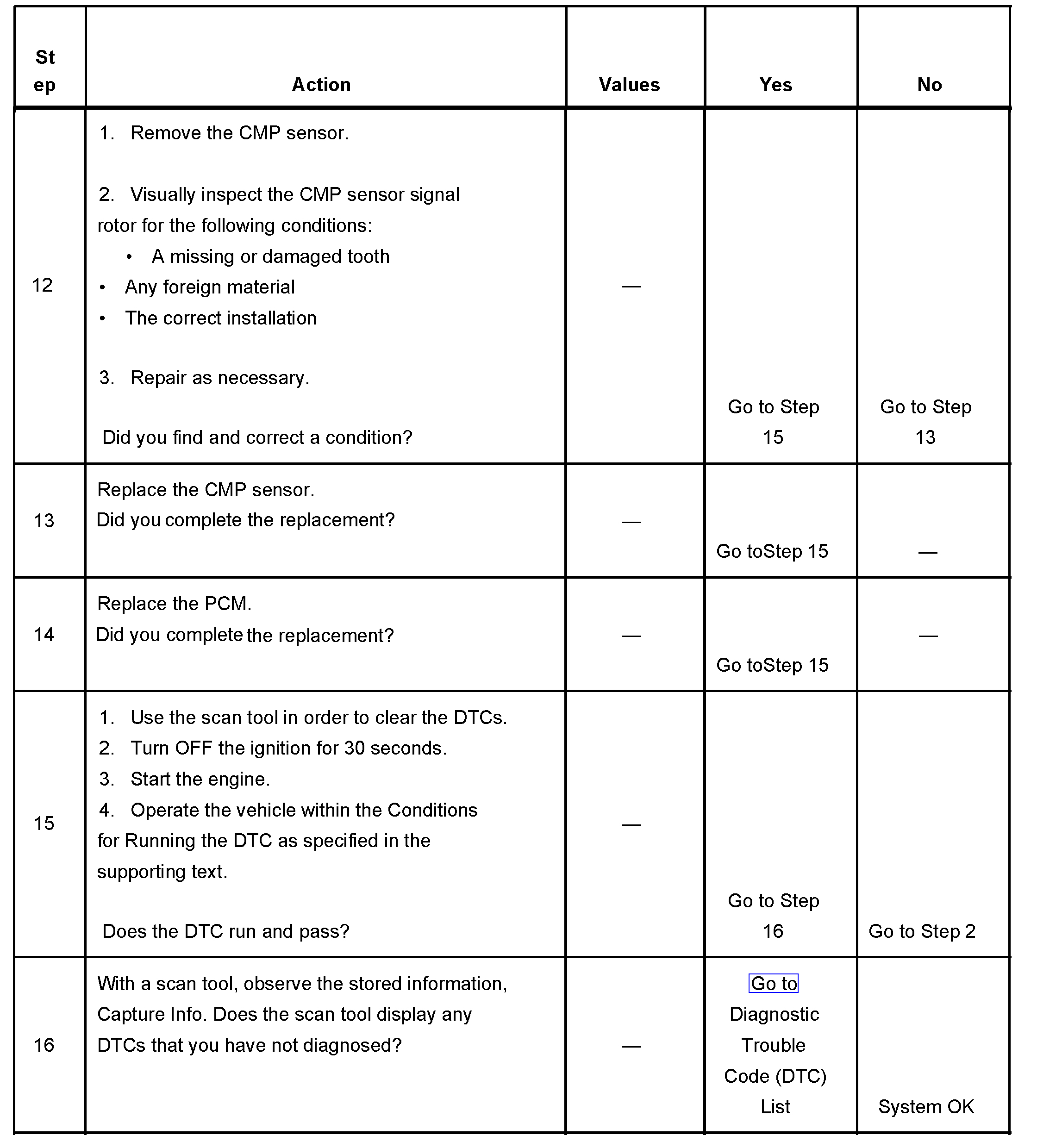
Steps 12-16
pic 8
The numbers below refer to the step numbers on the diagnostic table.
1. The Diagnostic System Check-Computers and Controls Systems prompts the technician to complete some basic checks and store the Freeze Frame data on the scan tool if applicable. This creates an electronic copy of the data taken when the fault occurred. The information is then stored in the scan tool for later reference.
2. This step tests for an open in the ground circuit of the CMP sensor from PCM connector C 1 terminal 34 to SP108. The engine will not stay running and DTC P0340 will set if the CMP sensor and CKP sensor ground circuit is open.
3. This step determines if DTC P0340 is the result of a hard failure or an intermittent condition.
5. This step verifies the internal resistance of the camshaft position sensor. A typical value at 23°C (74°F) is 1.1k ohms.
6. This step verifies the CMP sensor output signal. The CMP sensor sends the PCM one electrical pulse for every revolution of the intake camshaft. Therefore the AC signal generated by the CMP sensor will be numerically analogous to the engine speed. With the engine speed at about 1,200 RPM, the CMP sensor voltage should be around 2.450-2.550 volts AC.
8. This step tests the camshaft position (CMP) sensor input circuit to the PCM. The AC signal generated by the CMP sensor will be numerically analogous to the engine speed. With the engine speed at about 1,200 RPM, the CMP sensor voltage should be around 2.450-2.550 volts AC. The CMP sensor signal wire must be removed from the PCM connector in order to accurately check the sensor output. If the CMP sensor signal wire is backprobed while connected to the PCM, the AC voltage indicated on a DMM will be approximately 15-20 percent lower than the actual engine speed.
12. This step inspects for a faulty signal rotor on the camshaft. Visually inspect the tooth of the signal rotor through the CMP sensor aperture for damage, foreign material, and installation.
_________________________________________
I hope this helps. Let me know if you have other questions.
Take care and God Bless,
Joe
Images (Click to enlarge)
Mar 2, 2021 at 8:53 PM