Hi,
The O2 sensor won't prevent it from starting. As far as the brake light, make sure the brake fluid isn't low. For now, lets get it running and then focus on the other two things.
First, I need to know if the engine is getting spark and fuel. Here are three links. First discusses the most common causes of a crank no start. The second two show how to test for fuel pressure and for ignition spark.
________________________________
https://www.2carpros.com/articles/car-cranks-but-wont-start
https://www.2carpros.com/articles/how-to-check-fuel-system-pressure-and-regulator
https://www.2carpros.com/articles/how-to-test-an-ignition-system
________________________________
Here are the directions for testing fuel pressure specific to your vehicle. Pressure specs are included in the directions. The attached pictures correlate with the directions. These directions require specific tooling.
_______________________________
2008 Mitsubishi Truck Endeavor AWD V6-3.8L (6G75)
Component Tests and General Diagnostics
Vehicle Powertrain Management Fuel Delivery and Air Induction Fuel Pump Fuel Pressure Testing and Inspection Component Tests and General Diagnostics
COMPONENT TESTS AND GENERAL DIAGNOSTICS
The content of this article and images reflects the changes identified in TSB - 10-13-008.
FUEL PRESSURE TEST
Required Special Tools:
- MB991958: Scan tool (M.U.T.-III Sub Assembly)
- MB991824: V.C.I.
- MB991827: USB Cable
- MB991910: Main Harness A
- MB991981: Fuel Pressure Gauge Set
- MB992001: Hose Adaptor
- MB992049: Quick Connector
- MB992076: Injector Test Set
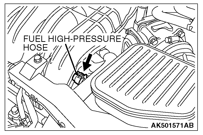
1. Release residual pressure from the fuel line to prevent fuel spray.
WARNING: To prevent a fire, cover the hose connection with shop towels to prevent splashing of fuel that could be caused by some residual pressure in the fuel pipe line.
pic 1
2. Disconnect the fuel high-pressure hose at the fuel rail side.
3. Assemble the special tool MD998707 of special tool as shown in figure.
NOTE: The special tool MB992076 (injector test set) is compatible with the special tool MB998706 (injector test set).
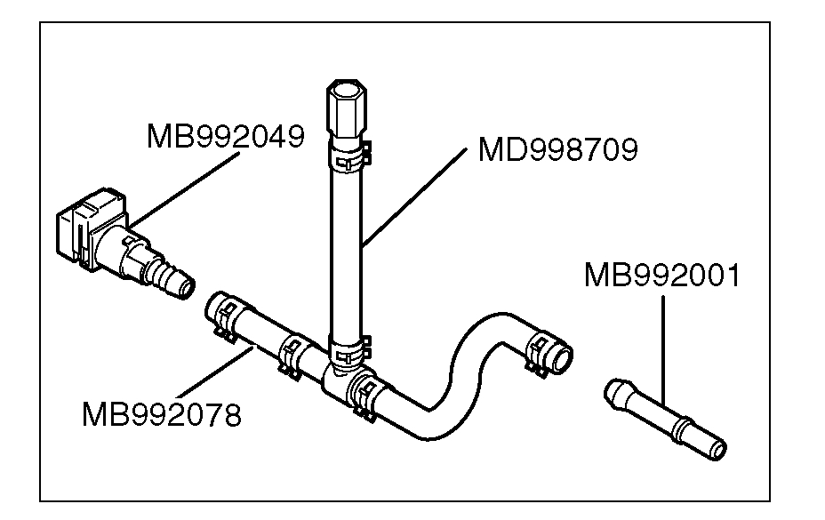
In case of vehicle using (square) quick connector
W/ Square Quick Connector
pic 2
(1) Remove the injector installation adapter from the hose. Remove another hose together with the adapter and remove the adapter from the remaining hose.
(2) Install the special tool MB992049 (quick connector) and the special tool MB992001 (hose adapter) to the hose without the adapter.
(3) Remove the nipple of the bolt of the special tool MD998709 (hose adapter).
(4) Install the special tool prepared in the procedure (3) to the nipple that was removed together with hose in the procedure (1).
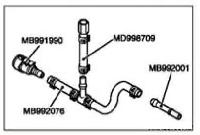
In case of vehicle using (round) quick connector
W/ Round Quick Connector
pic 3
(1) Remove the injector installation adapter from the hose. Remove another hose together with the adapter and remove the adapter from the remaining hose.
(2) Install the special tool MB991990 (quick connector) and the special tool MB992001 (hose adapter) to the hose without the adapter.
(3) Remove the nipple of the bolt of the special tool MD998709 (hose adapter).
(4) Install the special tool prepared in the procedure (3) to the nipple that was removed together with hose in the procedure (1).
4. Install the special tool assembled in step 3 between the fuel rail and the fuel high-pressure hose.
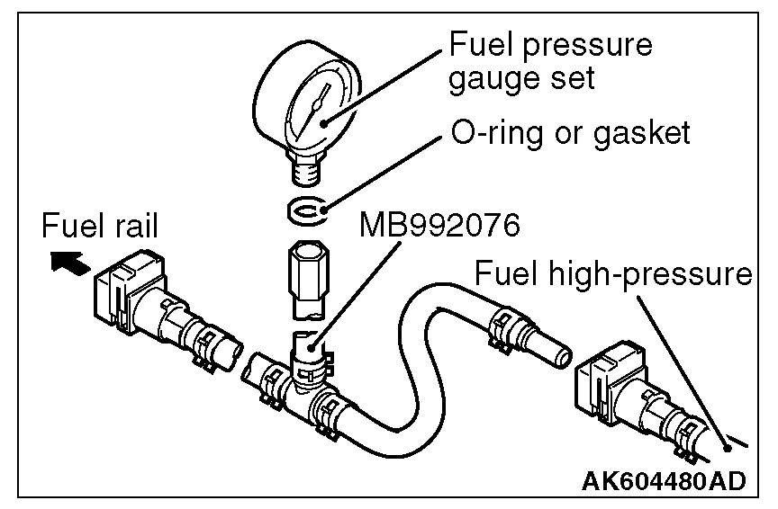
[When using the fuel pressure gauge]
pic 4
1. Via a suitable O-ring or gasket, install the fuel pressure gauge to the special tool that has already assembled as described.
2. Install the assembled fuel pressure measurement tools between the fuel rail and fuel high-pressure hose.
pic 5
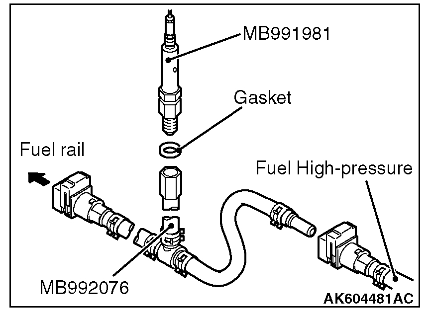
[When using special tool MB991981 (fuel pressure gauge set)]
1. Via a gasket, install the special tool MB991981 (fuel pressure gauge set) into the special tool that has already assembled as described.
2. Install the assembled fuel pressure measurement tools between the fuel rail and fuel high-pressure hose.
pic 6
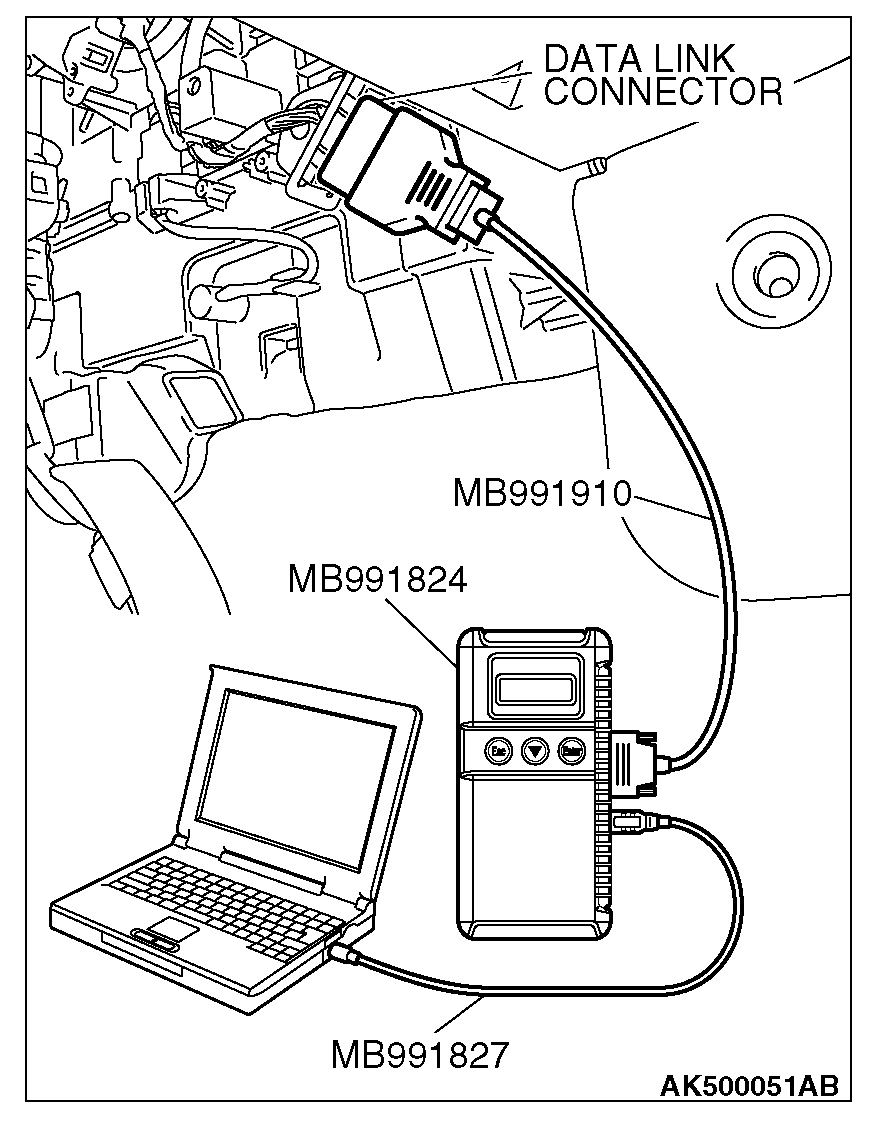
CAUTION: To prevent damage to scan tool MB991958, always turn the ignition switch to the "LOCK" (OFF) position before connecting or disconnecting scan tool MB991958.
7. Connect scan tool MB991958 to the data link connector.
8. Use Actuator test 9 to drive the fuel pump. Check that there is no fuel leaking from any section when the fuel pump is operating.
9. Stop the fuel pump.
10. Start the engine and run at idle.
11. Measure fuel pressure while the engine is running at idle.
Standard value: Approximately 324 kPa (47 psi) at curb idle
12. Check to see that fuel pressure at idle does not drop even after the engine has been revved several times.
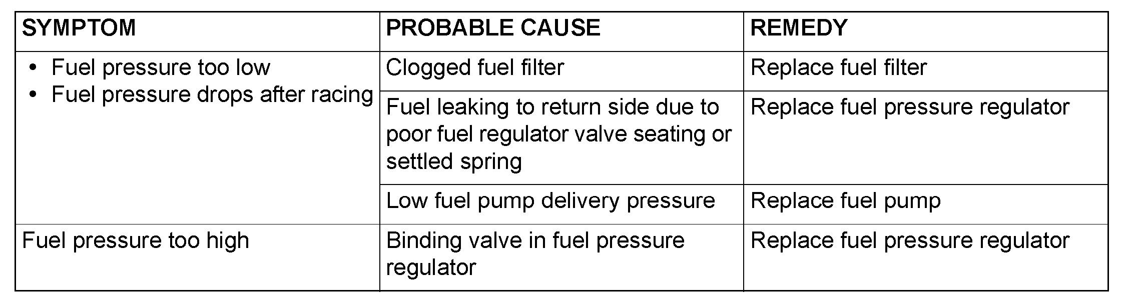
13. If any of fuel pressure measured in steps 11 to 12 is out of specification, troubleshoot and repair according to the table below.
pic 7
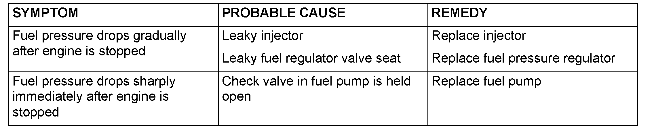
14. Stop the engine and observe fuel pressure gauge reading. It is normal if the reading does not drop within two minutes. If it does, observe the rate of drop and troubleshoot and repair according to the table below. Start, then stop the engine.
1. Squeeze the fuel supply line closed to confirm leak-down occurs from defective fuel pump check valve.
2. If pressure continues to drop with both fuel lines squeezed closed, injector(s) are leaking.
pic 8
15. Release residual pressure from the fuel pipe line.
WARNING: Cover the hose connection with shop towels to prevent splash of fuel that could be caused by some residual pressure in the fuel pipe line.
16. Remove the fuel pressure gauge and special tool from the fuel rail.
17. Fit the fuel high-pressure hose to the fuel rail.
18. Check for fuel leaks.
1. Use scan tool MB991958 to operate the fuel pump.
2. Check the fuel line for leaks and repair as needed.
19. Disconnect scan tool MB991958.
__________________________
If you are unable to perform these tests, see if the engine starts for a couple seconds using starting fluid. If it does and then stalls, we know it is a fuel related issue.
Let me know what you find.
Joe
Images (Click to enlarge)
Mar 1, 2020 at 7:50 PM