Welcome back, Patricia:
I have to be honest, it sounds like a bad crankshaft position sensor or the engine temp sensor. Both are not expensive and easy to install. I am going to provide the directions for you to install them. Please keep in mind, this is an educated guess based on past experience, but you may want to try it. Chances are it will be a lot cheaper than having the shop check it again with no response. First, take a look at this link:
https://www.2carpros.com/articles/symptoms-of-a-bad-crankshaft-sensor
Here is a link that shows in general how one is replaced.
https://www.2carpros.com/articles/crankshaft-angle-sensor-replacement
_______________________________
Here are directions specific to your vehicle for replacement. The pics attached correlate with the directions.
CRANKSHAFT POSITION (CKP) SENSOR REPLACEMENT
REMOVAL PROCEDURE
IMPORTANT: The CKP System Variation Learning Procedure will need to be performed whenever the Crankshaft Position (CKP) sensor is removed or replaced. Refer to CKP System Variation Learn Procedure.
CAUTION: Refer to Battery Disconnect Caution in Service Precautions.
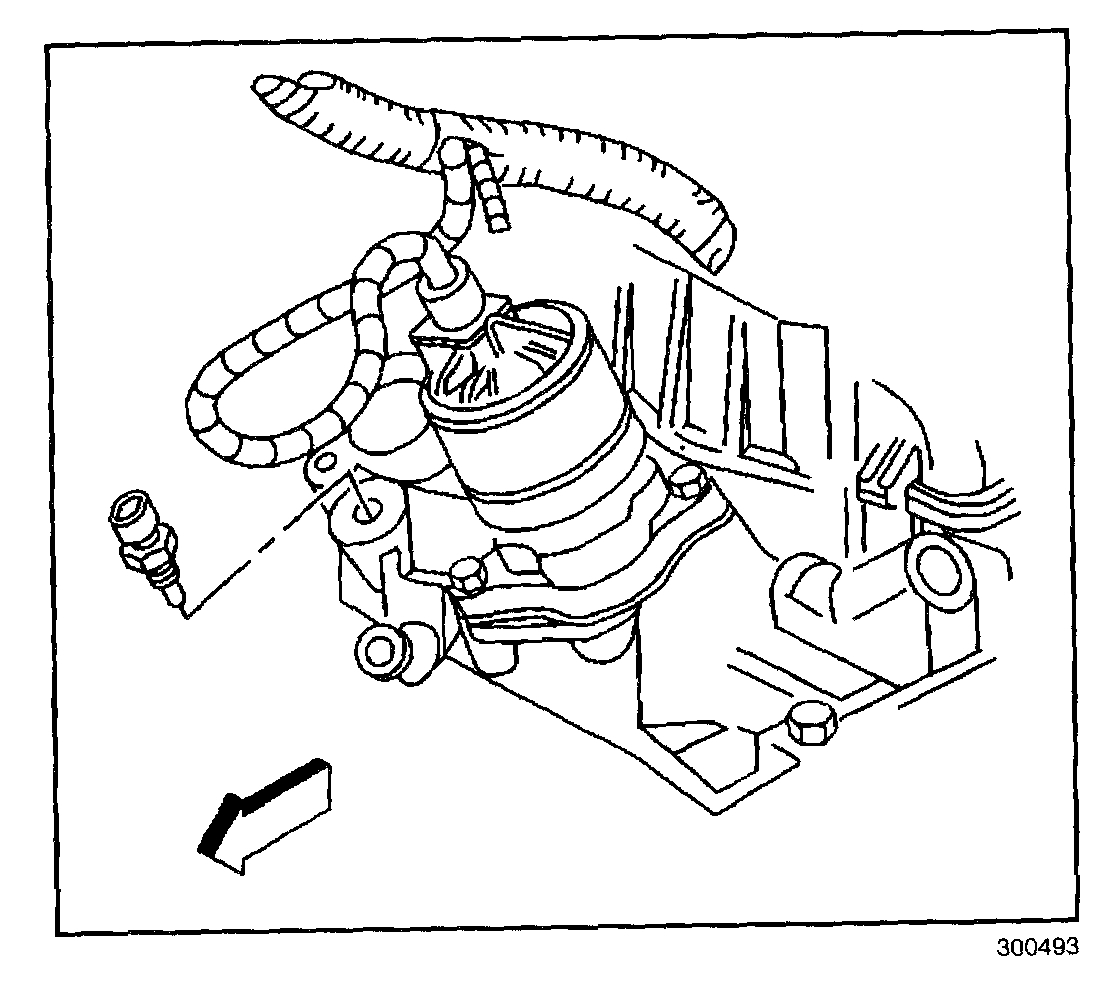
pic 1
1. Disconnect the negative battery cable.
2. Raise the vehicle. Refer to Lifting and Jacking the Vehicle
3. Remove the CKP sensor harness connector.
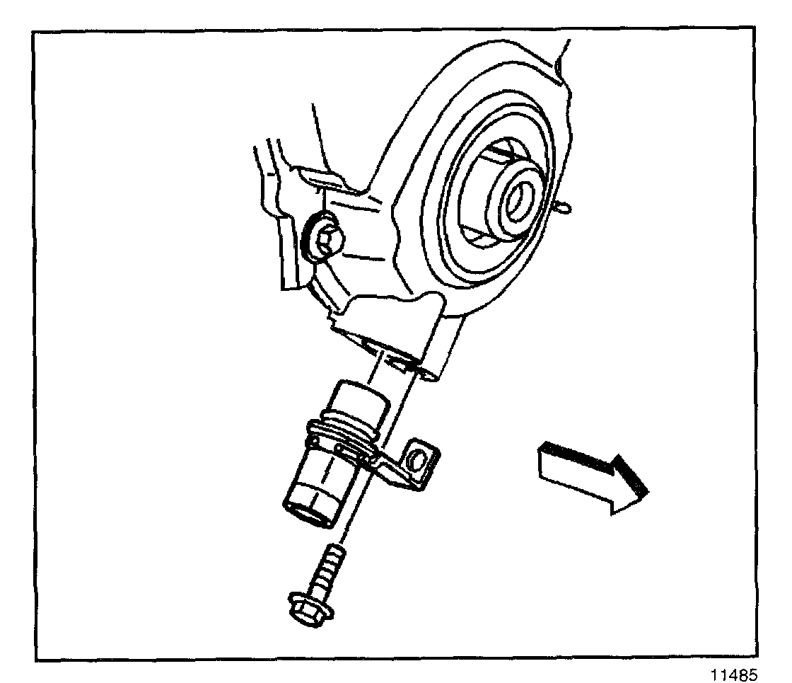
pic 2
4. Remove the sensor hold down bolt.
5. Remove the sensor from the timing cover.
INSTALLATION PROCEDURE
IMPORTANT: Make certain that the Crankshaft Position (CKP) sensor mounting surfaces are clean and free of burrs before installing the CKP sensor.
When installing a CKP sensor make sure the sensor is fully seated and held stationary in the front cover before torquing the hold down bolt into the front cover. A sensor which is not seated may result in erratic operation and lead to the setting of false codes.
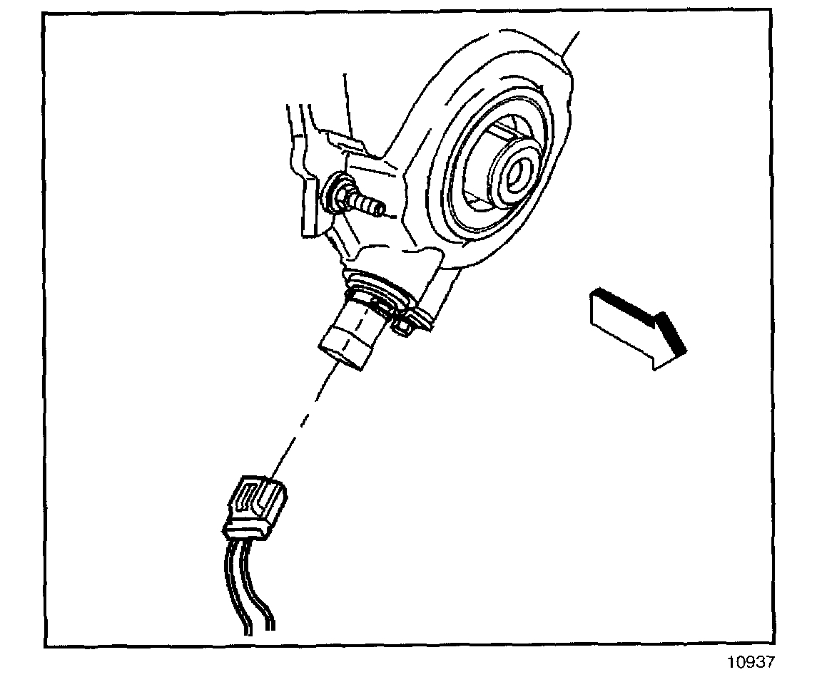
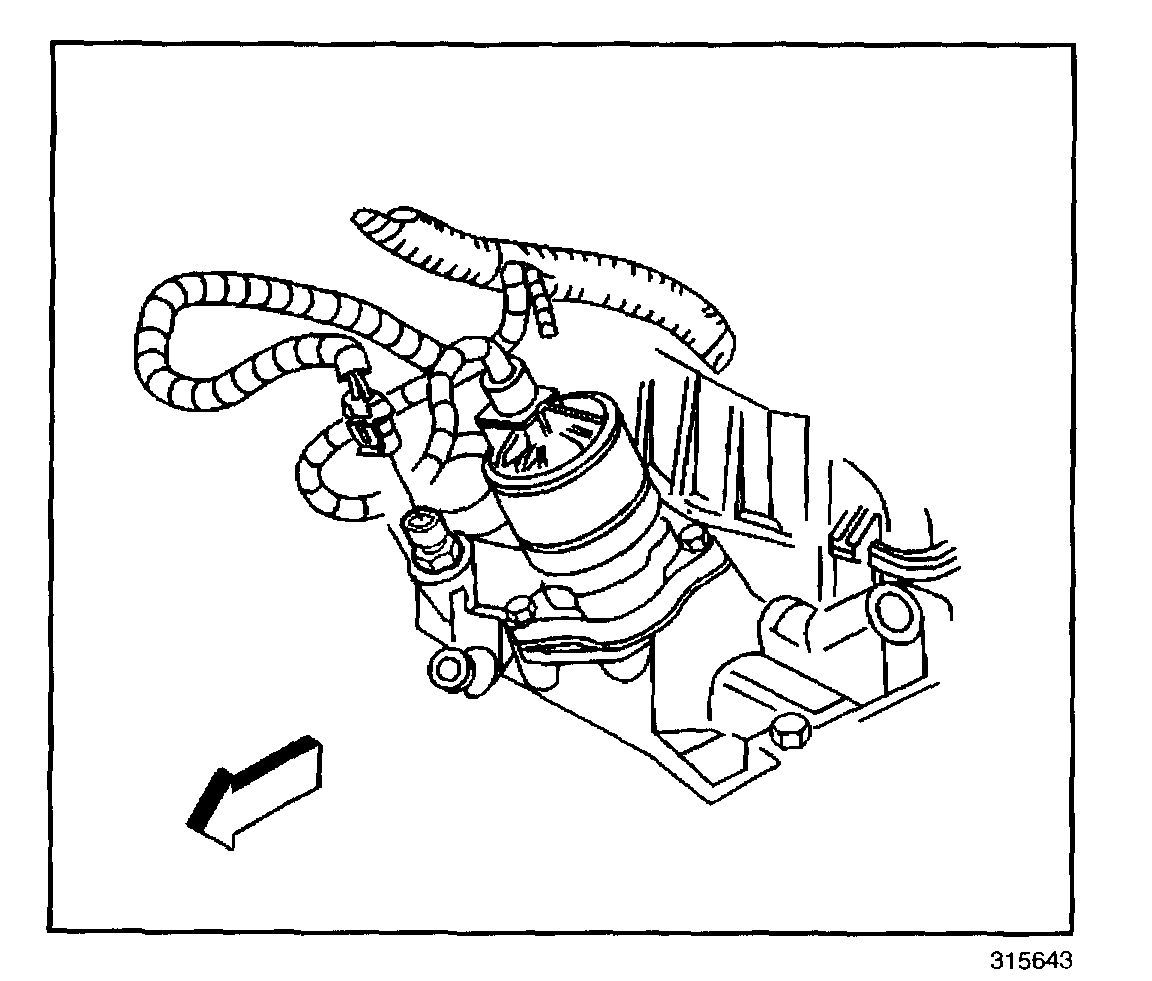
pic 3
1. Install the sensor into the timing cover. Lubricate the O-ring with clean engine oil before installing.
NOTE: Refer to Fastener Notice in Service Precautions.
2. Install the sensor hold down bolt.
Tighten
Tighten the bolt to 8 N.m (71 lb in).
pic 4
3. Install the CKP sensor harness connector.
4. Lower the vehicle. Refer to Lifting and Jacking the Vehicle.
5. Connect the negative battery cable.
6. Perform the CKP System Variation Learn Procedure. Refer to CKP System Variation Learn Procedure. See: Vehicle > Programming
____________________________
Variation relearn programming.
CRANKSHAFT POSITION (CKP) - VARIATION LEARN PROCEDURE
1. Connect the scan tool.
2. Apply the vehicles parking brake.
3. Block the drive wheels.
4. Close the hood.
5. Place the vehicles transmission in Park (A/T) or Neutral (M/T).
6. Idle the engine until the coolant temperature reaches 65°C (150°F).
7. Turn OFF all the accessories.
IMPORTANT: If the CKP System Variation Learn Procedure cannot be completed successfully, refer to DTC P1336 for additional diagnostic information.
8. Enable the Crankshaft Position System Variation Learn Procedure with the scan tool.
IMPORTANT: After the ignition switch is turned to the CRANK position, the Powertrain Control Module (PCM) must see a change in the state of brake switch (Released to Applied) to run the learn procedure. Also, the service brakes, not the parking brake, must be held throughout the duration of the learn procedure.
9. Apply and hold the service brakes.
IMPORTANT: While the learn procedure is in progress, release the throttle immediately when the engine starts to decelerate. The engine control is returned to the operator and the engine will respond to throttle position after the learn procedure is complete.
10. Slowly raise the engine speed to 4,000 RPM.
11. Immediately release the throttle when the engine speed decreases.
12. Turn OFF the ignition for 15 seconds after the learn procedure is completed successfully.
__________________________________________
Engine coolant temp sensor
https://www.2carpros.com/articles/coolant-temperature-sensor-cts-replacement
_________________________________________
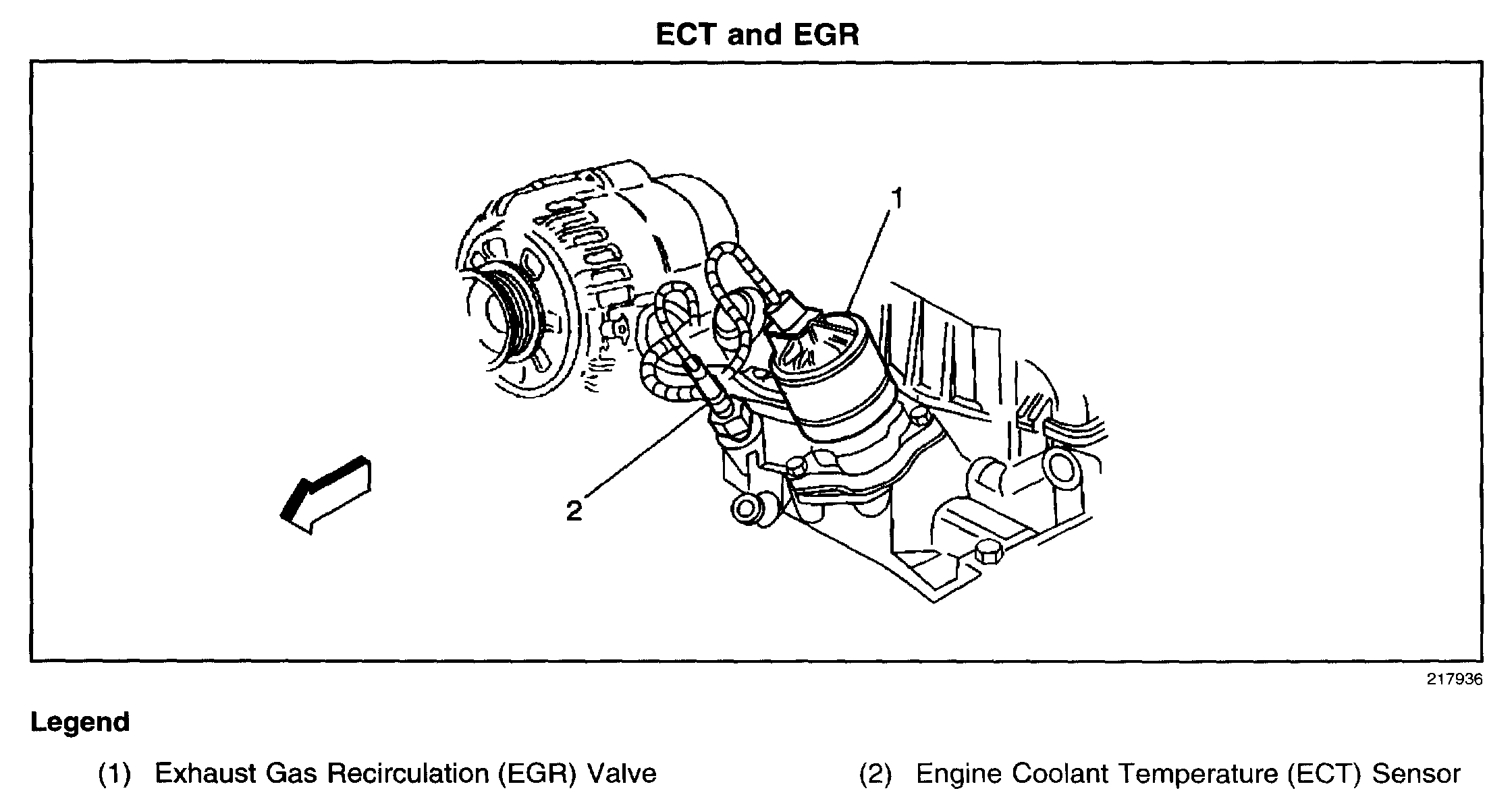
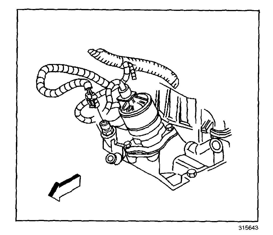
Pic 5 shows location.
Specific directions for your vehicle.
ENGINE COOLANT TEMPERATURE (ECT) SENSOR REPLACEMENT
REMOVAL PROCEDURE
NOTE: Use care when handling the coolant sensor. Damage to the coolant sensor will affect the operation of the fuel control system.
pic 6
1. Turn OFF the ignition.
2. Remove the air cleaner assembly.
3. Drain the cooling system below the level of the Engine Coolant Temperature (ECT) sensor. Refer to Draining and Filling Cooling System in Cooling System.
4. Disconnect the ECT sensor harness connector.
pic 7
5. Remove the ECT sensor.
INSTALLATION PROCEDURE
NOTE:
Replacement components must be the correct part number for the application. Components requiring the use of the thread locking compound, lubricants, corrosion inhibitors, or sealants are identified in the service procedure. Some replacement components may come with these coatings already applied. Do not use these coatings on components unless specified. These coatings can affect the final torque, which may affect the operation of the component. Use the correct torque specification when installing components in order to avoid damage.
Use care when handling the coolant sensor. Damage to the coolant sensor will affect the operation of the fuel control system.
pic 8
1. Coat the threads (only) with sealer GM P/N 9985253 or equivalent.
NOTE: Refer to Fastener Notice in Service Precautions.
2. Install the ECT sensor.
Tighten
Tighten the ECT sensor to 13 N.m (115 lb in).
pic 9
3. Connect the ECT sensor harness connector.
4. Refill the cooling system. Refer to Draining and Filling Cooling System in Cooling System.
5. Install the air cleaner assembly.
____________________________________________
If you do this, let me know the results or if you have other questions, let me know.
Take care,
Joe
Images (Click to make bigger)
Tuesday, May 14th, 2019 AT 6:33 PM