Code U010, crank no start?

Tiny
COPQERHEAD
  • MEMBER
  • 2003 HONDA ACCORD
  • 3.0L
  • V6
  • 2WD
  • AUTOMATIC
  • 243,000 MILES
Okay, so this problem all started because I was having battery issues. My battery kept draining, so I got it tested, came out to be bad, then replaced it. Installed the new battery, but when I went to start it something popped and wouldn't start. However, I was able to get it started with a jump box, just to get home and once home it hasn't started since. Checked the ODBII scan and it came back with 02 sensor code and the U0107 code. Now it seems that there is no spark from the plugs also. I've checked and replaced any fuses which were blown and the only one I found blown was for the ac compressor. I replaced the starter, also got that tested afterwards just to make sure it wasn't the problem. Replaced the Spark plugs and Coils. Still no spark. Took it to a shop and they replaced the Crank position sensor. The shop couldn't figure out the problem either on why it won't start. Oh, and once I got the car back from the shop, Now my key gets stuck in the ignition, and I have to disconnect the battery to release it. So yeah, one problem has created a new one, and I just want to get it started. Fuel pump was tested and is also working.
Friday, May 12th, 2023 AT 5:41 AM

3 Replies

Tiny
AL514
  • MECHANIC
  • 4,146 POSTS
Hello, sounds like the shop may have moved the wiring harness around, and made the issue worse because of the key issue. Which 02 sensor code was it? And do you have a Check Engine light on with just the key on (run position) engine off? It's most likely going to be a wiring issue with so many things happening at once, I will pull up the wiring diagrams for you and we can see why the Compressor fuse popped. As well as why there is lost communications with the TAC.(Throttle Actuator control module)
Verify the connector on the throttle body is tight and there are no pins inside the connector that are pushed back or spread pins.
For the AC compressor was it (Fuse 12 7.5amp) or (Fuse 30 7.5amp) that was blown?
Also, which sub model is this, DX, LX, EX, EX-L?

Before we get into everything, let's check this Ground (G101) location real quick. It's under the throttle body (marked in green) bolted right above that coolant hose. If you have a 12v test light, hook it to battery Positive and touch that G101 bolt and see if the test light is bright. Thats the Ground for the TAC module.
I would also unplug the A/C compressor for now and replace the fuse.
And just so you have this info, there is a Recall on the Ignition Interlock (3rd diagram).
Was this
answer
helpful?
Yes
No
Friday, May 12th, 2023 AT 11:43 AM
Tiny
COPQERHEAD
  • MEMBER
  • 2 POSTS
Okay sorry about the long wait for a response. But I believe it’s the ex version, sunroof, power windows and leather seats with faux wood panels. So I’ve tried testing the ground and the light does come up green once I touch the bolt. Do you think it could be an ecu problem? I have a similar Honda accord, a 2004 sedan version and I tested a theory about the ecu that if you leave the key in the on position (car off) the check engine light, I think it is will turn off after about 40 seconds if it has a reading from the ecu. But the 2004 does that, but my 03 doesn’t. So I was questioning that part also.
Was this
answer
helpful?
Yes
No
Friday, May 26th, 2023 AT 6:23 AM
Tiny
AL514
  • MECHANIC
  • 4,146 POSTS
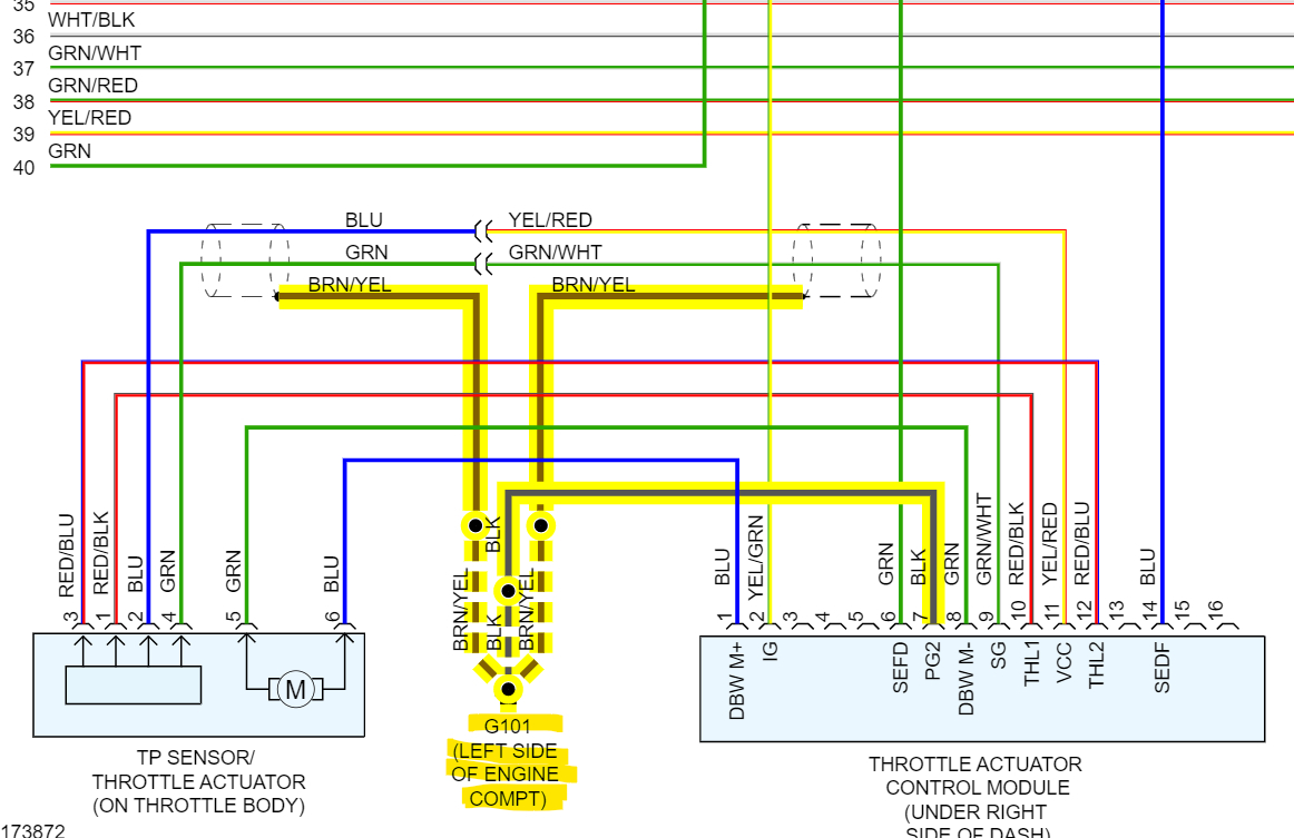
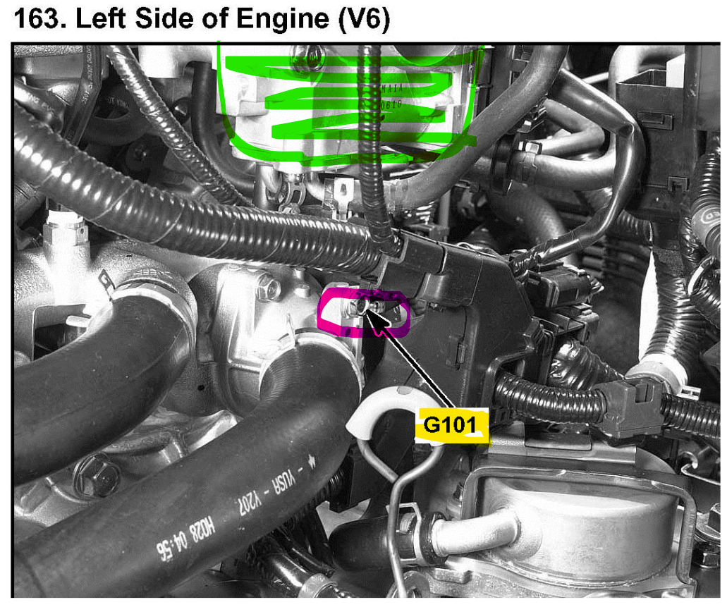
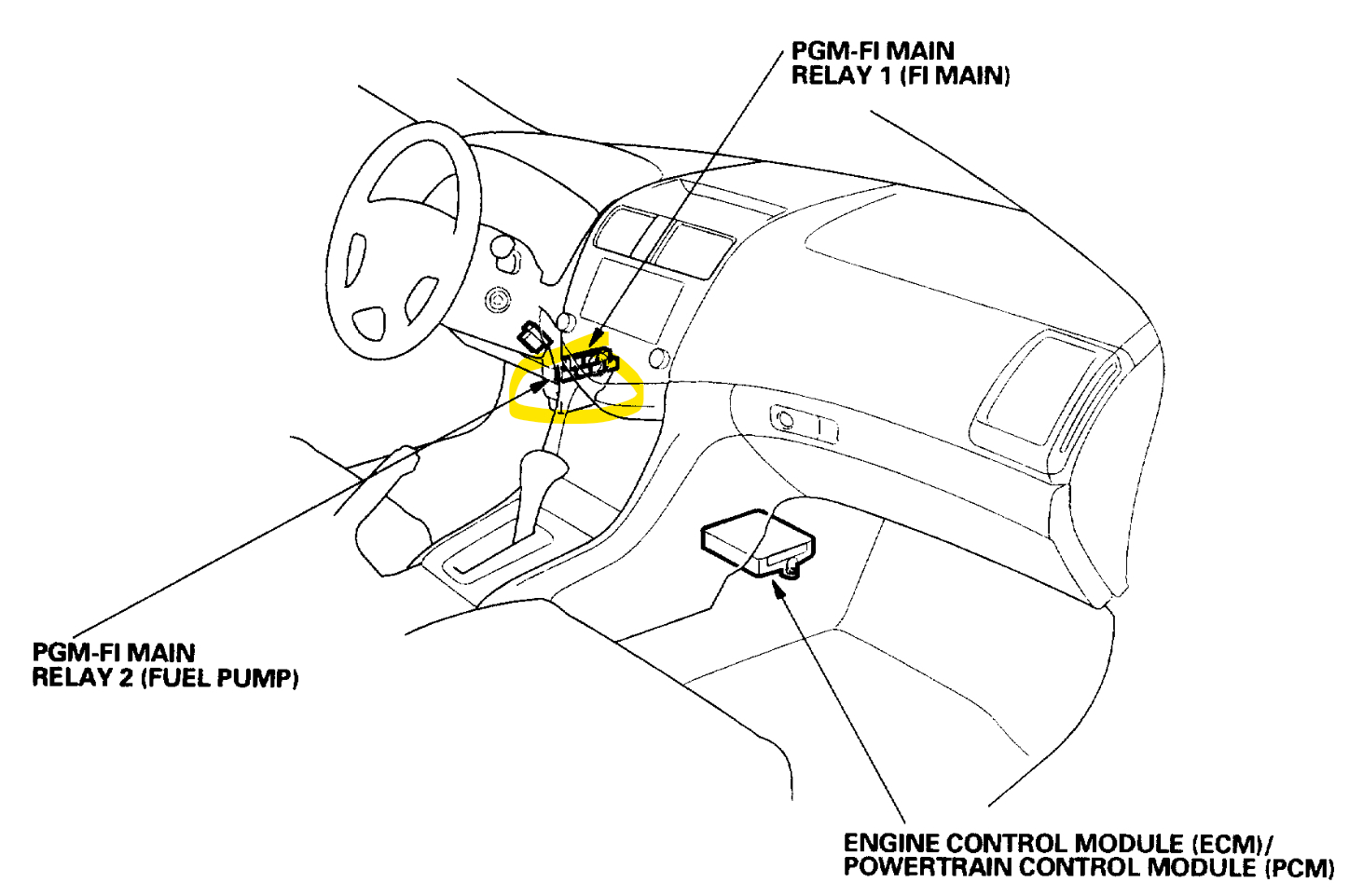
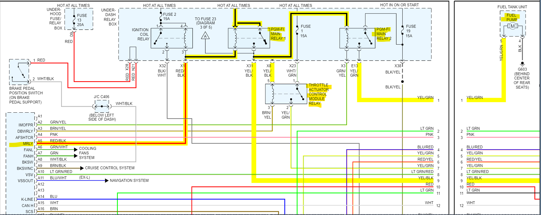
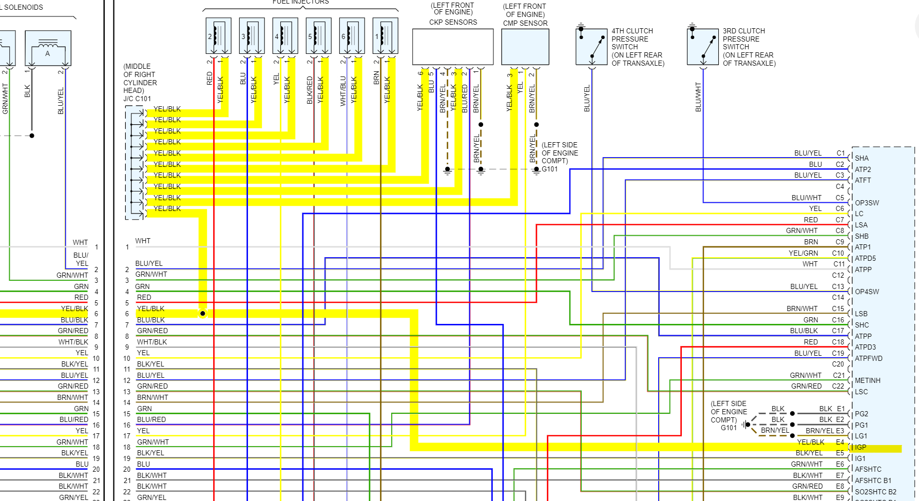
Hello, okay, I had to go over your case again since it's been a couple weeks or so. The Check engine light test you mentioned is a good clue. You are correct, when you turn the key to the on position, engine off, the check engine light should come on for a few seconds. If it doesn't that means that the ECM is either partially or fully not being powered up. It doesn't necessarily mean the ECM has failed, it just means for now, we know that it's not powering up. The Honda main relays are known for going bad, especially the earlier 2000s models. The fact that you were able to pull a code out of the ECM means that it was able to communicate with the scan tool. That tells me that at least part of the ECM was powered up enough to communicate on the data bus to your scan tool. I would be curious to see if you can read any live data with your scan tool, depending on the type of scanner you have. I will pull up some wiring diagrams and the location of the ECM so you can check it for power. It looks like from your folder I had pulled out the flow chart for diagnosing the Throttle control unit, which was for the U0107, but now that the check engine light is not coming on, the code is probably a result of the ECM being down and not the cause. And actually, looking at the ECM diagrams, the Throttle Actuator Control module relay is directly powered up by the PGM FI main relay 1. Thats one of the relays that seems to fail often in these vehicles. I remember replacing many of them back then. It's a large double relay up under the driver's side dash. It should have 2 connectors to it. Do you know if the shop it was at had tried replacing this relay, was there anything on the repair order about having changed it out? The PGM FI relay 1 powers up part of the ECM, the fuel injectors and a junction port that supplies power to a bunch of other components, the PGM FI 2 relay powers up the fuel pump. And I'll post diagrams of all these for you to see.

You can see by the diagrams 2 and 3 how much these relays are responsible for. And it might have been that part of the ECM was powered up, just not the entire module. Both the PGM FI relays are one unit. It's pretty easy to find, it will be up to the left of where your left foot is.

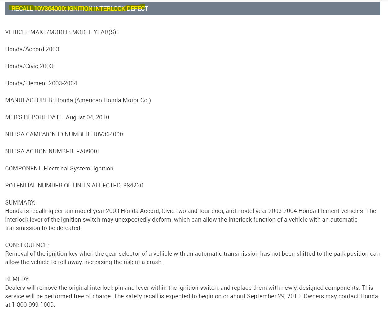
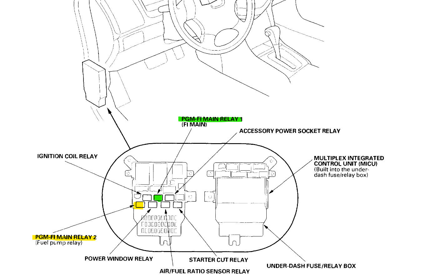
Ok it looks like they are located in this multiplex fuse relay box (diagram 4). In the older vehicles they were separated and just bolted to the body of the car. So, with the key Off, I would pull out the number 1 first since it powers up the number 2 relay. If they are cheap enough, I would try replacing them and see if that's the issue. I will also post the ECM connectors and location so you can check those pins for power first if you would like to do it that way.
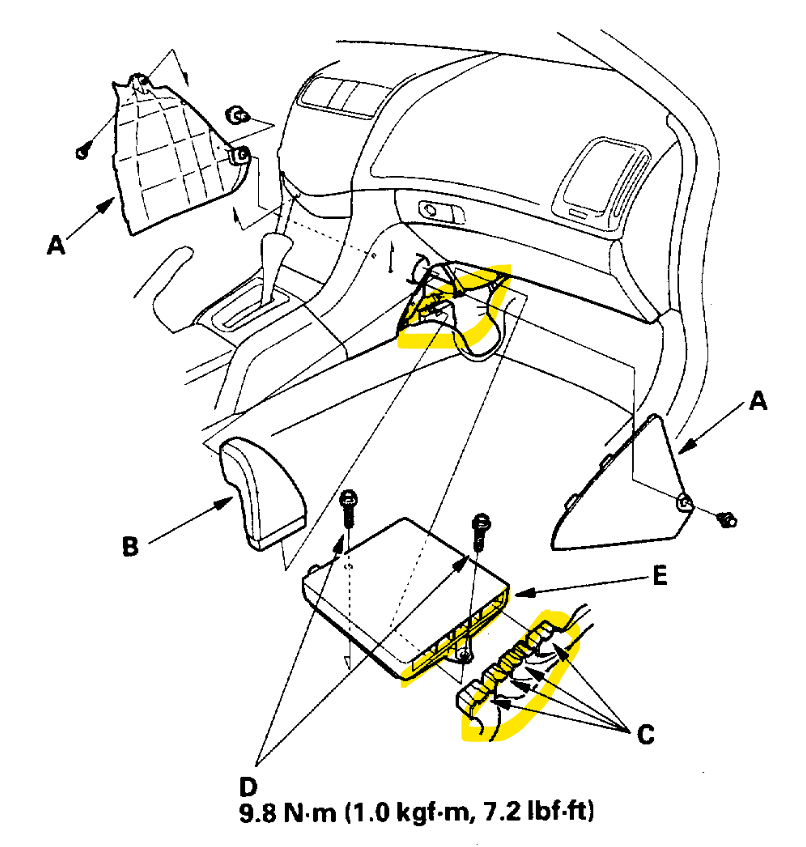
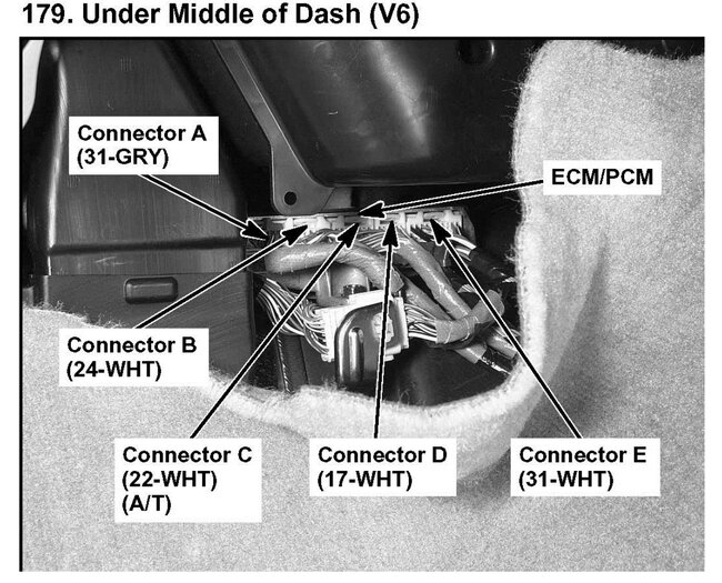
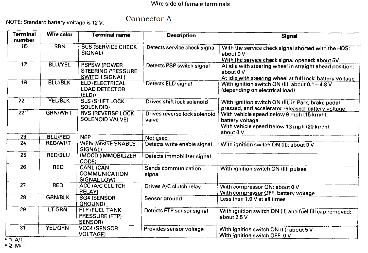
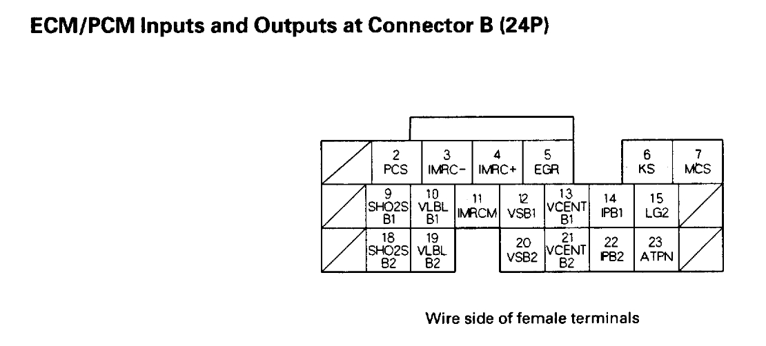
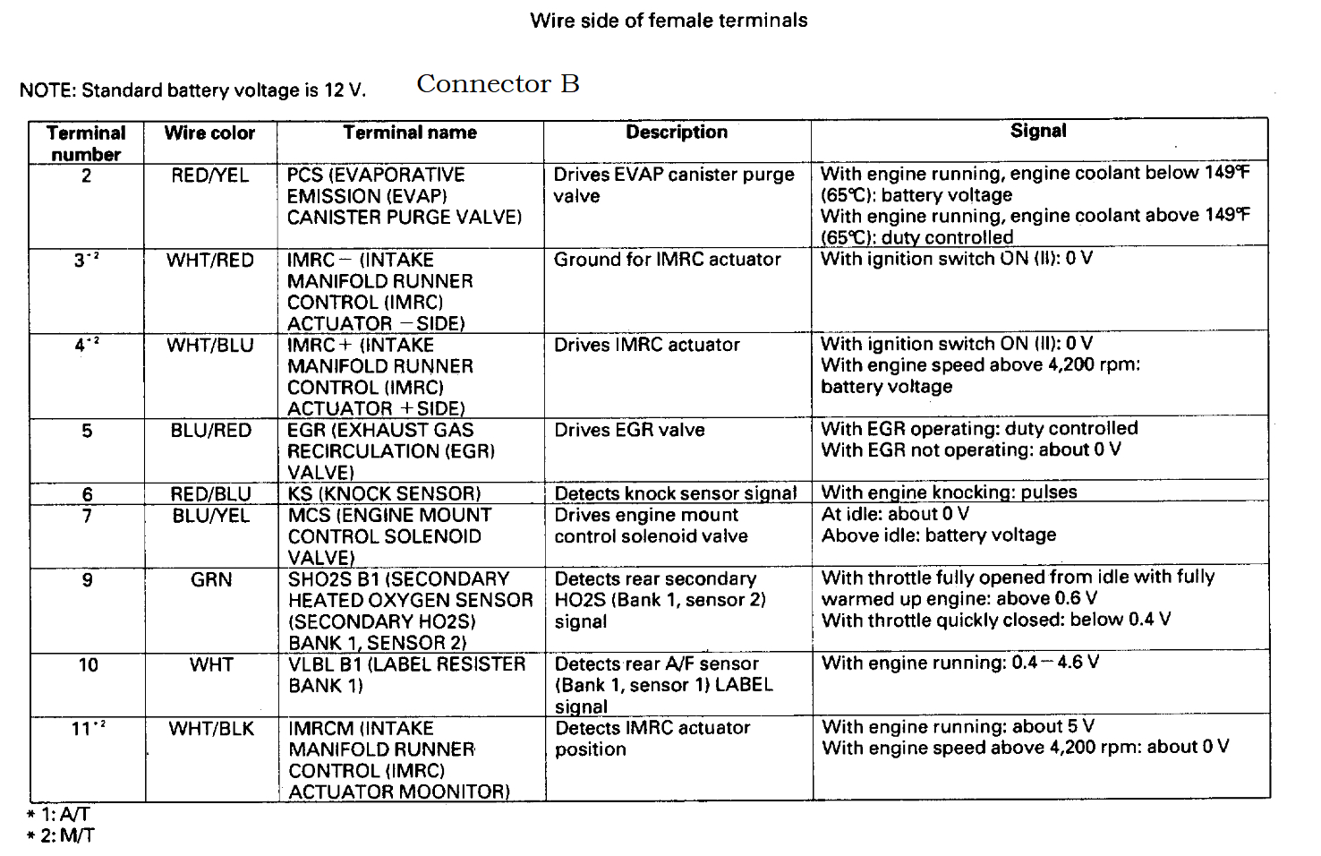
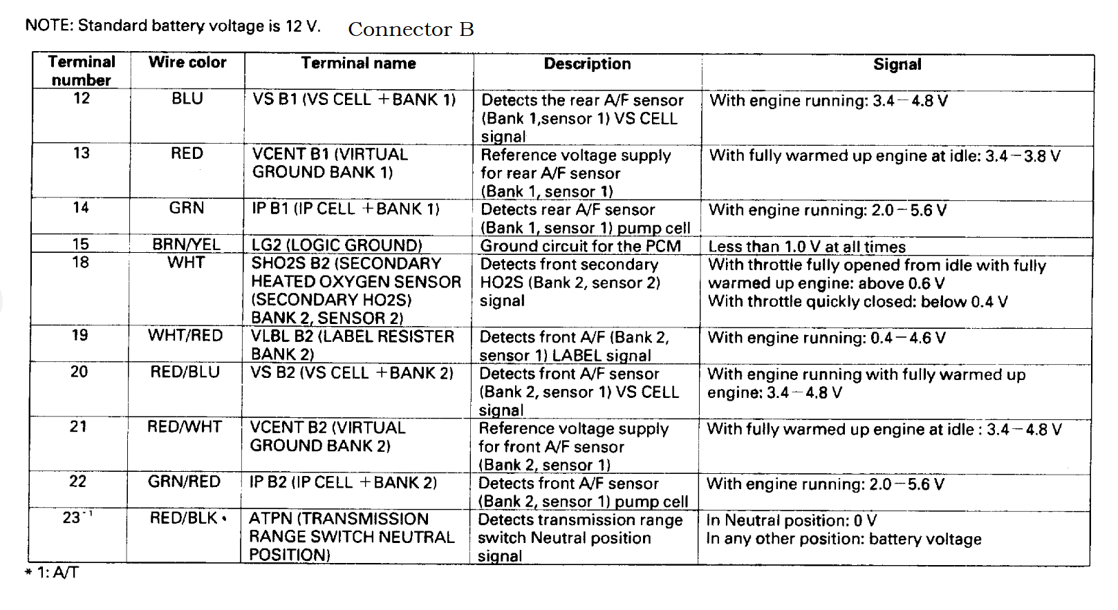
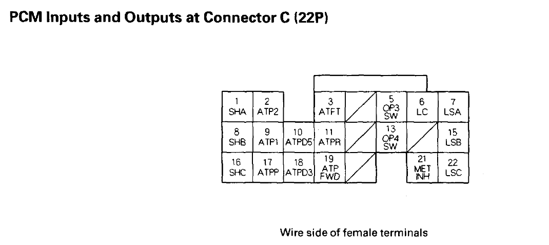
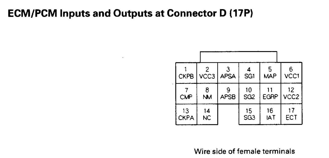
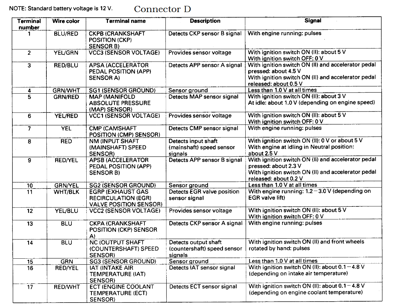
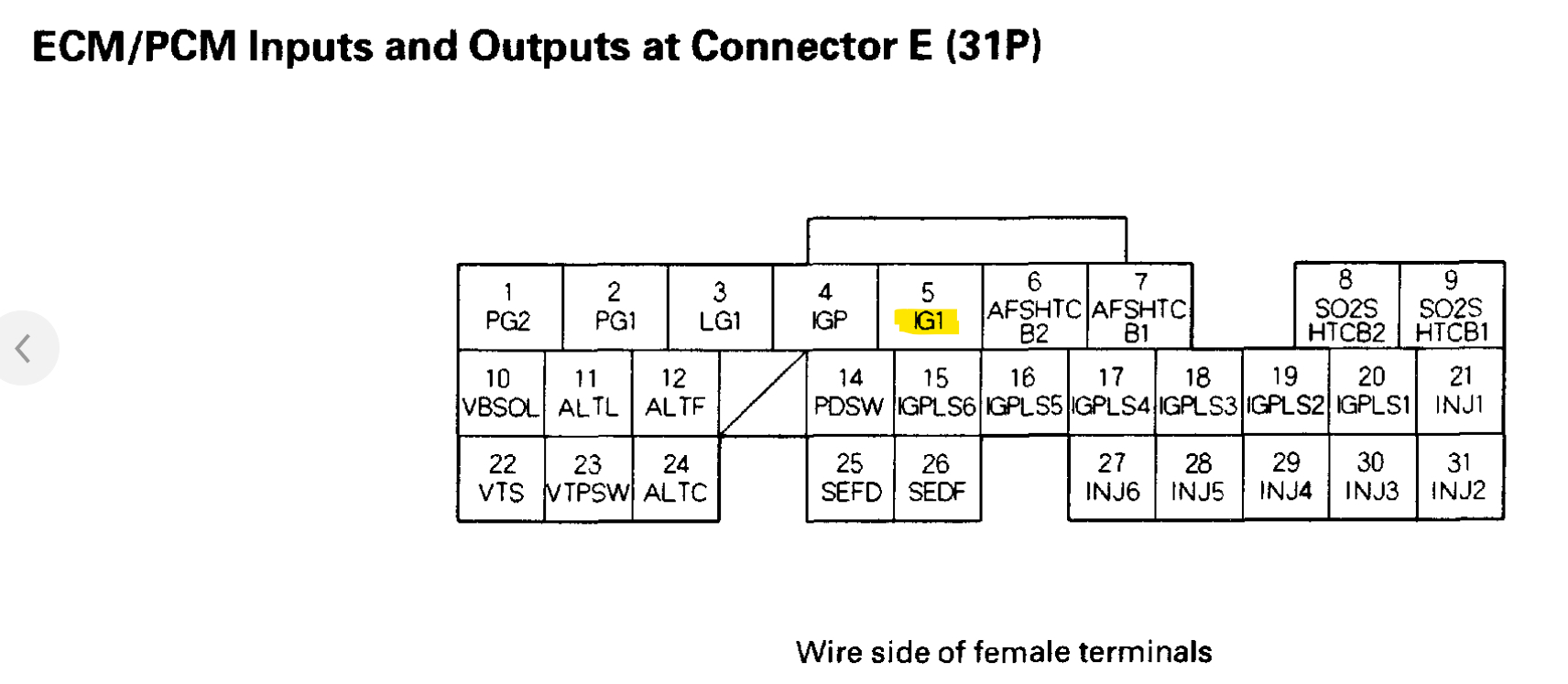
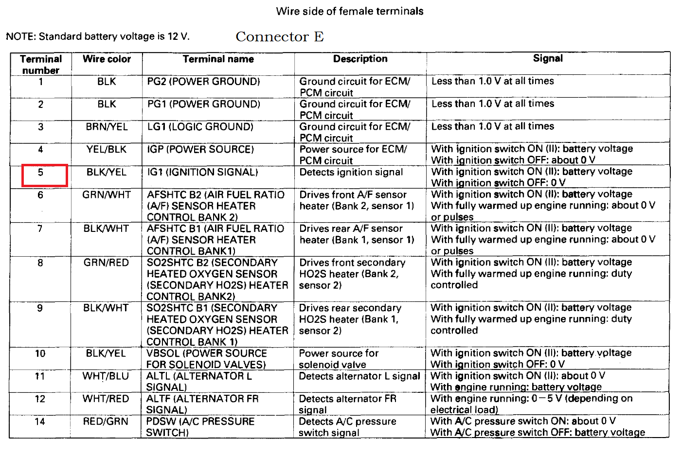
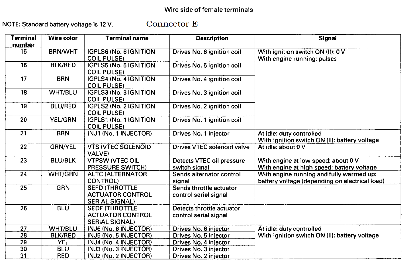
Diagrams 4 and 5 show the ECM location and connector letter A, B, C, D, E,
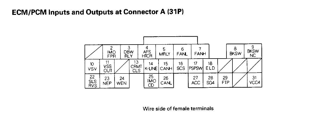
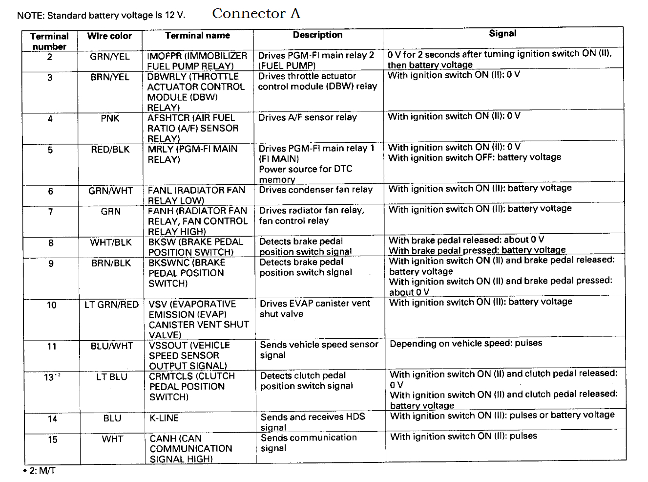
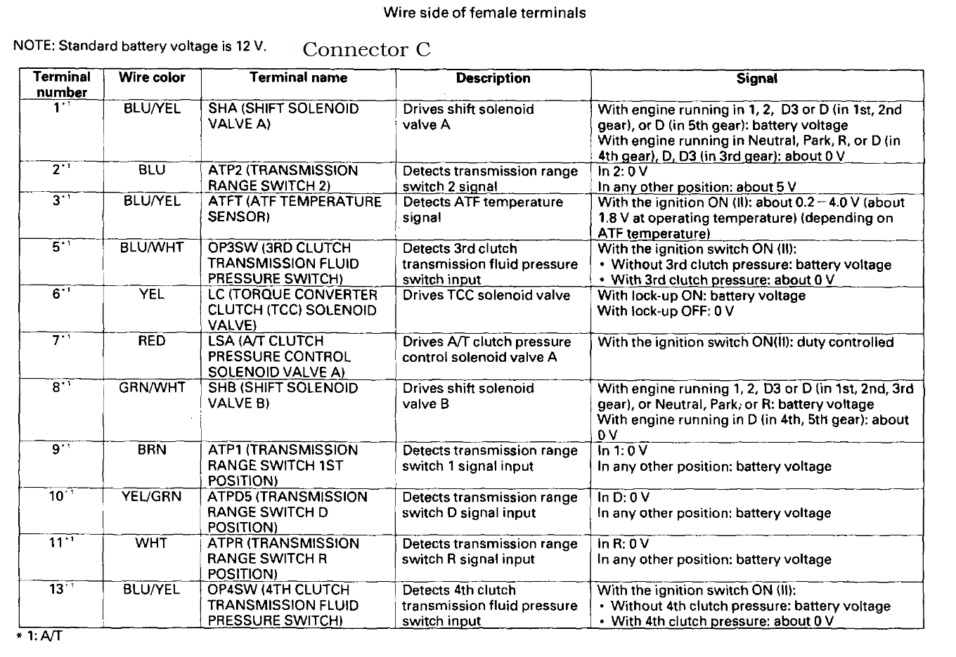
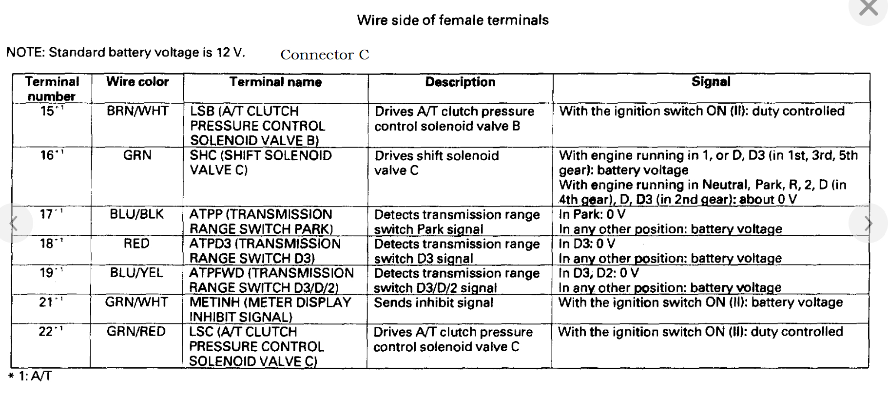
Each diagram after that shows each connector with its letter and then followed by 1 or 2 pages of the pinout value each wire should be, with the connector letter at the top, so you can check each one and know what should be there with the key On. This way you'll know exactly what is missing for power inputs.
Was this
answer
helpful?
Yes
No
Friday, May 26th, 2023 AT 11:42 AM

Please login or register to post a reply.

Sponsored links