Welcome to 2CarPros.
Before replacing any more parts, lets determine what is causing the no start after warm. First, it sounds like a bad crankshaft position sensor. The vehicle does have one located in the distributor. What happens is the coil winding in the sensor expand when they get hot and lose contact. Then, when it cools off, it will restart. Take a look through this link.
https://www.2carpros.com/articles/symptoms-of-a-bad-crankshaft-sensor
Now, when the engine stalls and won't restart, check to see if there is spark to the plugs. If there isn't, the sensor is my first suspect. Here is a link that shows how to test spark:
https://www.2carpros.com/articles/how-to-test-an-ignition-system
If you have spark, check for fuel pressure.
https://www.2carpros.com/articles/how-to-check-fuel-system-pressure-and-regulator
_________________
The quickest and easiest way to identify if the problem is related to the above links is to see if it will start with starting fluid. If it does, we know it's fuel related. If it doesn't it is ignition related.
If there is no spark, here are the directions specific to your vehicle regarding the crank sensor and how it works. It also shows location if you determine it needs replaced.
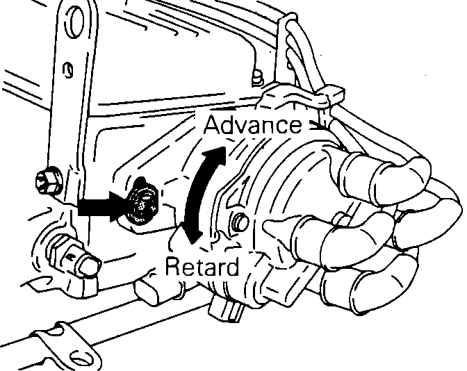
Distributor/Coil Assembly
Picture 1
The Crank Angle Sensor and the Top Dead Center Sensor are located within the unit housing. These sensors are incorporated into one unit, and consists of a disc and a pick-up unit. The disc is affixed to the main shaft and the light-transmitting unit is mounted stationary in the housing.
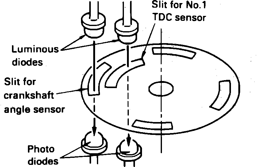
Crank Angle And #1 TDC Sensor
Picture 2
The disc contains 4 large slits around its circumference to indicate the crankshaft angle. An additional light-transmission slit located inward from the edge is used to indicate number one cylinder's top dead center position. The pick-up unit assembly uses two luminous diodes and two photo diodes, in order to detect the two different slits. There is a very slight clearance between the luminous diodes and the photo diodes, and the disc rotates within this space.
As the main shaft rotates the slits at the discs edge pass between the light and the optical reading part of the unit. The light emitted from the luminous diodes passes through the slits to the photo sensing diodes. When the photo diodes receive the light, they become conductive and generate a signal, which is sent to the Control Unit.
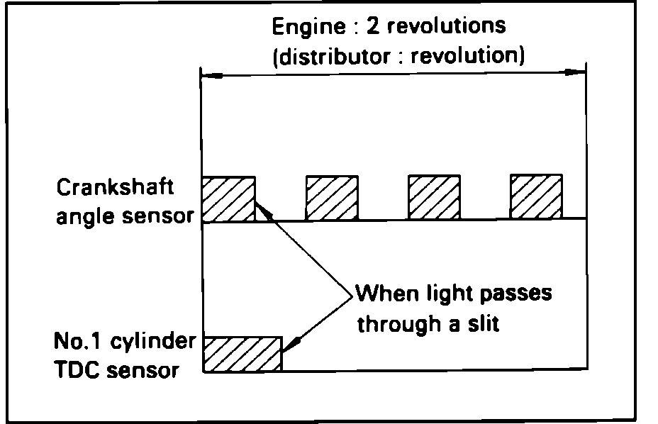
Photoelectric Signal Pattern
Picture 3
No.1 Cylinder TDC Signal:
Top dead center is detected by the signal obtained through the one inner slit of the disc. The MPI controller, based upon this signal, determines which of the four pulses from crank angle sensor is the signal for the #1 cylinder.
Crankshaft Angle Signal:
The four slits located at the outer circumference of the disc serve to detect the position of the crankshaft (and, therefore, the piston) relative to top dead center. The MPI controller, based on this signal, determines the fuel injection timing, and also calculates the amount of intake-air, the timing of the ignition signal, etc. for each revolution of the engine.
_____________________________________
Here are directions specific to your vehicle for testing fuel pressure. Specifications are included in the directions. Starting with picture 4, the remaining pics correlate with these directions.
OPERATIONAL CHECK (QUICK CHECK):
1. Turn the ignition switch OFF
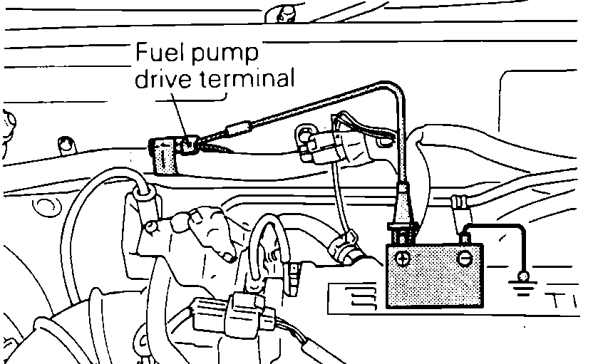
Fuel Pump Power Hook-up
Picture 4
2. Apply battery voltage to the fuel pump drive connector to power the fuel pump.
Fuel Pump Operational Test
Picture 5
3. Pinch the fuel hose to check that fuel pressure is felt.
NOTE: The fuel pump is mounted in the fuel tank and it operates submerged in fuel, therefore its operating sound is hard to hear without removing the fuel filler cap.
PRESSURE TEST (DIAGNOSTIC CHECK):
1. Reduce the internal pressure of the pipes and hoses by the following procedures.
a. Disconnect the fuel pump harness at the rear of the fuel tank.
b. Start and run the engine until it stalls. Turn OFF the ignition key.
c. Disconnect the battery negative terminal.
d. Connect the fuel pump harness connector.
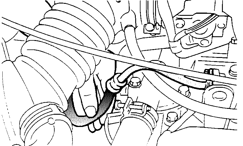
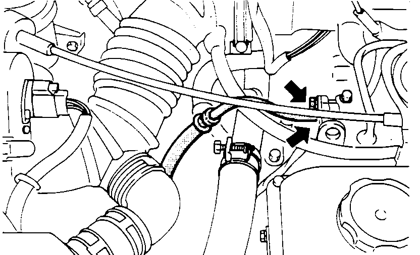
High Pressure Fuel Hose Connection
Picture 6
2. Disconnect the high pressure fuel hose at the delivery end.
CAUTION: Cover the hose connector with a shop towel to prevent splashing of fuel caused by residual pressure in the fuel line.
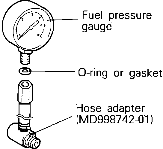
Fuel Pressure Testing Equipment And Adapter
Picture 7
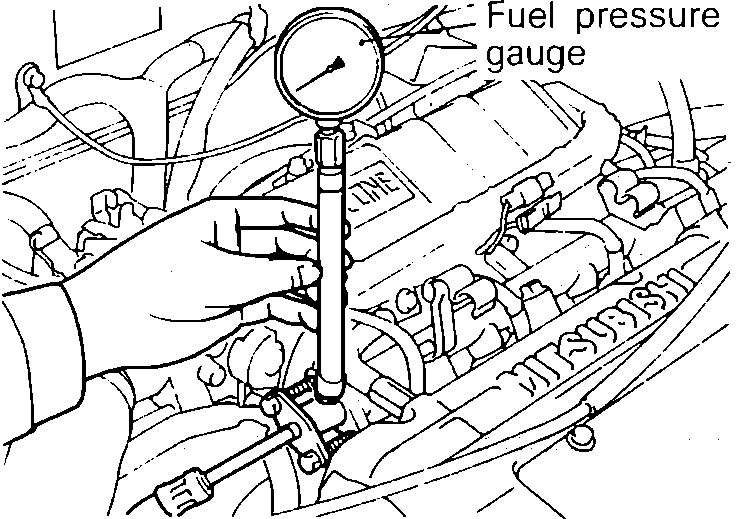
Fuel Pump Pressure Test Equipment Installed
Picture 8
3. Using the fuel pressure gauge adapter (MD998742-01) or equivalent, install the fuel-pressure gauge to the delivery pipe (fuel rail).
4. Connect the battery negative terminal.
5. Apply battery power to the fuel pump drive terminal to activate the fuel pump. With fuel pressure applied check that no fuel is leaking at any of the connections.
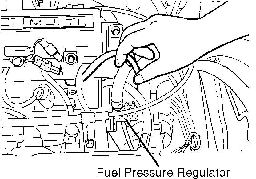
Fuel Pressure Regulator W/Vacuum Line Disconnected
Picture 9
6. Disconnect the vacuum hose from the pressure regulator, and plug the hose end. Measure the fuel pressure at idle.
Standard Value: 47-50 psi (330-350 kPa)
7. Measure the fuel pressure when the vacuum hose is connected to the pressure regulator.
Standard Value: 38 psi (270 kPa).
NOTE: At the completion of steps 5 thru 7, prior to turning the ignition off, disconnect the battery power to the fuel pump drive terminal. If the engine stops and no fuel pressure is observed, there is a problem in the power supply to the fuel pump.
8. If the results of the measurements made in steps 6 and 7 are not within the standard values, refer to the symptoms listed below to determine the probable cause and make the necessary repairs before re-testing.
a. Fuel pressure too low:
1. Clogged fuel filter---Replace
2. Fuel bleeds down to return hose---Replace the fuel pressure regulator
3. Low pump output pressure---Check for leak in-line or replace fuel pump
b. Fuel pressure too high:
1. Regulator stuck closed---Replace the fuel pressure regulator
2. Clogged or bent fuel return hose---repair hose
c. No difference with or without vacuum connected:
1. Non-responsive regulator---Replace the fuel pressure regulator
2. Plugged vacuum line or no source vacuum---replace line or repair vacuum source
9. Stop the engine and check for a change in fuel pressure readings. Pressure should hold for 5 minutes. If the gauge reading drops, observe the rate of drop. Determine the cause according to the following symptoms.
a. Fuel pressure drops slowly:
1. Injector leakage---Identify leaking injector and replace.
2. Regulator is leaking to return line---Confirm and replace regulator.
3. Check valve in the fuel pump is leaking---Replace the pump.
b. Fuel pressure drops immediately:
1. Regulator is leaking to return line---Confirm and replace regulator.
2. Check valve in the fuel pump is open---Replace the pump.
_______________________________________
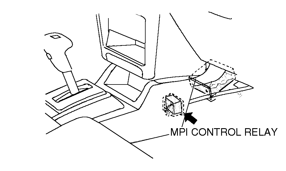
Let me know if this helps or if you have other questions. If you want to try the relay, it is located behind the center console, passenger side. See the last picture I listed.
Take care,
Joe
Images (Click to enlarge)
Feb 27, 2019 at 8:51 PM