Hi and thanks for using 2CarPros.
Since you had the battery disconnected for an extended period, the computer may be going through a relearn. Have you driven the vehicle to put any miles on it?
As far as the one wheel spinning and not the other, that is somewhat normal. Under normal conditions, the wheel with the least resistance turns.
As far as the fuel leak, any is dangerous. Check for loose connections or damaged hoses. You may have damaged one when working with the clutch.
Here are the directions for the work you did from Alldata. Read through it to see if you missed anything. Also, the attached pictures correlate with these directions.
__________________________________
PRESSURE PLATE, CLUTCH DISC, FLYWHEEL, RELEASE BRG SERVICE
Clutch Replacement
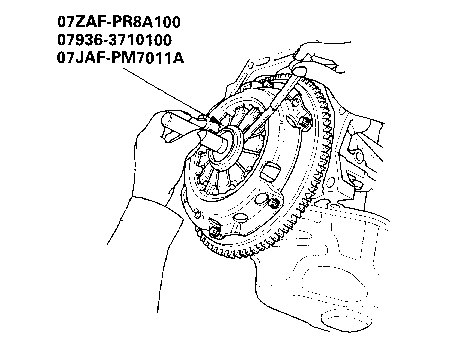
Special Tools Required
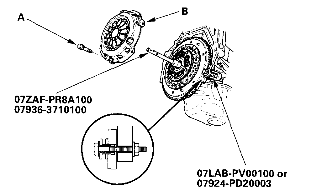
Clutch alignment disc 07JAF-PM7011A
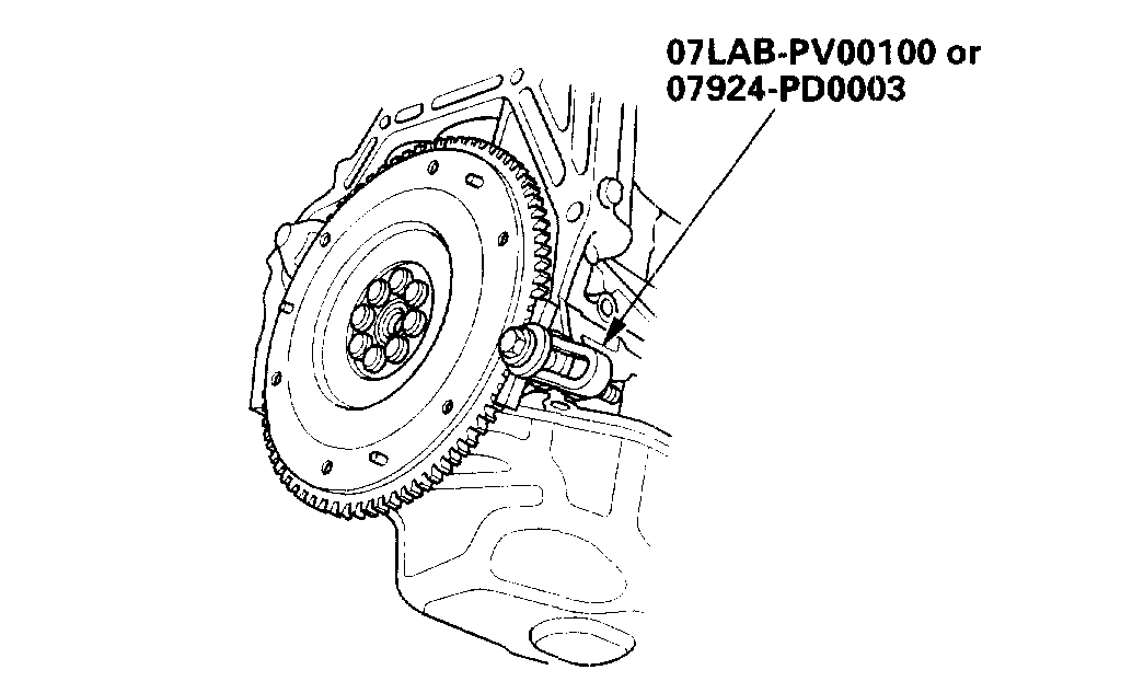
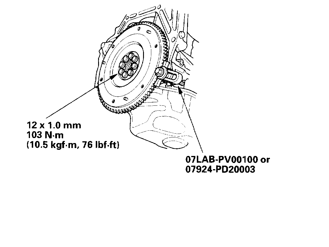
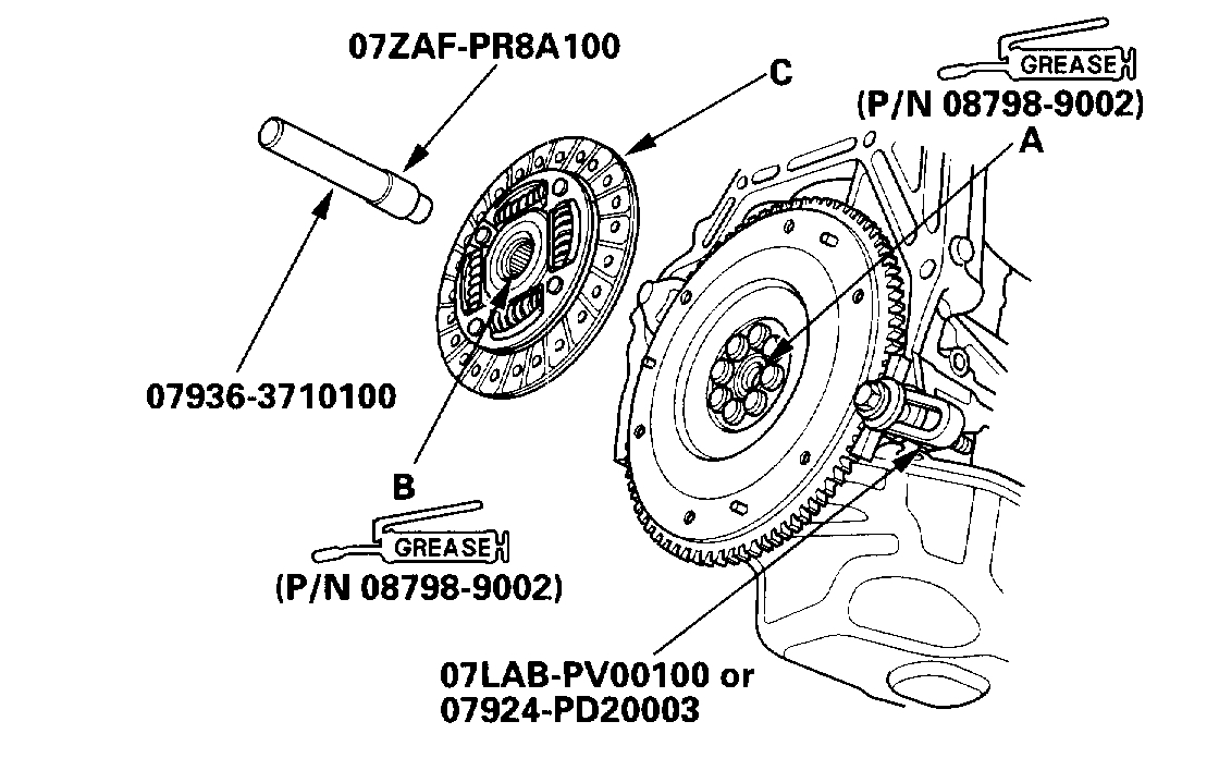
Ring gear holder 07LAB-PV00100 or 07924-PD20003
Clutch alignment shah 07ZAF-PR8A100
Remover handle 07936-3710100
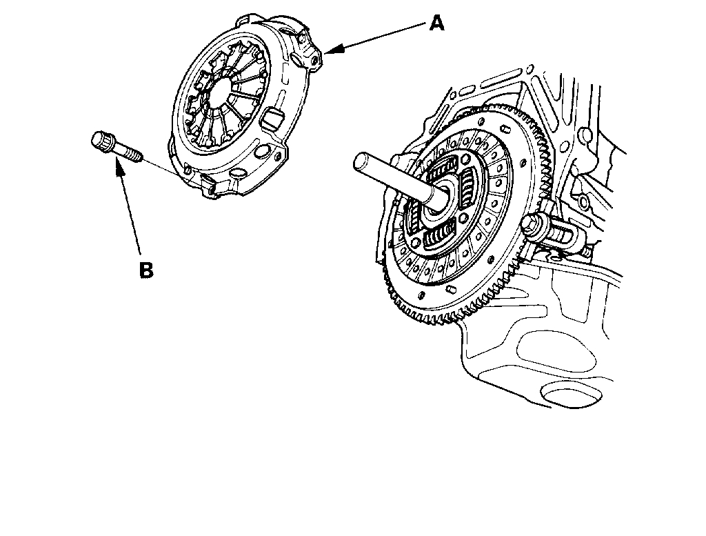
Pressure Plate and Clutch Disc Removal
1. Check the diaphragm spring fingers height using the special tool and feeler gauge. If the height is more than the service limit, replace the pressure plate.
Standard (New): 0.6 mm (0.02 inch) max.
Service Limit: 0.8 mm (0.03 inch)
2. Install the special tools.
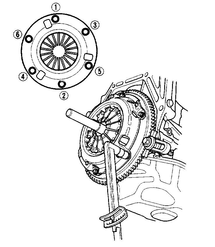
3. To prevent warping, unscrew the pressure plate mounting bolts (A) in a crisscross pattern in several steps, then remove the pressure plate (B).
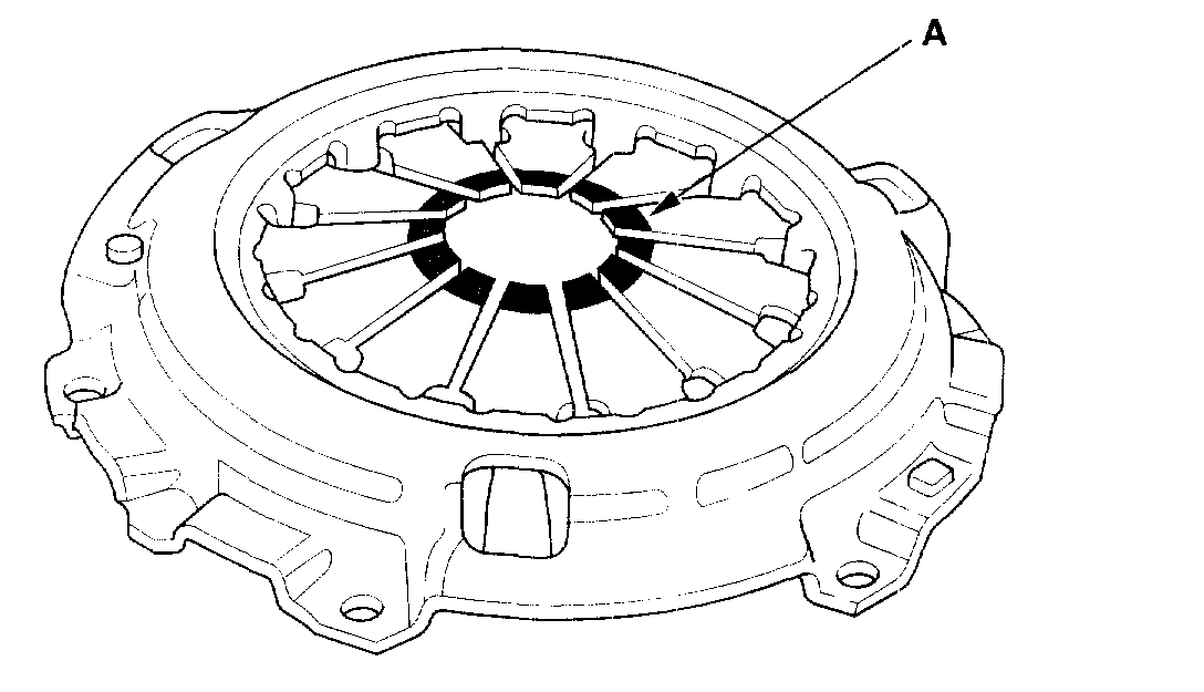
4. Inspect the fingers of the diaphragm spring (A) for wear at the release bearing contact area.
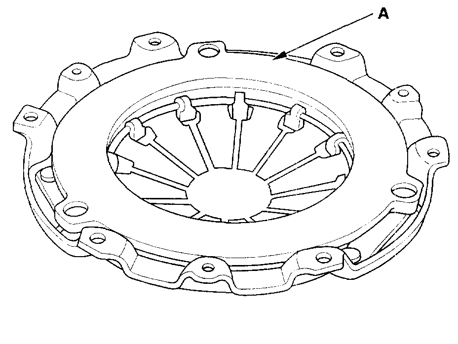
5. Inspect the pressure plate (A) surface for wear, cracks, and burning.
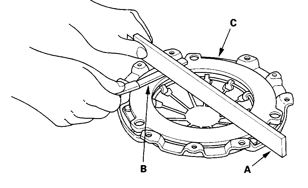
6. Inspect for warpage using a straight edge (A) and feeler gauge (B). Measure across the pressure plate (C). If the warpage is more than the service limit, replace the pressure plate.
Standard (New): 0.03 mm (0.001 inch) max.
Service Limit: 0.15 mm (0.006 inch)
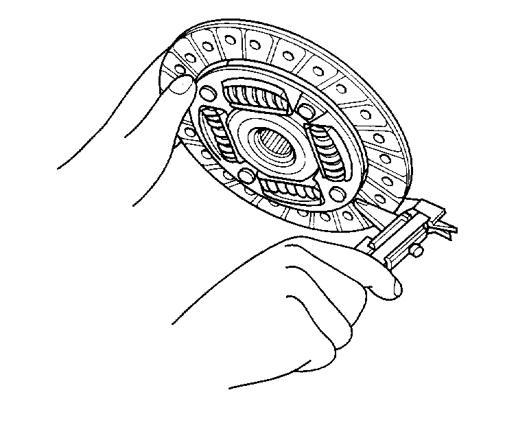
7. Remove the clutch disc and special tools.
8. Inspect the lining of the clutch disc for signs of slipping or oil. If the clutch disc is burned black or oil soaked, replace it.
9. Measure the clutch disc thickness. If the thickness is less than the service limit, replace the clutch disc.
Standard (New): 8.6 - 9.2 mm (0.343 - 0.366 inch)
Service Limit: 6.0 mm (0.24 inch)
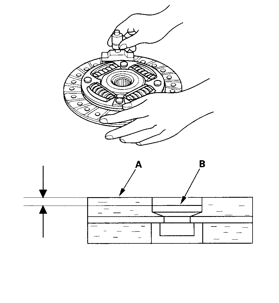
10. Measure the rivet depth from the clutch disc lining surface (A) to the rivets (B) on both sides. If the rivet depth is less than the service limit, replace the clutch disc.
Standard (New): 1.65 - 2.25 mm (0.065 - 0.089 inch)
Service Limit: 0.7 mm (0.03 inch)
Flywheel Inspection
1. Inspect the ring gear teeth for wear and damage.
2. Inspect the clutch disc mating surface on the flywheel for wear, cracks, and burning.
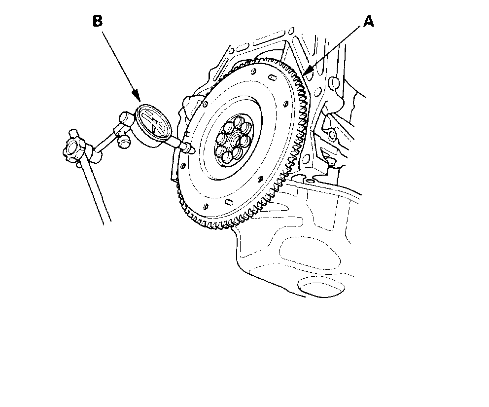
3. Measure the flywheel (A) runout using a dial indicator (B) through at least two full turns with the engine installed. Push against the flywheel each time you turn it to take up the crankshaft thrust washer clearance. If the runout is more than the service limit, replace the flywheel and recheck the runout. Resurfacing the flywheel is not recommended.
Standard (New): 0.05 mm (0.002 inch) max.
Service Limit: 0.15 mm (0.006 inch)
Flywheel Replacement
1. Install the special tool.
2. Remove the flywheel mounting bolts in a crisscross pattern in several steps, then remove the flywheel.
3. Install the flywheel on the crankshaft, and install the mounting bolts finger-tight.
4. Install the special tool, then torque the flywheel mounting bolts in a crisscross pattern in several steps.
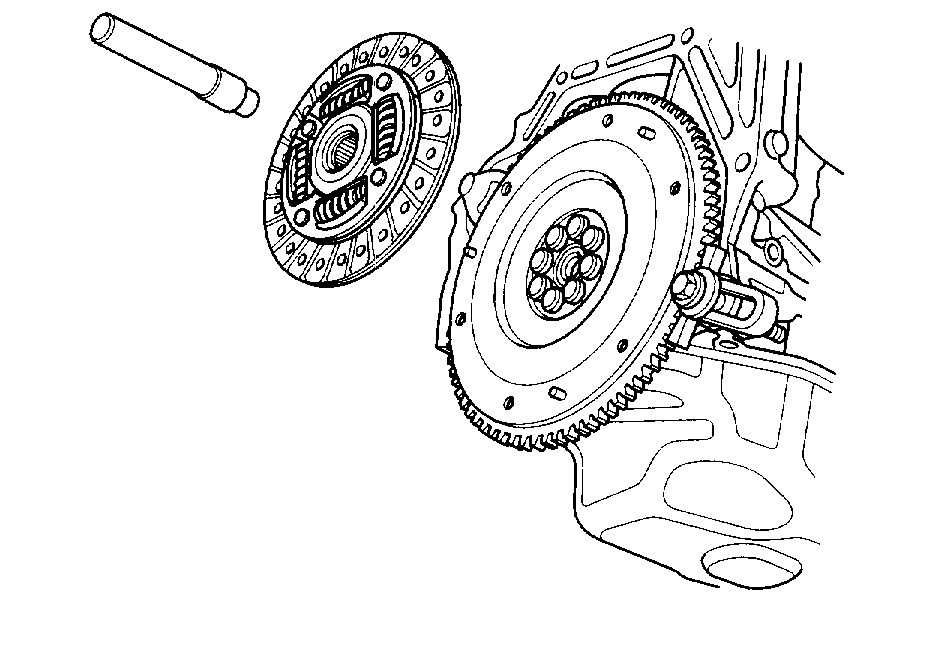
Clutch Disc and Pressure Plate Installation
1. Temporarily install the clutch disc onto the splines of the transmission mainshaft. Make sure the clutch disc slides freely on the mainshaft.
2. Install the ring gear holder.
3. Apply a light coat of super high temp urea grease (P/N 08798-9002) to the crankshaft pilot bushing (A).
4. Apply super high temp urea grease (P/N 08798-9002) to the splines (B) of the clutch disc (C), then install the clutch disc using the special tools.
5. Install the pressure plate (A) and the mounting bolts (B) finger-tight.
6. Torque the mounting bolts in a crisscross pattern. Tighten the bolts in several steps to prevent warping the diaphragm spring.
PRESSURE PLATE MOUNTING BOLT TORQUE: 25 Nm (2.6 kgf-m, 19 ft. Lbs.)
7. Remove the special tools.
8. Make sure the diaphragm spring fingers are all the same height.
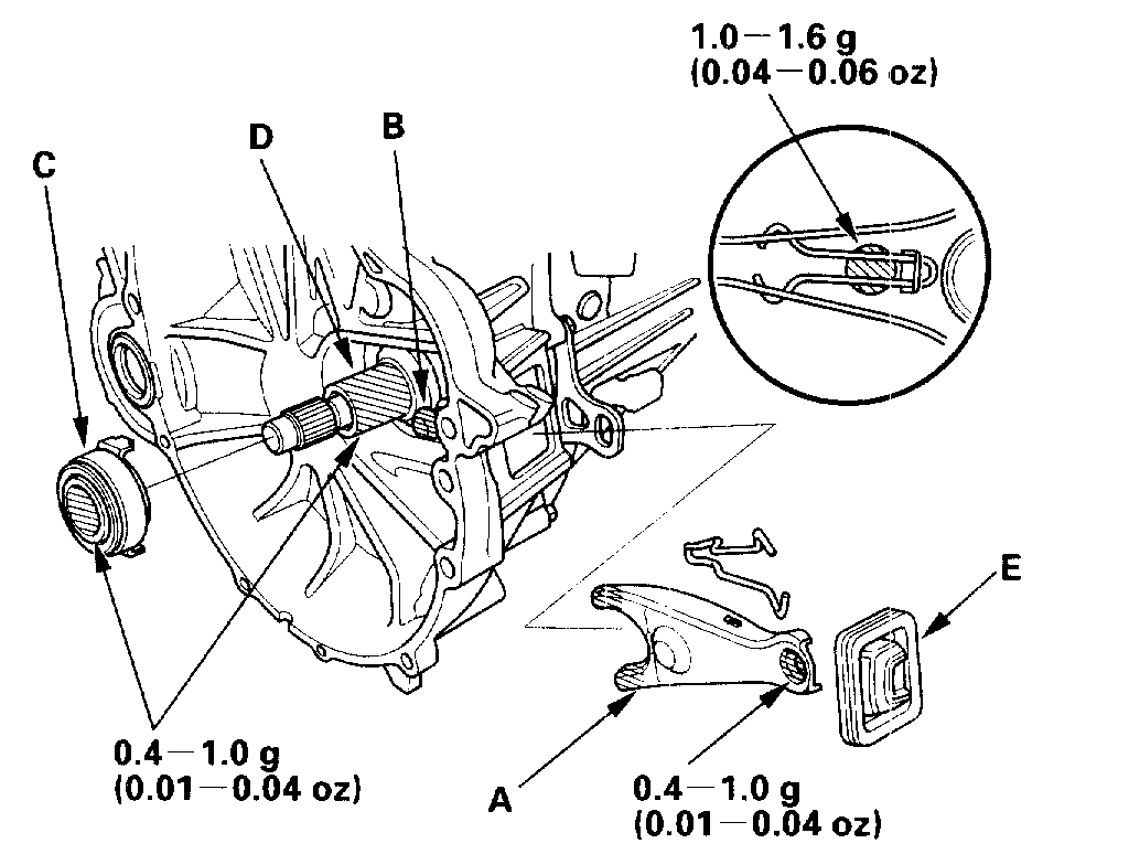
Release Bearing Replacement
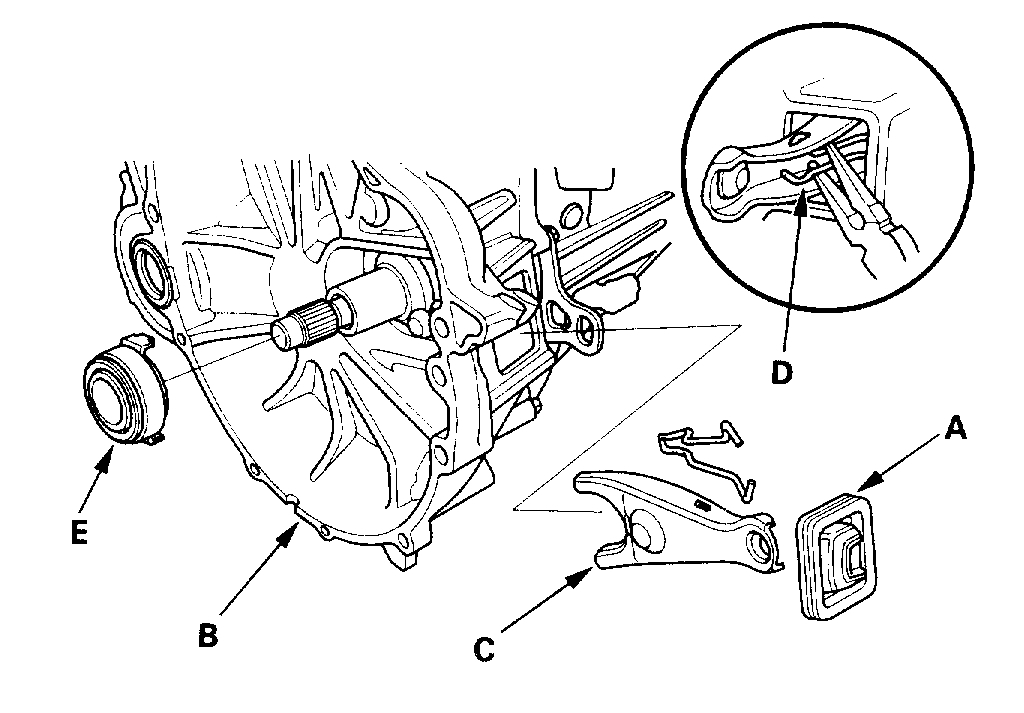
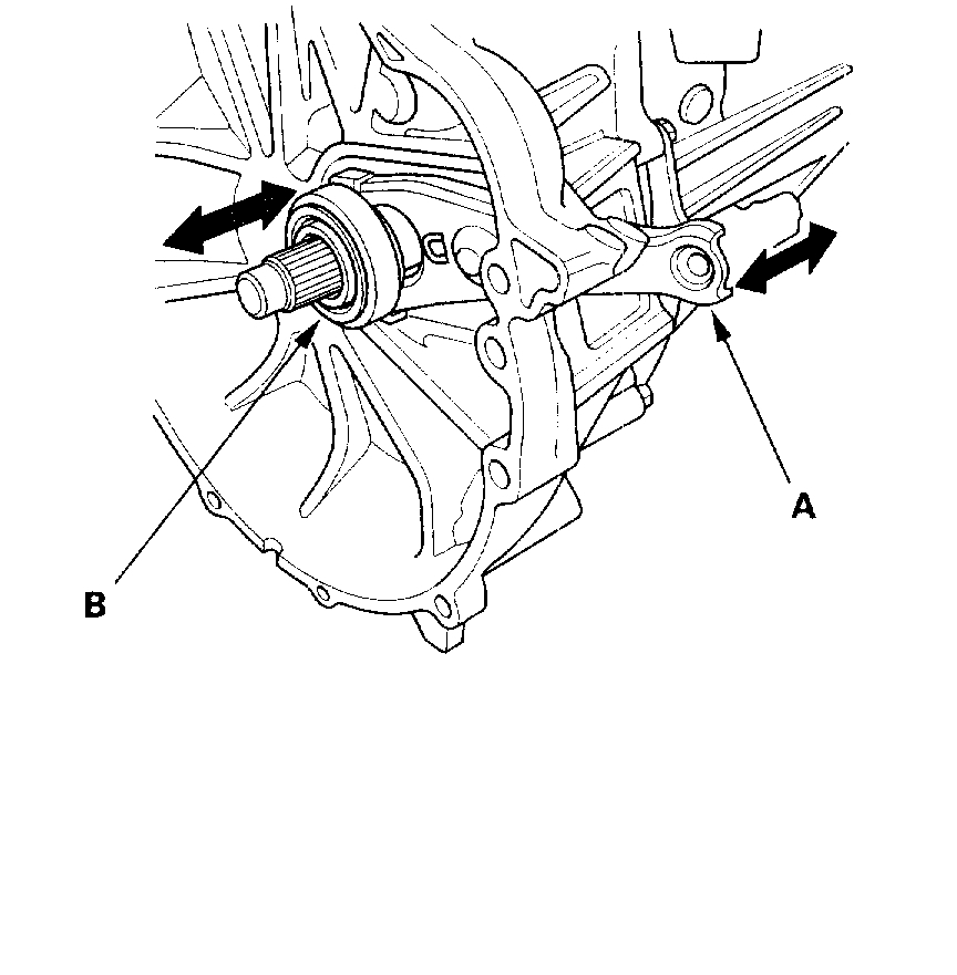
1. Remove the release fork boot (A) from the clutch housing (B).
2. Remove the release fork (C) from the clutch housing (B) by squeezing the release fork set spring (D) with pliers. Remove the release bearing (E).
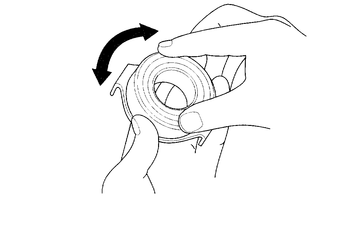
3. Check the release bearing for play by spinning it by hand. If there is excessive play, replace the release bearing with a new one.
NOTE: The release bearing is packed with grease. Do not wash it in solvent.
4. Apply super high temp urea grease (P/N 08798-9002) to the release fork (A), the release fork bolt (B), the release bearing (C), and the release bearing guide (D) in the shaded areas.
5. With the release fork slid between the release bearing pawls, install the release bearing on the mainshaft while inserting the release fork through the hole in the clutch housing.
6. Align the detent of the release fork with the release fork bolt, then press the release fork over the release fork bolt squarely.
7. Install the release fork boot (E). Make sure the boot seals around the release fork and clutch housing.
8. Move the release fork (A) right and left to nuke sure that it fits properly against the release bearing (B) and that the release bearing slides smoothly.
_________________________________________________________
I hope this helps. Let me know if you have other questions and if possible, the answers to my questions.
Take care,
Joe
Images (Click to make bigger)
Thursday, December 20th, 2018 AT 8:54 PM