Here are the procedures for checking the idling system.
IDLE CONTROL SYSTEM
NOTE: For idle control system testing not listed, perform related DTC testing procedure. See appropriate SELF - DIAGNOSTICS article.
Idle Air Control (IAC) System Diagnosis
1 . If On-Board Diagnostic (OBD) system check has been performed, go to next step. If On- Board Diagnostic (OBD) system check has not been performed, perform On-Board Diagnostic (OBD) system check.
2 . Set parking brake and block wheels. Turn A/C off. Start engine and let idle. Install scan tool and select SPECIAL FUNCTIONS. Select IAC SYSTEM TEST, and then RPM CONTROL. Using scan tool, command engine speed to 500 RPM. If actual engine RPM is
within 100 RPM of scan tool display, go to next step. If actual engine RPM is not within 100 RPM of scan tool display, go to step 4 .
3 . Using scan tool, command engine speed to 1200 RPM. If actual engine RPM is within 100 RPM of scan tool display, check for a non-IAC system problem (i.e., vacuum leak, sticking throttle cable, fuel system lean or rich, throttle body, poor electrical connections, faulty PCV valve, A/C compressor circuits). If actual engine RPM is not within 100 RPM of scan tool display, go to step 5 .
4 . Check for vacuum leaks, sticking throttle plates, faulty PCV valve, or restriction in air induction system. If problem exists, go to step 20 . If problem does not exist, go to step 6 .
5 . Check for obstruction or excessive carbon deposit in throttle body IAC passages. If problem exists, go to step 21 . If problem does not exist, go to next step.
6 . Turn ignition off. Disconnect IAC valve harness connector. Check for poor connection at IAC valve. If problem exists, go to step 19 . If problem does not exist, go to next step.
7 . Connect IAC Driver (J-37027 -A) to IAC valve. Set parking brake and block wheels. Turn A/C off. Start engine and let idle. Install scan tool and monitor engine RPM. Using IAC driver, extend and retract IAC valve. If engine RPM decreases and increases as IAC valve is cycled, go to next step. If engine RPM does not decrease and increase as IAC valve is
cycled, go to step 22 .
8 . If RPM changes smoothly with each flash of IAC valve cycle, go to next step. If RPM does not change smoothly with each flash of IAC valve cycle, go to step 22 .
9 . Install appropriate IAC node light onto IAC valve harness connector. Cycle IAC driver and observe lights. Both lights should cycle Green to Red, but never off as RPM changed over its range. If lights flash as specified, go to next step. If lights do not flash as specified, go to step 12 .
10 . Remove IAC driver from IAC valve. Using DVOM, measure resistance between IAC valve terminals "A" and "B". See Fig. 7 . Also, measure resistance between IAC valve terminals "C" and "D". If resistance is 40 - 80 ohms on both measurements, go to next step. If resistance is not 40 - 80 ohms on both measurements, go to step 22 .
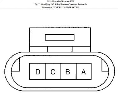
11 . Using DVOM, measure resistance between IAC valve terminals "B" and "C". See Fig. 7 . Also, measure resistance between IAC valve terminals "A" and "D". If resistance is infinite on both measurements, check for a non-IAC system problem (i.e. vacuum leak, sticking throttle cable, fuel system lean or rich, throttle body, poor electrical connections, faulty PCV valve, A/C compressor circuits). If resistance is not infinite on both measurements, go to step 22 .
12 . Turn ignition off. Disconnect PCM/VCM harness connectors. Check for poor connections at PCM/VCM. If problem exists, go to step 19 . If problem does not exist, go to next step.
13 . Remove IAC node light. Check for an open in IAC driver circuits between IAC valve harness connector and PCM/VCM harness connector. If problem exists, go to step 19 . If problem does not exist, go to next step.
14 . Using a test light connected to battery voltage, probe IAC valve harness connector terminals. If test light illuminates at any terminal, go to step 17 . If test light does not illuminate at any terminal, go to next step.
15 . Turn ignition on with engine off. Using a test light connected to ground, probe IAC valve harness connector terminals. If test light illuminates at any terminal, go to step 18 . If test light does not illuminate at any terminal, go to next step.
16 . Check for a short between IAC valve circuits. If problem exists, go to step 19 . If problem does not exist, go to step 23 .
17 . Repair short to ground in IAC circuit. After repairs, go to step 24 .
18 . Repair short to voltage in IAC circuit. After repairs, go to step 24 .
19 . Repair circuit as necessary. After repairs, go to step 24 .
20 . Repair condition as necessary. After repairs, go to step 24 .
21 . Clean IAC passages. After repairs, go to step 24 .
22 . Replace IAC valve. After repairs, go to step 24 .
23 . Replace PCM/VCM. Program PCM/VCM. Perform VTD password relearn procedure and crankshaft variation learn procedure.After repairs, go to next step.
24 . Install scan tool. Start engine and let idle. Turn off all accessories. Using scan tool, command engine speed to 1200 RPM, and then down to 500 RPM. Again, using scan tool, command engine speed as specified. If actual RPM is close to commanded RPM, system is okay. If actual RPM is not close to commanded RPM, go to step 2 .
Oct 23, 2009 at 3:15 PM
