Hi,
Most commonly, what you described is caused by warped brake rotors and not a wheel bearing. Rather than having them resurfaced, just replace them. Once they are resurfaced, they are thinner and will warp faster. I would also recommend replacing the brake pads at the same time.
Here is a link showing how, in general, pads and rotors are replaced:
https://www.2carpros.com/articles/how-to-replace-front-brake-pads-and-rotors-fwd
Here are the directions specific to your vehicle. The attached pics correlate with the directions. Note: The directions are for rotor replacement. You will already have the pads off to replace the rotor.
_______________________________________
2004 Chevrolet Malibu L4-2.2L VIN F
Front
Vehicle Brakes and Traction Control Disc Brake System Brake Rotor/Disc Service and Repair Procedures Brake Rotor Replacement Front
FRONT
Brake Rotor Replacement- Front
^ Tools Required
- J 41013 Rotor Resurfacing Kit
- J 42450-A Wheel Hub Resurfacing Kit
Removal Procedure
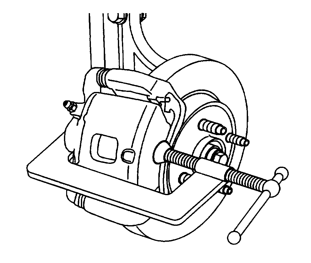
pic 1
Caution: Refer to Brake Dust Caution in Service Precautions.
1. Raise and support the vehicle.
2. Remove the tire and wheel assembly.
3. Install a C-clamp over the body of the brake caliper, with the C-clamp ends against the rear of the caliper body and the outboard disc brake pad.
4. Tighten the C-clamp until the caliper piston is compressed into the caliper bore enough to allow the caliper to slide past the brake rotor.
5. Remove the C-clamp.
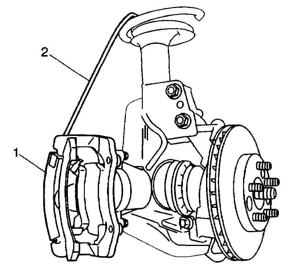
pic 2
Notice: Support the brake caliper with heavy mechanic's wire, or equivalent. whenever it is separated from its mount and the hydraulic flex Ale brake hose is still connected. Failure to support the caliper in this manner will cause the flexible brake hose to bear the weight of the caliper, which may cause damage to the brake hose and in turn may cause a brake fluid leak.
Important: Do NOT disconnect the hydraulic bake flexible hose from the caliper.
6. Remove the brake caliper and the caliper mounting bracket as an assembly from the steering knuckle and support the assembly with heavy mechanic's wire (2), or equivalent. Ensure that there is no tension on the hydraulic brake flexible hose.
7. Matchmark the position of the brake rotor to the wheel studs.
8. Remove the brake rotor.
Installation Procedure
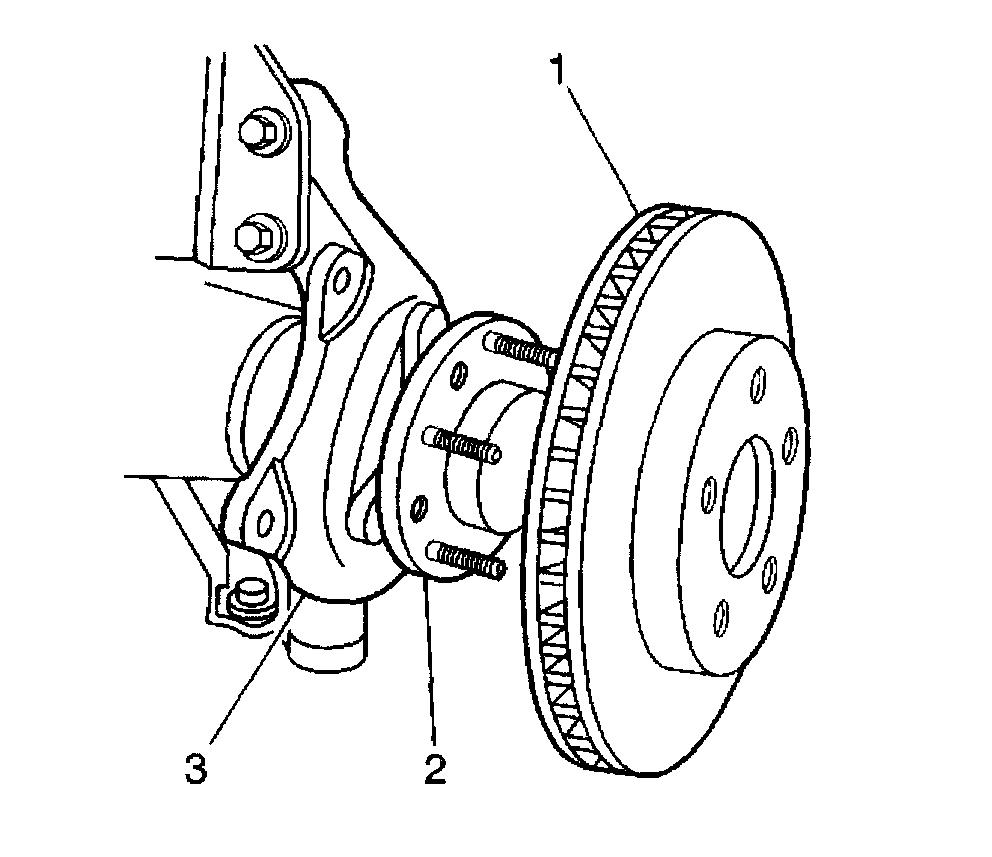
pic 3
Important: Whenever the brake rotor has been separated from the hub/axle flange, any rust or contaminants should be cleaned from the hub axle flange and the brake rotor mating surfaces. Failure to do this may result in excessive assembled lateral runout (LRO) of the brake rotor. which could fetid to brake pulsation.
1. Using the J 42450-A thoroughly clean any rust or corrosion from the mating surface of the hub/axle flange.
2. Using the J 41013, thoroughly clean any rust or corrosion from the mating surface and mounting surface of the brake rotor.
3. Inspect the mating surfaces of the hub/axle flange and the rotor to ensure that there are no foreign particles or debris remaining.
4. Install the brake rotor to the hub/axle flange.. Use the matchmark made prior to removal for proper orientation to the flange.
5. If the brake rotor was removed and installed as part of a brake system repair, measure the assembled lateral runout (LRO) of the brake rotor to ensure optimum performance of the disc brakes.
6. If the brake rotor assembled LRO measurement exceeds the specification, bring the LRO to within specifications.
7. Remove the support, and install the brake caliper and the brake caliper bracket as an assembly to the steering knuckle.
8. Install the tire and wheel assembly.
9. Lower the vehicle.
10. If the brake rotor was refinished or replaced, or if new brake pads were installed, burnish the pads and rotors.
________________________________________________
I hope this helps. Let me know if you have other questions.
Take care and God Bless,
Joe
Images (Click to enlarge)
Feb 4, 2021 at 6:23 PM