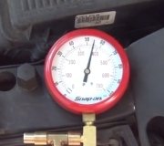
It will if the car is running, but not just key on...No pressure comming out of the tank? If it's a pump you need to attach the leads to, se if you have those reversed, it may be pumping back into the tank...Or outlet tube isnt hook up right?
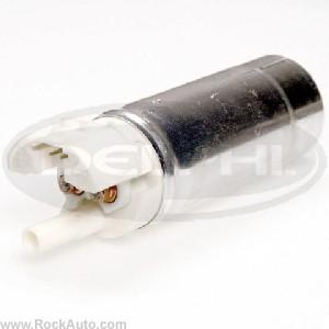
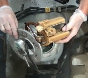
FUEL SYSTEM FUEL DELIVERY Fuel Pump An in-tank electric fuel pump delivers fuel to injectors through an in-line fuel filter. The pump is designed to supply fuel pressure in excess of vehicle requirements. The pressure relief valve in the fuel pump controls maximum fuel pump pressure. A pressure regulator, mounted in fuel rail (port injection systems) or on throttle body unit (throttle body injection systems), keeps fuel available to injectors at a constant pressure. Excess fuel is returned to fuel tank through pressure regulator return line. For fuel pressure specifications, see SPECIFICATIONS article in this section. When the ignition switch is turned to ON position, ECM will turn on the electric fuel pump by energizing the fuel pump relay. The ECM will continue to energize relay if the engine is running or cranking (ECM is receiving reference pulses from the ignition module). If no reference pulses exist, ECM de-energizes fuel pump relay within 2 seconds after ignition is turned on. For additional information, see FUEL PUMP RELAY below. Fuel Pump Relay When the ignition switch is turned to the ON position, ECM will turn on the electric fuel pump by energizing the fuel pump relay. The ECM will keep the relay energized if the engine is running or cranking (ECM is receiving reference pulses from the ignition module). If no reference pulses exist, ECM turns pump off within 2 seconds after key on. As a back-up system to fuel pump relay, fuel pump is also activated by the oil pressure switch. The oil pressure switch is normally open until oil pressure reaches approximately 4 psi (.28 kg/cm 2 ). If fuel pump relay fails, the oil pressure switch closes when oil pressure is obtained, operating the fuel pump. An inoperative fuel pump relay may result in extended cranking times due to the time required to build up oil pressure. Oil pressure switch may be combined into a single unit with an oil pressure gauge sender or sensor. For additional information on fuel pump activation, see BASIC TESTING and I - SYS/COMP TESTS articles in this section. Fuel Pressure Regulator (PFI Systems) Fuel pressure regulator on PFI systems is a diaphragm-operated relief valve with injector pressure on one side and manifold pressure (vacuum) on the other. Pressure regulator compensates for engine load by increasing fuel pressure when low manifold vacuum is experienced. During periods of high manifold vacuum, regulator-to-fuel tank return orifice is fully open, keeping fuel pressure on the low side of its regulated range. As throttle valve opens, vacuum to regulator diaphragm decreases, allowing spring tension to gradually close off return passage. At wide open throttle, when vacuum is at its lowest, return orifice is restricted, providing maximum fuel volume and maintaining constant fuel pressure to injectors. Fuel Pressure Regulator (TBI Systems) On TBI systems, a constant fuel pressure is maintained by a factory preset, nonadjustable, spring loaded diaphragm contained within the throttle body. Spring tension maintains a constant fuel pressure to injector regardless of engine load. FUEL CONTROL The ECM, using input signals, determines adjustments to the air/fuel mixture in order to provide the optimum ratio for proper combustion under all operating conditions. One of 2 types of fuel control systems are used: throttle body injection or port fuel injection. These systems can operate in the "open loop" or "closed loop" mode. Description of these modes is as follows: Open Loop When engine is cold and engine speed is greater than 400 RPM, ECM operates in "open loop" mode. In "open loop", ECM calculates air/fuel ratio based upon coolant temperature and Manifold Absolute Pressure (MAP) or Mass Airflow (MAF) sensor readings. Engine will remain in "open loop" operation until oxygen sensor reaches operating temperature, coolant temperature reaches preset temperature and a specific period of time has elapsed after engine start-up. Closed Loop When oxygen sensor has reached operating temperature, coolant temperature has reached a preset temperature and a specific period of time has passed since engine start-up, ECM operates in "closed loop". In "closed loop", ECM controls air/fuel ratio based upon oxygen sensor signals (in addition to other input parameters) to maintain as close to a 14.7:1 air/fuel mixture as possible. If oxygen sensor cools off (due to excessive idling) or a fault occurs in the oxygen sensor circuit, vehicle will once again enter "open loop" mode. Battery Voltage Correction ECM compensates for low battery voltage by increasing injector pulse width and increasing idle RPM. ECM is able to perform these commands because of a built-in memory/learning function. Fuel Cut-Off Injectors are de-energized when ignition is turned off to prevent dieseling. Injectors will not be energized if RPM reference pulses are not received by the ECM, even with ignition on. This prevents flooding before starting. Fuel cut-off will also occur at high engine RPM to prevent internal damage to engine. On some models, fuel injector signals may also be cut off during periods of high speed, closed throttle deceleration (when fuel is not needed). Port Fuel Injection (PFI) Individual, electrically pulsed injectors (one per cylinder) are located in intake manifold fuel rails. These injectors are next to intake valves in cylinder head. Standard PFI systems feature simultaneous double-fire injection. Fuel injectors are pulsed once for each engine revolution, each spray providing 1/2 the fuel required for the combustion process. Thus, 2 injections of fuel (2 rotations of crankshaft) are mixed with incoming air to produce the fuel charge for each combustion cycle. The 3.1L California "W" Body, 3.4L "F" Body, 3.8L and 4.9L use Sequential Fuel Injection (SFI). Injectors on these models are pulsed sequentially in spark plug firing order. The main differences between sequential and simultaneous systems are injectors, wiring and the ECM. In all systems, constant fuel pressure is maintained to the injectors. Air/fuel mixture is regulated by amount of time injector stays open (pulse width). Various sensors provide information to the ECM to control pulse width. Throttle Body Injection (TBI) Injector is located in throttle body unit. Dual injectors are used on 4.3L, 5.0L (VIN E) and 5.7L (VIN 7) models. Battery voltage is supplied to the injector when the ignition is on. ECM energizes solenoid by providing a ground path through its internal circuitry. By regulating the injector ground circuit, ECM controls injector "on" time (pulse width) to provide proper amount of fuel to engine. Pressure to injector is maintained at a constant level by the pressure regulator. Excess fuel passes through pressure regulator and is returned to fuel tank. In the "run" mode, ECM uses tach (RPM) signal to determine when to pulse injector. Fuel injectors are pulsed once for each engine revolution, each spray providing 1/2 the fuel required for the combustion process. Thus, 2 injections of fuel (2 rotations of crankshaft) are mixed with incoming air to produce the fuel charge for each combustion cycle. On models equipped with dual injectors in the throttle body, injectors are pulsed alternately. During starting, clear flood mode, deceleration and heavy acceleration, fuel delivery is controlled by internal ECM calibration. � � � Starting - During engine starts, ECM delivers one injector pulse for each distributor reference pulse received (synchronized mode). Injector pulse width is based upon coolant temperature and throttle position. Air/fuel ratio is determined by ECM when throttle position is less than 80 percent open. Engine starting air/fuel ratio ranges from 1.5:1 at -33 °F (-36 °C) to 14.7:1 at 201 °F (94 °C). At lower coolant temperatures, injector pulse width is longer (richer air/fuel mixture ratio). When coolant temperature is high, injector pulse width becomes shorter (leaner air/fuel ratio). � � � Clear Flood - If engine is flooded, driver must depress accelerator pedal to Wide Open Throttle (WOT) position. At this position, ECM adjusts injector pulse width equal to an air/fuel ratio of 20:1. This air/fuel ratio will be maintained as long as throttle remains in wide open position and engine speed is less than 600 RPM. If throttle position becomes less than 80 percent open and/or engine speed exceeds 600 RPM, ECM changes injector pulse width to width used during engine starting (based upon coolant temperature and manifold vacuum). � � � Heavy Acceleration - Fuel enrichment during heavy acceleration is provided by ECM. Sudden opening of throttle valve causes rapid increase in MAP signal. Pulse width is directly related to MAP, throttle position and coolant temperature. Higher MAP signal and wider throttle angles give wider injector pulse width (richer mixture). During enrichment, injector pulses are non- synchronized (not in proportion to distributor reference signals). Any reduction in throttle angle cancels fuel enrichment. � � � Deceleration - During normal deceleration, fuel output is reduced. This reduction in available fuel serves to remove residual fuel from intake manifold. During sudden deceleration, when MAP, throttle position and engine speed are reduced to preset levels, fuel flow is cut off completely. This deceleration fuel cut-off overrides normal deceleration mode. During either deceleration mode, injector pulses are not in proportion to distributor reference signals.
Monday, September 8th, 2008 AT 12:43 PM