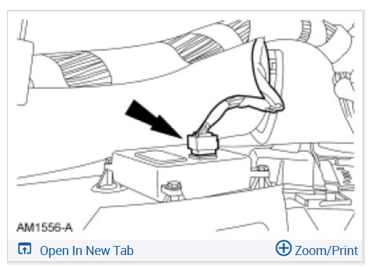
There are a few tests that can be done to verify if it's the actuator or the control unit. However being a barn find it could also be wiring damage from rodents and the testing may not show that. A code 24 is showing that the control isn't seeing feedback from the position sensor on the actuator. There are two systems available for that vehicle, the automatic one (you dial in a temperature and it does the rest) and the manual one where you move the knob for hot and cold. I'm guessing it is the automatic version, that uses two different voltages to the actuator. one is battery voltage that moves the actual motor, the other is a 5 volt circuit that the system monitors to tell the blend door position. There is a complete battery of tests that can be run to determine the state of the actuator. However the easiest testing involves having a scan tool that can talk to the HVAC controller and lets you monitor the actual blend door position. With that you remove the trim to access the rear of the HVAC controller and use a couple jumpers to battery voltage to move the actuator motor itself while watching the position voltage. MUCH faster than the OE tests but requires a good scan tool. (Being this is a Ford product you might want to look at a program called FORScan
https://forscan.org/home.html and the dongle they recommend. Running that on a windows computer gives you more abilities than even a factory scan tool.)
Now having said that could you verify if you have the auto or manual system and what you have for test equipment? Like a good multimeter or? I'll copy the OE tests that use a meter although it and my tests both require access to the connection on the rear of the HVAC control unit. These suppose that you have the automatic system -
Pinpoint Test C- DTC B1249 (aka the 24 code you have)
Normal Operation
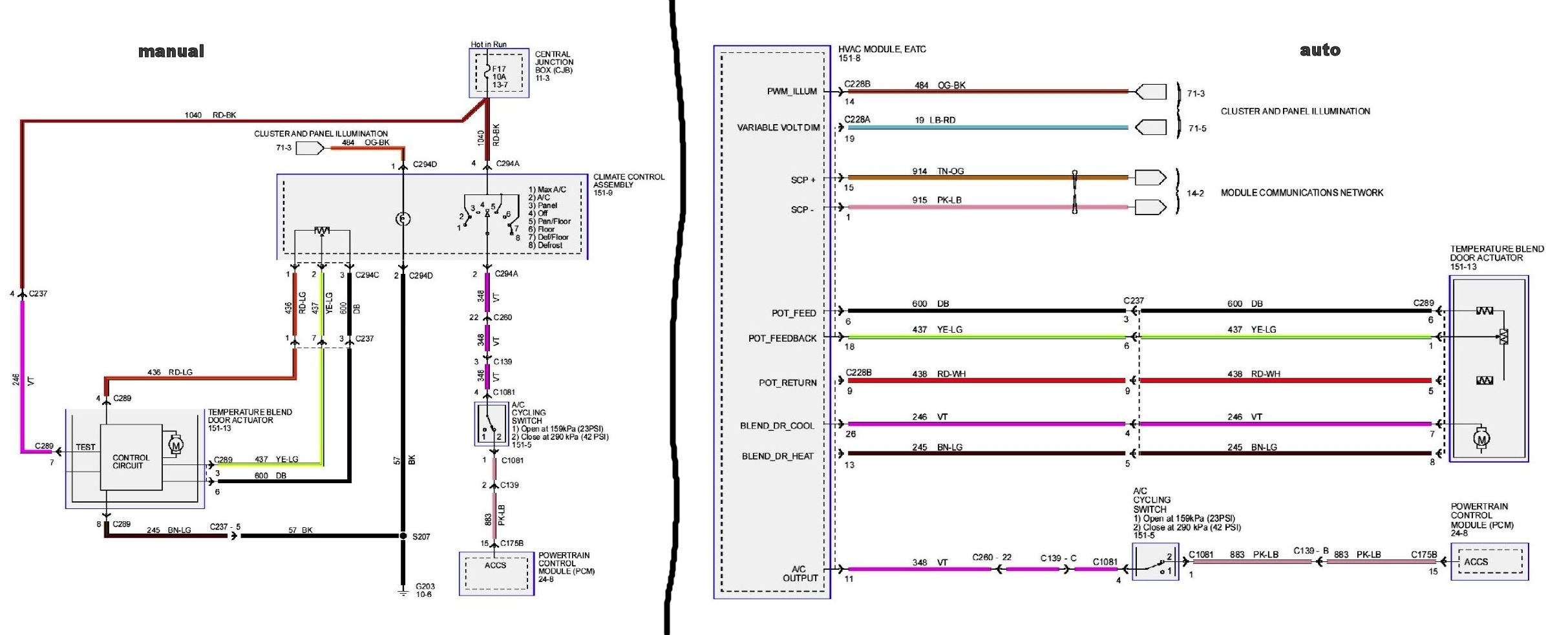
Under normal operation, to rotate the temperature blend door actuator, the HVAC module supplies voltage and ground to the temperature blend door actuators through the door actuator motor circuits. To reverse the temperature blend door actuator rotation, the HVAC module reverses the voltage and ground circuits. (These are the Brown w/light green and Violet wires in the attached image)
The temperature blend door actuator feedback resistors are supplied a ground from the HVAC module by the temperature blend door actuator return circuits and a 5-volt reference voltage on the temperature blend door actuator reference circuits. The HVAC module reads the voltage on the temperature blend door actuator feedback circuits to determine the temperature blend door actuator position by the position of the actuator feedback resistor wiper arm. (These are the Dark Blue, Yellow w/light green and Red w/white wires)
During an actuator calibration cycle, the HVAC module drives the temperature blend door until the door reaches both internal stops in the HVAC case. If the temperature blend door is temporarily obstructed or binding during a calibration cycle, the HVAC module may interpret this as the actual end of travel for the door. When this condition occurs and the HVAC module commands the actuator to its end of travel, the airflow may not be the expected temperature. (Happens a lot if there were rodents involved)
- DTC B1249 (AKA 24) (Blend Door Failure) - The module senses no change in actuator feedback voltage when the actuator motor has been energized. (IE no changes on the three wires on the feedback)
This pinpoint test is intended to diagnose the following:
- Wiring, terminals or connectors
- Temperature blend door actuator
- HVAC module
- Stuck or bound linkage or door
You will see that some of these tests use the same images for the connections, that is because many are for an open or closed test with resistance numbers and voltages and use the same connections for those tests.
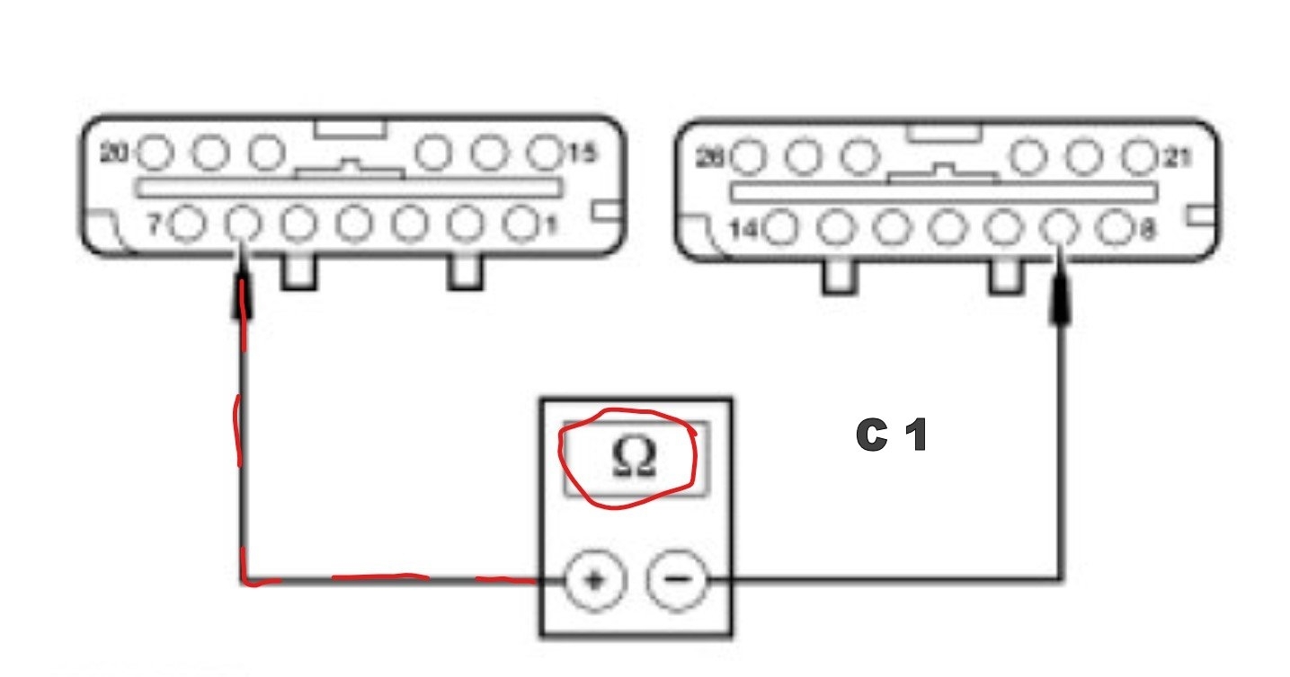
C1 CHECK THE FEEDBACK POTENTIOMETER TOTAL RESISTANCE
- Ignition OFF.
- Disconnect: HVAC Module C228A.
- Disconnect: HVAC Module C228B.
- Measure the resistance between HVAC module C228A-6, circuit 600 (DB), harness side and HVAC module C228B-9, circuit 438 (RD/WH), harness side. (These are the connectors on the HVAC control)
ATTACHED IMAGE C 1
- Is the resistance between 5,000 and 6,000 ohms?
Yes
GO to C2.
No
If the resistance is greater than 6,000 ohms, GO to C4.
If the resistance is less than 5,000 ohms, GO to C5.
________________
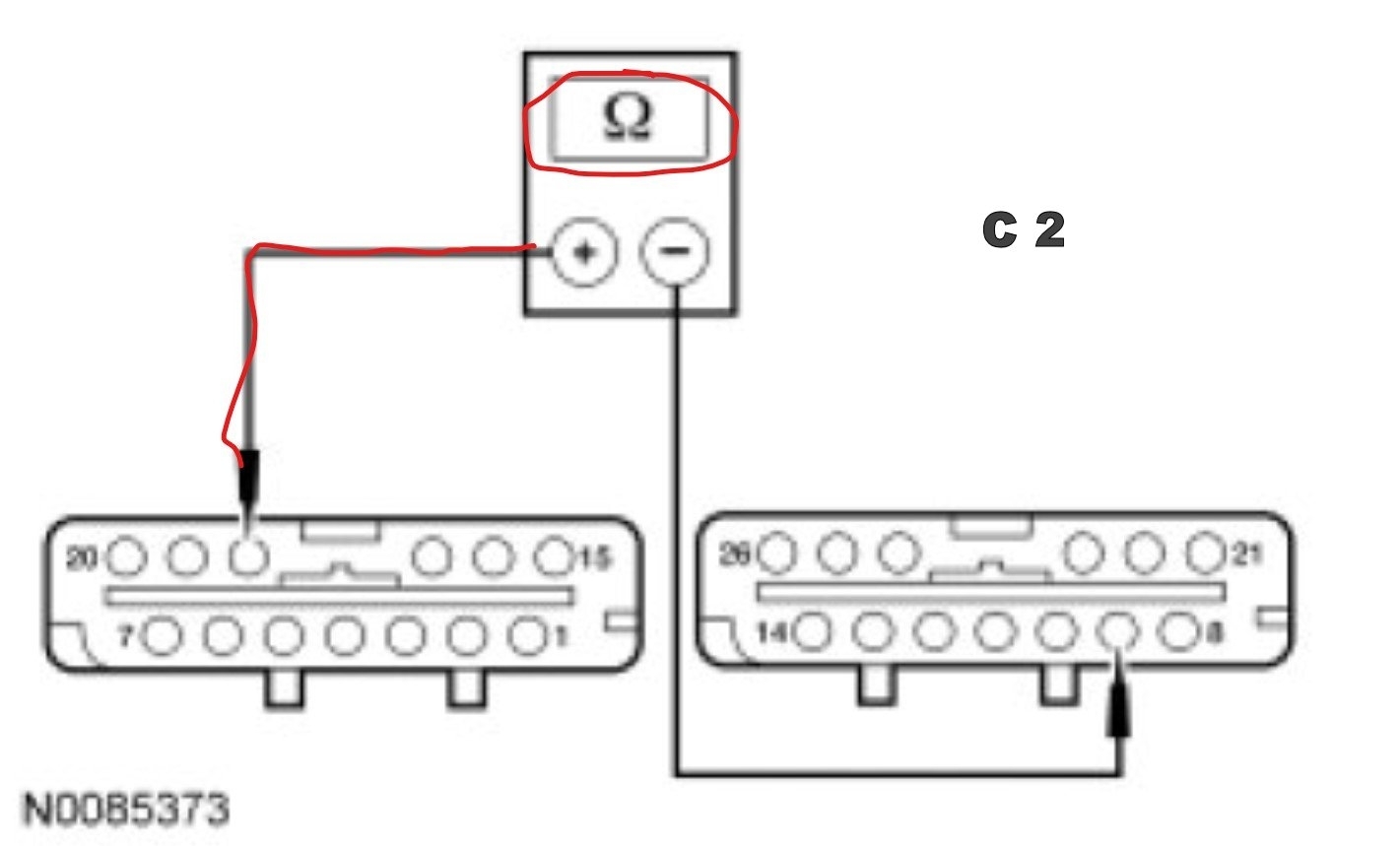
C2 CHECK POTENTIOMETER LOW-SIDE RESISTANCE
- Measure the resistance between HVAC module C228A-18, circuit 437 (YE/LG), harness side and HVAC module C228B-9, circuit 438 (RD/WH), harness side.
ATTACHED IMAGE C 2
- Is the resistance between 250 and 3,000 ohms?
Yes
GO to C3.
No
If the resistance is greater than 3,000 ohms, GO to C6.
If the resistance is less than 250 ohms, GO to C7.
________________
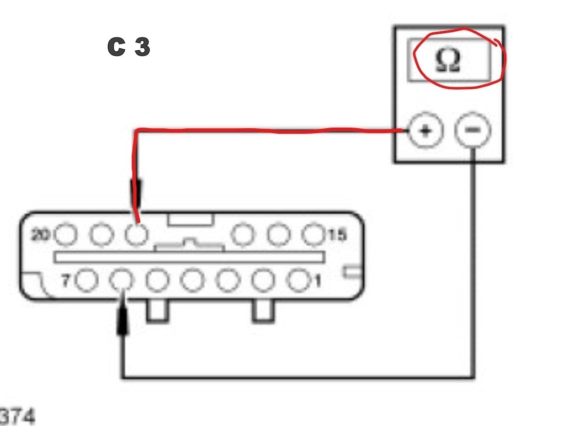
C3 CHECK POTENTIOMETER HIGH-SIDE RESISTANCE
- Measure the resistance between HVAC module C228A-6, circuit 600 (DB), harness side and HVAC module C228A-18, circuit 437 (YE/LG), harness side.
ATTACHED IMAGE C 3
- Is the resistance between 3,000 and 6,000 ohms?
Yes
GO to C9.
No
If the resistance is greater than 6,000 ohms, GO to C14.
If the resistance is less than 3,000 ohms, GO to C8.
-------------------------------------------------
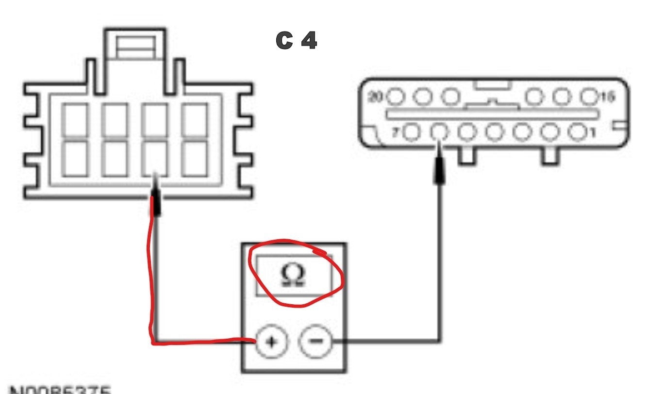
C4 CHECK CIRCUITS 600 (DB) AND 438 (RD/WH) FOR AN OPEN
NOTE: Access to the connector in the following step is difficult. Before performing this step, visually inspect the actuator and its harness for obvious damage. If no damage is evident, proceed with the test.
- Disconnect: Temperature Blend Door Actuator C289.
- Measure the resistance between HVAC module C228A-6, circuit 600 (DB), harness side and temperature blend door actuator C289-6, circuit 600 (DB), harness side.
ATTACHED IMAGE C 4
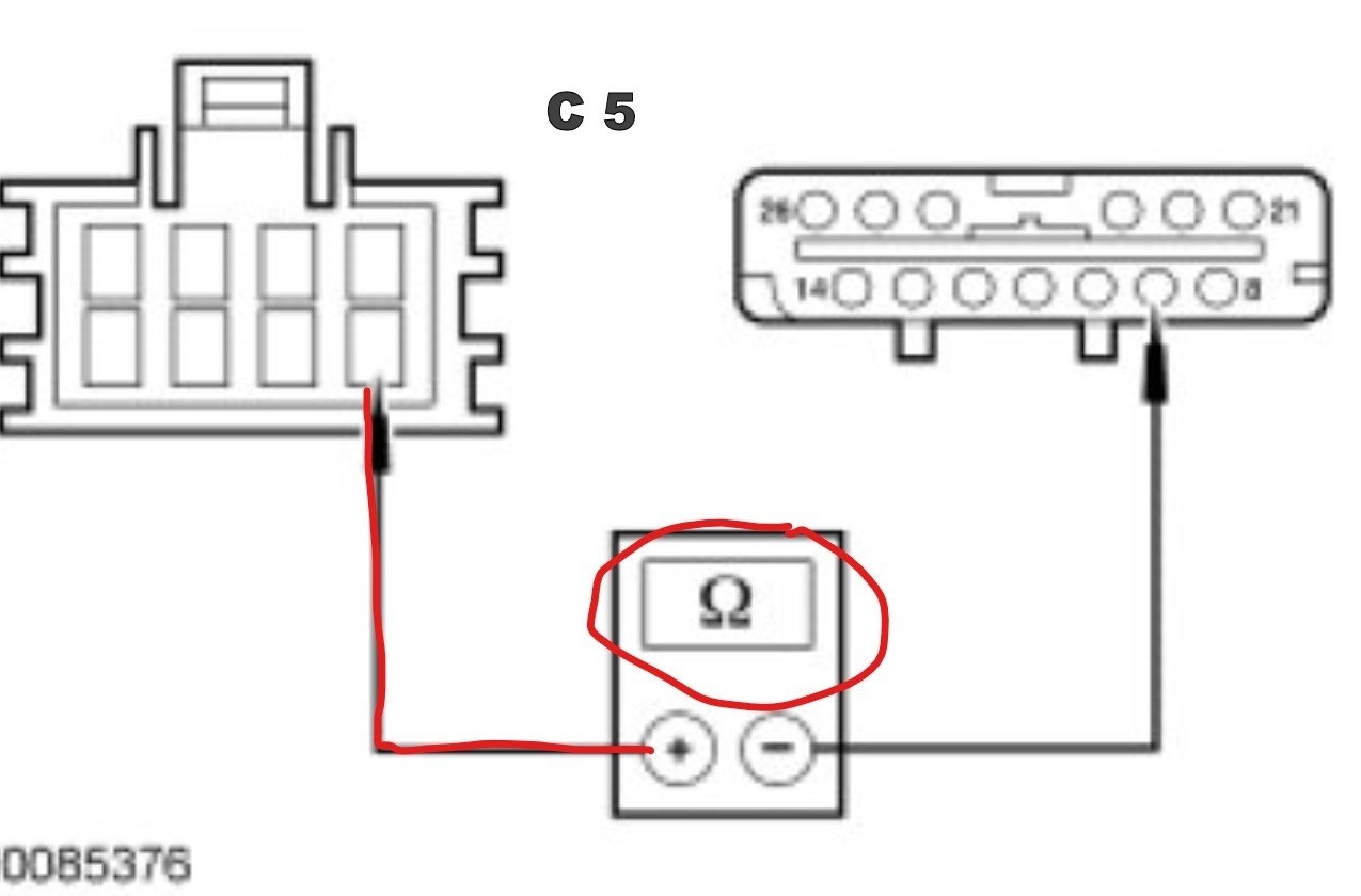
- Measure the resistance between HVAC module C228B-9, circuit 438 (RD/WH), harness side and temperature blend door actuator C289-5, circuit 438 (RD/WH), harness side.
ATTACHED IMAGE C 5
- Are the resistances less than 5 ohms?
Yes
GO to C14.
No
REPAIR the affected circuit for an open. CLEAR the DTCs. REPEAT the self-test. TEST the system for normal operation.
-------------------------------------------------
C5 CHECK CIRCUITS 438 (RD/WH) AND 600 (DB) FOR A SHORT TOGETHER
NOTE: Access to the connector in the following step is difficult. Before performing this step, visually inspect the actuator and its harness for obvious damage. If no damage is evident, proceed with the test.
- Disconnect: Temperature Blend Door Actuator C289.
- Measure the resistance between HVAC module C228B-9, circuit 438 (RD/WH), harness side and HVAC module C228A-6, circuit 600 (DB), harness side.
ATTACHED IMAGE C 1
- Is the resistance greater than 10,000 ohms?
Yes
GO to C14.
No
REPAIR circuits 438 (RD/WH) for a short to circuit 600 (DB). CLEAR the DTCs. REPEAT the self-test. TEST the system for normal operation.
-------------------------------------------------
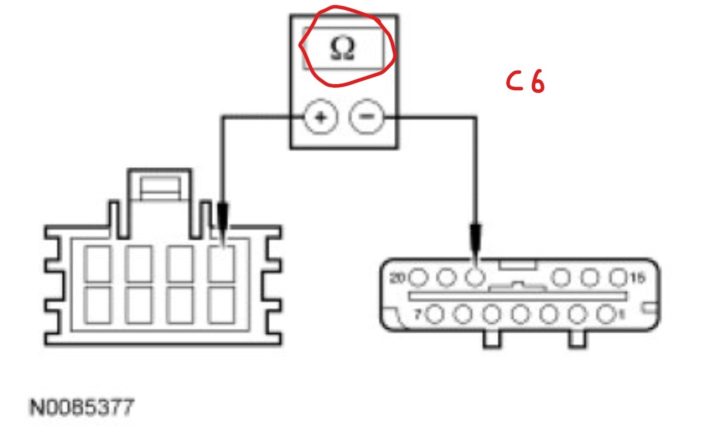
C6 CHECK CIRCUIT 437 (YE/LG) FOR AN OPEN
NOTE: Access to the connector in the following step is difficult. Before performing this step, visually inspect the actuator and its harness for obvious damage. If no damage is evident, proceed with the test.
- Disconnect: Temperature Blend Door Actuator C289.
- Measure the resistance between HVAC module C228A-18, circuit 437 (YE/LG), harness side and temperature blend door actuator C289-1, circuit 437 (YE/LG), harness side.
ATTACHED IMAGE C 6
- Is the resistance less than 5 ohms?
Yes
GO to C14.
No
REPAIR circuit 437 (YE/LG) for an open. CLEAR the DTCs. REPEAT the self-test. TEST the system for normal operation.
-------------------------------------------------
C7 CHECK CIRCUITS 438 (RD/WH) AND 437 (YE/LG) FOR A SHORT TOGETHER
NOTE: Access to the connector in the following step is difficult. Before performing this step, visually inspect the actuator and its harness for obvious damage. If no damage is evident, proceed with the test.
- Disconnect: Temperature Blend Door Actuator C289.
- Measure the resistance between HVAC module C228B-9, circuit 438 (RD/WH), harness side and HVAC module C228A-18, circuit 437 (YE/LG), harness side.
ATTACHED IMAGE C 2
- Is the resistance greater than 10,000 ohms?
Yes
GO to C14.
No
REPAIR circuits 438 (RD/WH) and 437 (YE/LG) for a short together. CLEAR the DTCs. REPEAT the self-test. TEST the system for normal operation.
-------------------------------------------------
C8 CHECK CIRCUIT 437 (YE/LG) FOR A SHORT TO CIRCUIT 436 (RD/LG) OR 600 (DB)
NOTE: Access to the connector in the following step is difficult. Before performing this step, visually inspect the actuator and its harness for obvious damage. If no damage is evident, proceed with the test.
- Disconnect: Temperature Blend Door Actuator C289.
- Measure the resistance between HVAC module C228A-6, circuit 600 (DB), harness side and HVAC module C228A-18, circuit 437 (YE/LG), harness side.
ATTACHED IMAGE C 3
- Is the resistance greater than 10,000 ohms?
Yes
GO to C14.
No
REPAIR circuits 437 (YE/LG) for a short to circuit 600 (DB). CLEAR the DTCs. REPEAT the self-test. TEST the system for normal operation.
-------------------------------------------------
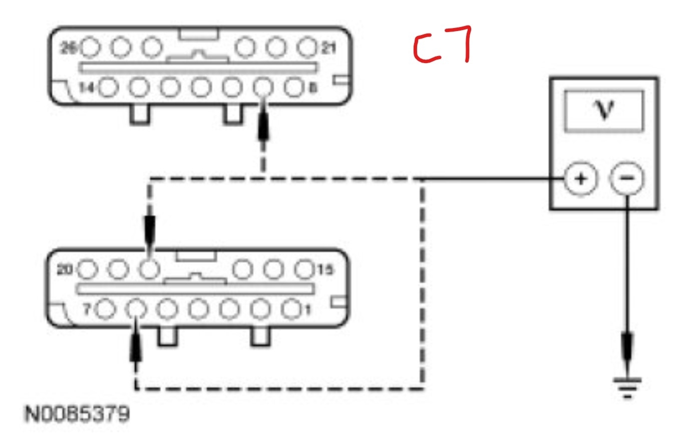
C9 CHECK CIRCUITS 600 (DB), 437 (YE/LG) AND 438 (RD/WH) FOR A SHORT TO VOLTAGE
- Ignition ON.
- Measure the voltage between ground and:
- HVAC module C228A-6, circuit 600 (DB), harness side.
- HVAC module C228A-18, circuit 437 (YE/LG), harness side.
- HVAC module C228B-9, circuit 438 (RD/WH), harness side.
ATTACHED IMAGE C 7
- Is any voltage present?
Yes
REPAIR the affected circuit for a short to voltage. CLEAR the DTCs. REPEAT the self-test. TEST the system for normal operation.
No
GO to C10.
-------------------------------------------------
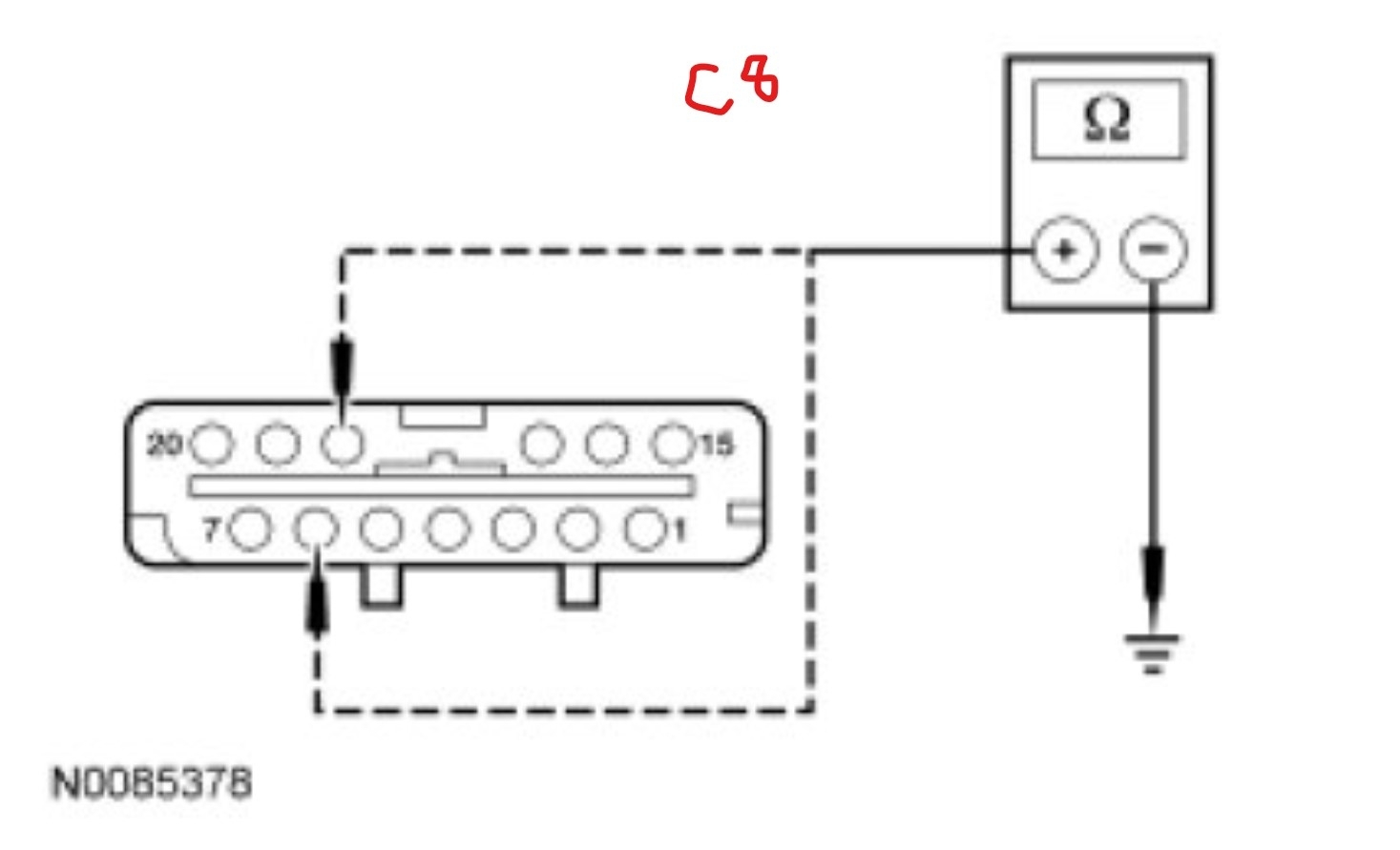
C10 CHECK CIRCUITS 600 (DB) AND 437 (YE/LG) FOR A SHORT TO GROUND
- Measure the resistance between ground and:
- HVAC module C228A-6, circuit 600 (DB), harness side.
- HVAC module C228A-18, circuit 437 (YE/LG), harness side.
ATTACHED IMAGE C 8
- Are the resistances greater than 10,000 ohms?
Yes
INSPECT for a broken door or linkage. If no condition is found, GO to C11.
No
REPAIR circuit 600 (DB) or 437 (YE/LG) for a short to ground. CLEAR the DTCs. REPEAT the self-test. TEST the system for normal operation.
-------------------------------------------------
C11 CHECK THE BLEND DOOR ACTUATOR OPERATION
NOTE: If a jumper fuse opens while carrying out this test step, repair the circuit(s) for a short.
- With the fused jumper connections made as directed below, measure the resistance between HVAC module C228A-18, circuit 437 (YE/LG), harness side and HVAC module C228B-9, circuit 438 (RD/WH), harness side.
ATTACHED IMAGE C 2
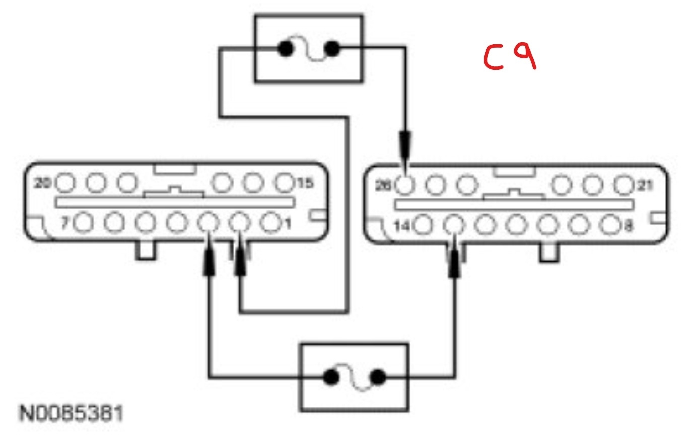
- Connect a fused jumper wire between HVAC module C228B-26, circuit 246 (VT), harness side and HVAC module C228A-2, circuit 1566 (RD/YE), harness side. Connect a second fused jumper wire between HVAC module C228B-13, circuit 245 (BN/LG), harness side and HVAC module C228A-3, circuit 57 (BK), harness side.
ATTACHED IMAGE C 9
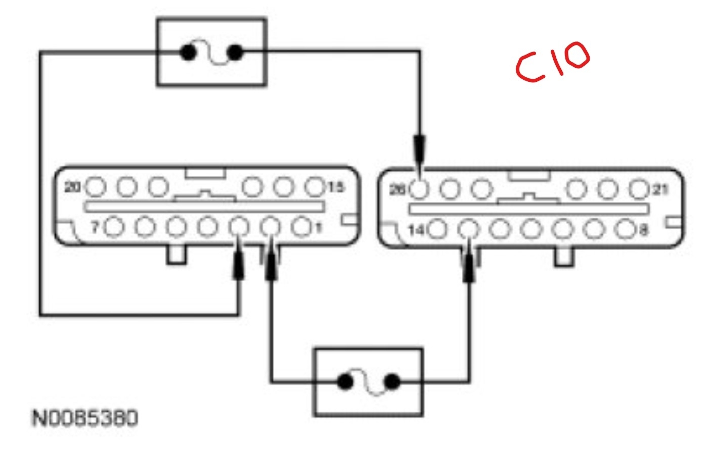
- Connect a fused jumper wire between HVAC module C228B-13, circuit 245 (BN/LG), harness side and HVAC module C228A-2, circuit 1566 (RD/YE), harness side. Connect a second fused jumper wire between HVAC module C228B-26, circuit 246 (VT), harness side and HVAC module C228A-3, circuit 57 (BK), harness side.
ATTACHED IMAGE C 10
- Does the resistance smoothly increase and/or decrease when the jumpers are connected?
Yes
INSPECT for binding or broken door and linkage. If no condition is found, GO to C15.
No
GO to C12.
-------------------------------------------------
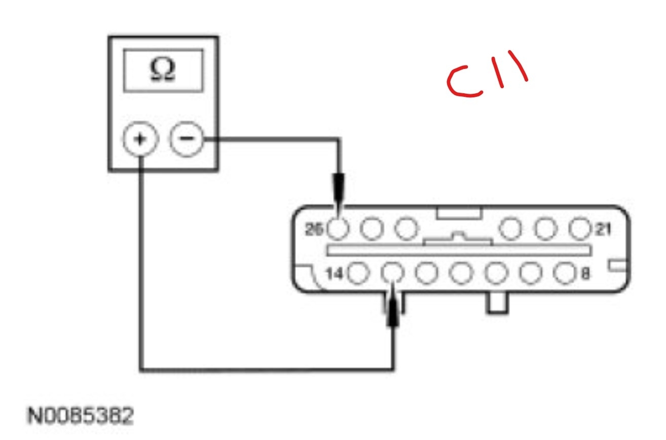
C12 CHECK THE ACTUATOR MOTOR DRIVE CIRCUITS
- Ignition OFF.
- Measure the resistance between HVAC module C228B-13, circuit 245 (BN/LG), harness side and HVAC module C228B-26, circuit 246 (VT), harness side.
ATTACHED IMAGE C 11
- Is the resistance approximately 20-80 ohms?
Yes
INSPECT for binding or broken door and linkage. If no condition is found, INSTALL a new door actuator. CLEAR the DTCs. REPEAT the self-test. TEST the system for normal operation.
No
GO to C13.
-------------------------------------------------
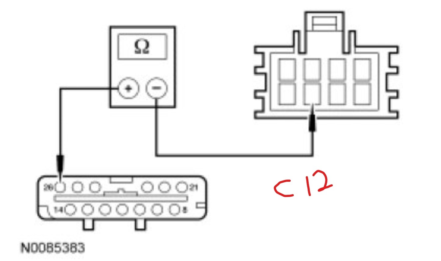
C13 CHECK CIRCUITS 246 (VT) AND 245 (BN/LG) FOR AN OPEN
- Disconnect: Temperature Blend Door Actuator C289.
- Measure the resistance between HVAC module C228B-26, circuit 246 (VT), harness side and temperature blend door actuator C289-7, circuit 246 (VT), harness side.
ATTACHED IMAGE C 12
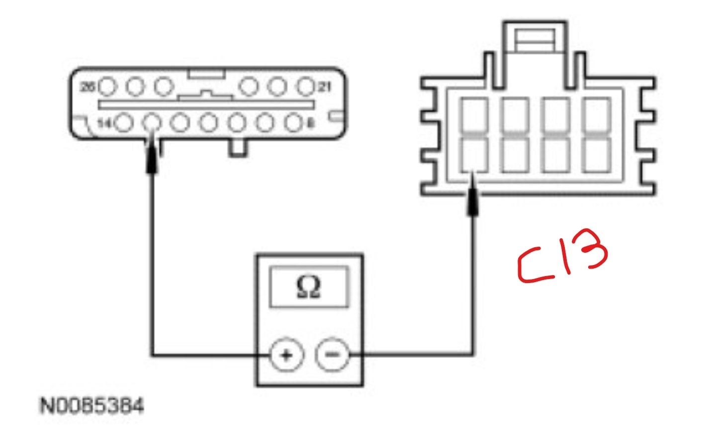
- Measure the resistance between HVAC module C228B-13, circuit 245 (BN/LG), harness side and temperature blend door actuator C289-8, circuit 245 (BN/LG), harness side.
ATTACHED IMAGE C 13
- Are the resistances less than 5 ohms?
Yes
GO to C14.
No
REPAIR the affected circuit for an open. CLEAR the DTCs. REPEAT the self-test. TEST the system for normal operation.
-------------------------------------------------
C14 CHECK THE ACTUATOR CONNECTION
- Disconnect the actuator connector.
- Check for:
- corrosion.
- pushed-out terminals.
- damaged terminals.
- Connect and correctly seat the actuator connector.
- Clear the DTCs.
- Operate the system and verify the concern is still present.
- Is the concern still present?
Yes
INSTALL a new temperature blend door actuator. If a new actuator is installed, CONNECT the actuator electrical connectors before the HVAC module connectors. This will allow the new actuator to be calibrated when the HVAC module is reconnected.
CLEAR the DTCs. REPEAT the self-test. TEST the system for normal operation.
No
The system is operating correctly at this time. The concern may have been caused by a loose or corroded connector. CLEAR the DTCs. TEST the system for normal operation.
-------------------------------------------------
C15 MODULE ACTUATOR POSITION CALIBRATION Last step
NOTE: The purpose of the module actuator position calibration is to allow the HVAC module to reinitialize and calibrate the actuator stop points. To carry out the calibration, follow the steps below.
- Ignition OFF.
- Inspect the module connectors for:
- corrosion.
- pushed-out terminals.
- damaged terminals.
- Connect and correctly seat all the HVAC module connectors.
- Ignition ON.
- Clear the DTCs.
- Select any position except OFF.
- NOTE: The HVAC module will now initialize and calibrate the actuators. Calibration of the actuators will take approximately 30 seconds.
- Operate the system and verify the concern is still present.
- Is the concern still present?
Yes
INSTALL a new HVAC module. TEST the system for normal operation.
No
The system is now operating correctly at this time. The concern may have been caused by a foreign object in the HVAC case or temporary binding that restricted actuator door travel. CHECK any actuator external linkage. If condition recurs, INSPECT actuator linkage and door for binding and CHECK HVAC case for foreign objects.
Images (Click to enlarge)
Dec 11, 2025 at 11:36 AM