Sounds like a plan. Once you replace it, let me know what you find.
__________________
I don't know if you want it but here are the diagnostics for the codes.
___________________
1997 Nissan-Datsun Truck D21 Hardbody XE 2WD L4-2389cc 2.4L SOHC MFI (KA24E)
P0100
Vehicle ALL Diagnostic Trouble Codes ( DTC ) Testing and Inspection P Code Charts P0100
P0100
pic 1
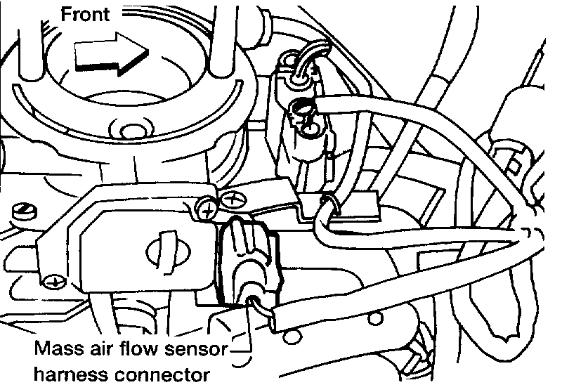
COMPONENT DESCRIPTION
The mass air flow sensor is placed in the stream of intake air. It measures the intake flow rate by measuring a part of the entire intake flow. It consists of a hot wire that is supplied with electric current from the ECM. The temperature of the hot wire is controlled by the ECM a certain amount. The heat generated by the hot wire is reduced as the intake air flows around it. The more air, the greater the heat loss.
Therefore, the ECM must supply more electric current to the hot wire as air flow increases. This maintains the temperature of the hot wire. The ECM detects the air flow by means of this current change.
Pic 2
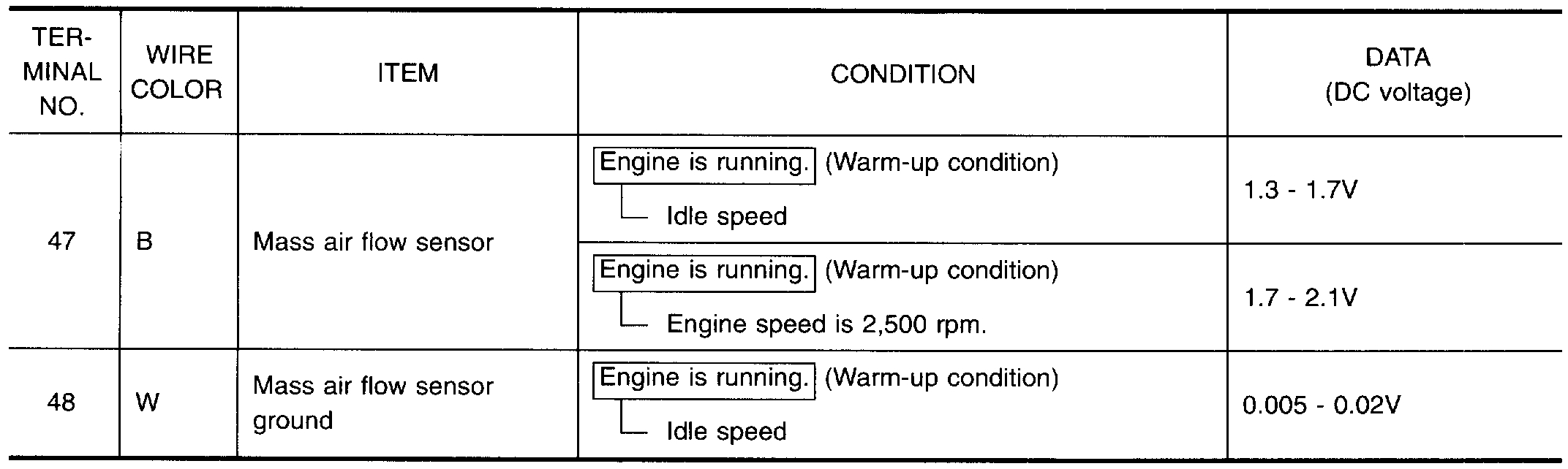
ECM TERMINALS AND REFERENCE VALUE
Specification data are reference values and are measured between each terminal and (43) (ECCS ground).
Pic 3
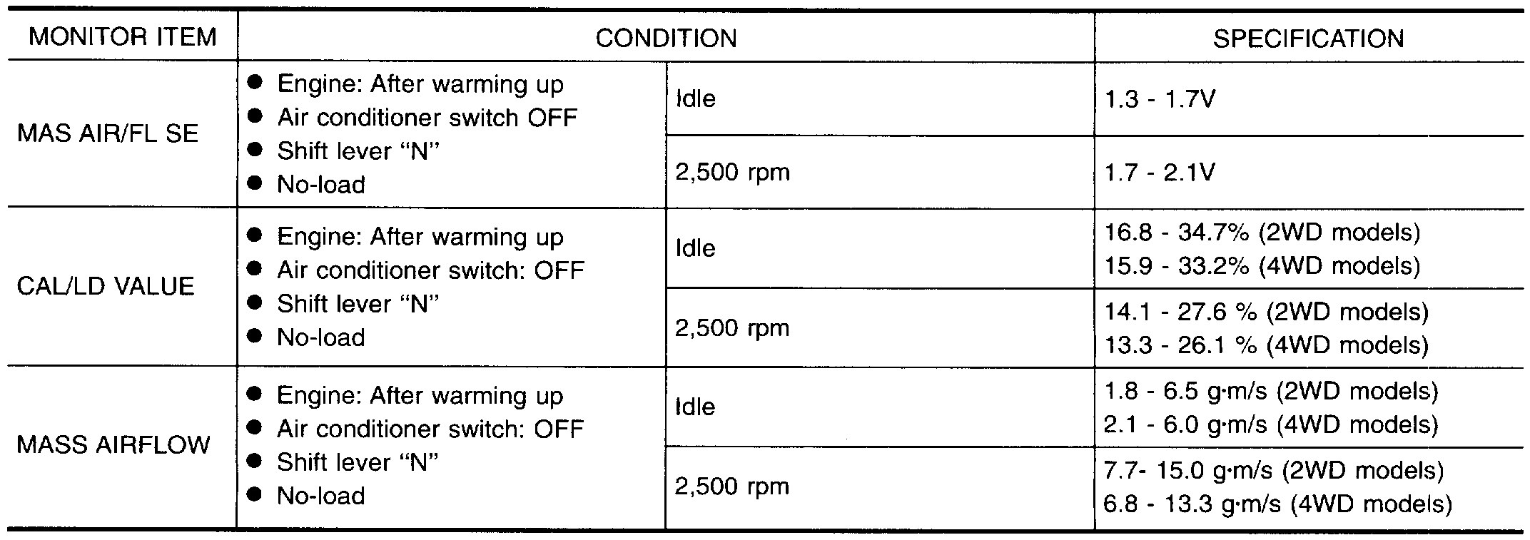
CONSULT REFERENCE VALUE IN DATA MONITOR MODE
Specification data are reference values.
Pic 4
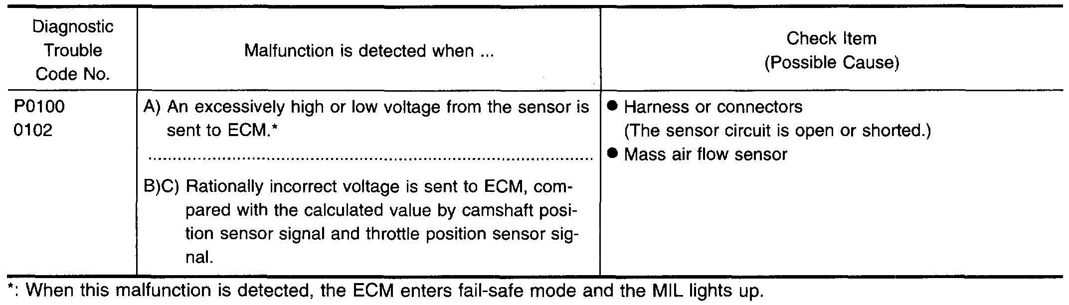
OPEN BOARD DIAGNOSIS LOGIC
Engine operating condition in fail-safe mode
Engine speed will not rise more than 2,400 rpm due to the fuel cut.
DIAGNOSTIC TROUBLE CODE CONFIRMATION PROCEDURE
Perform "Procedure for malfunction A" first. If the 1st trip DTC cannot be confirmed, perform "Procedure for malfunction B". If there is no problem on "Procedure for malfunction B", perform "Procedure for malfunction C", "OVERALL FUNCTION CHECK".
Procedure for Malfunction A
With CONSULT
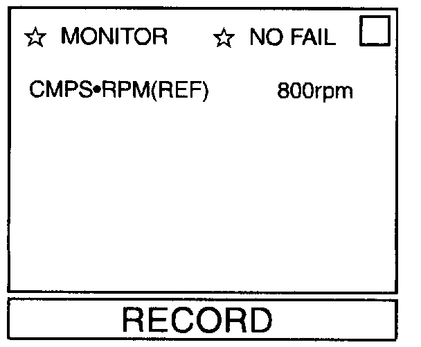
(1)Turn ignition switch "ON" and wait at least 6 seconds.
Pic 5
(2)Select "DATA MONITOR" mode with CONSULT.
(3)Start engine and wait at least 3 seconds.
OR
With GST
(1)Turn ignition switch "ON" and wait at least 6 seconds.
(2)Start engine and wait at least 3 seconds.
(3)Select "MODE 7" with GST.
OR
NO TOOLS
(1)Turn ignition switch "ON" and wait at least 6 seconds.
(2)Start engine and wait at least 3 seconds.
(3)Turn ignition switch "OFF", wait at least 7 seconds and then turn "ON".
(4)Perform "Diagnostic Test Mode II (Self-diagnostic results)" with ECM.
Procedure for Malfunction B
With CONSULT
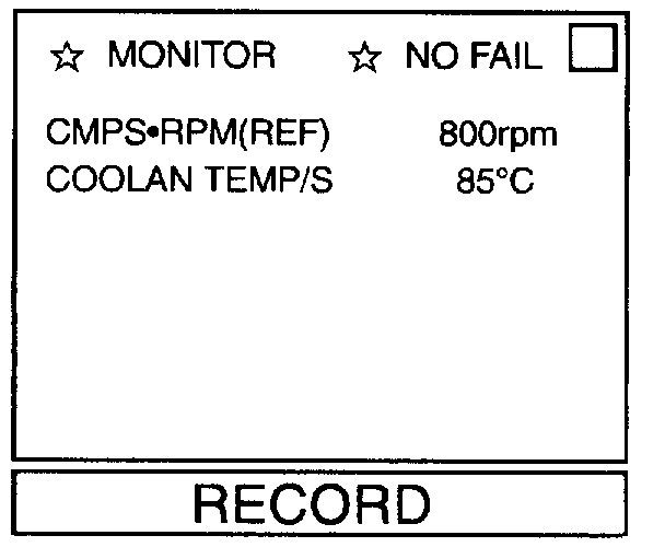
(1)Turn ignition switch "ON".
Pic 6
(2)Select "DATA MONITOR" mode with CONSULT.
(3)Start engine and warm it up sufficiently.
(4)Run engine for at least 10 seconds at idle speed.
OR
With GST
(1)Turn ignition switch "ON".
(2)Start engine and warm it up sufficiently.
(3)Run engine for at least 10 seconds at idle speed.
(4)Select "MODE 7" with GST.
OR
NO TOOLS
(1)Turn ignition switch "ON".
(2)Start engine and warm it up sufficiently.
(3)Run engine for at least 10 seconds at idle speed.
(4)Turn ignition switch "OFF", wait at least 7 seconds and then turn "ON".
(5)Perform "Diagnostic Test Mode II (Self-diagnostic results)" with ECM.
OVERALL FUNCTION CHECK
Use this procedure to check the overall function of mass air flow sensor. During this check a 1st trip DTC might not be confirmed.
Procedure for Malfunction C
With CONSULT
(1)Turn ignition switch "ON".
(2)Start engine and warm it up sufficiently.
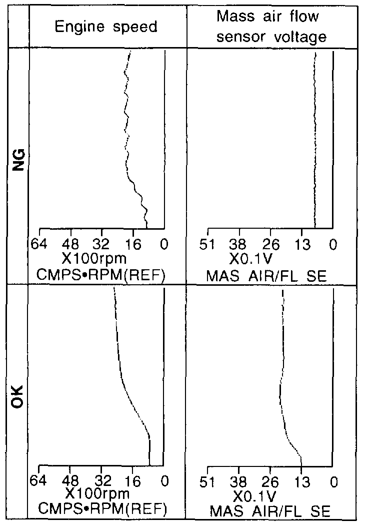
(3)Select "DATA MONITOR" mode with CONSULT.
Pic 7
(4)Check the voltage of mass air flow sensor with "DATA MONITOR".
(5)Check for linear voltage rise in response to increases to about 4,000 rpm in engine speed.
OR
With GST
(1)Turn ignition switch "ON".
(2)Start engine and warm it up sufficiently.
Pic 8
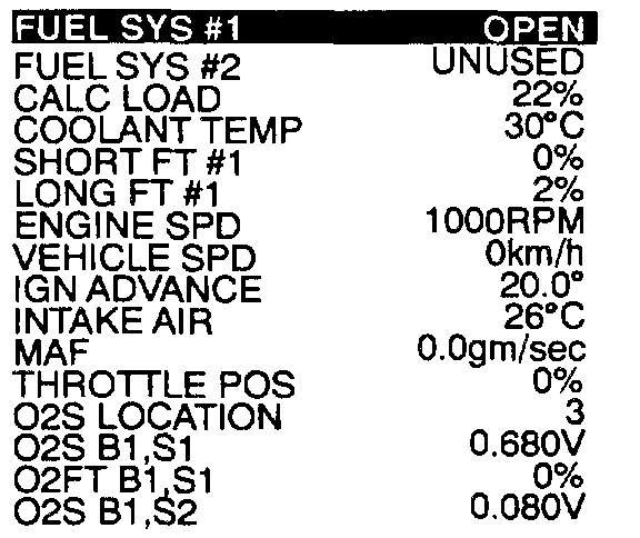
(3)Select "MODE 1" with GST.
(4)Check the mass air flow with "MODE 1".
(5)Check for linear mass air flow rise in response to increases to about 4,000 rpm in engine speed.
OR
NO TOOLS
(1)Turn ignition switch "ON".
(2)Start engine and warm it up sufficiently.
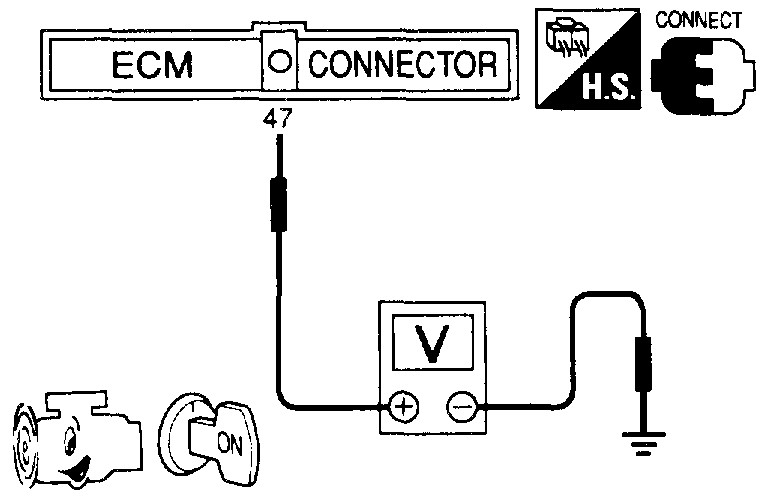
Pic 9
(3)Check the voltage between ECM terminal (47) and ground.
(4)Check for linear voltage rise in response to increases to about 4,000 rpm in engine speed.
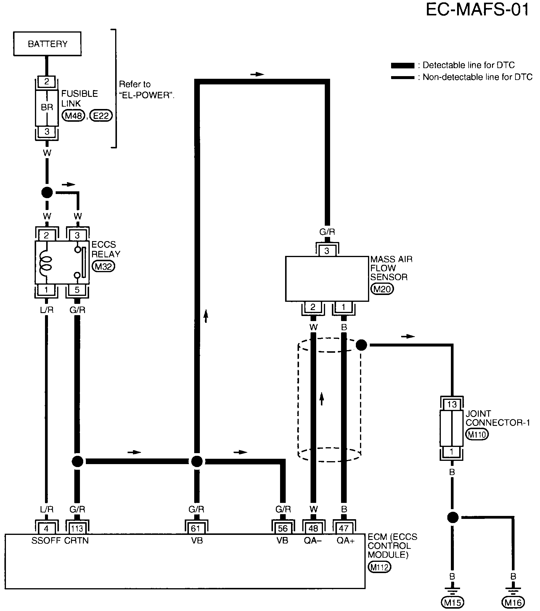
EC-MAFS-01 Mass Air Flow Sensor (MAFS) (DTC P0100)
Pic 10
WIRING DIAGRAM
pic 11
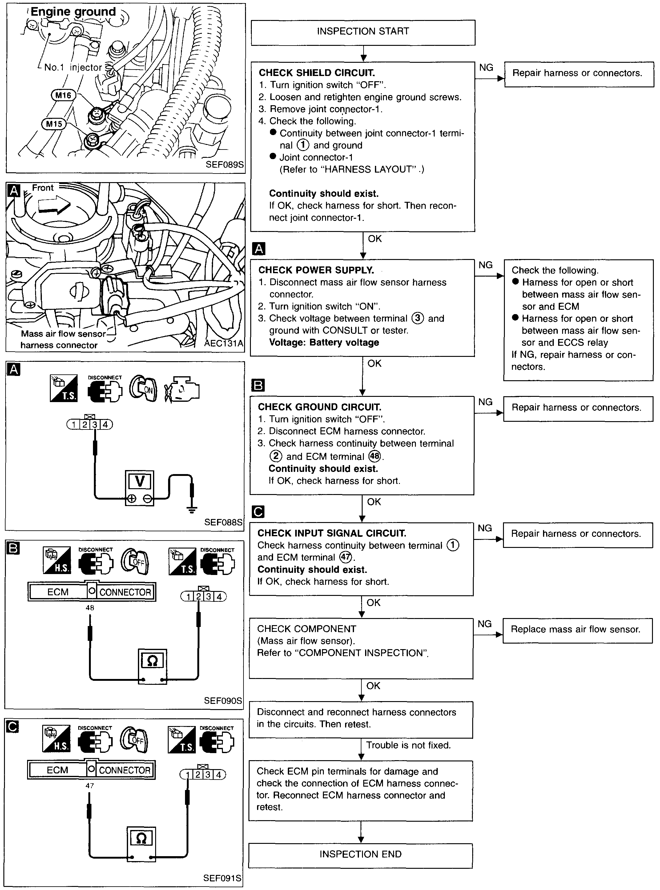
DIAGNOSTIC PROCEDURE
COMPONENT INSPECTION
Mass Air Flow Sensor
1. Turn ignition switch "ON".
2. Start engine and warm it up sufficiently.
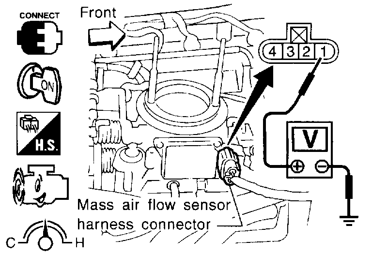
Pic 12
3. Check voltage between terminal 1 and ground.
Conditions / Voltage, V
Ignition switch "ON" (Engine stopped.) / Less than 1.0
Idle (Engine is warmed-up sufficiently.) / 1.3 - 1.7
2,500 rpm / 1.7 - 2.3
Idle to about 4,000 rpm / 1.3 - 1.7 to Approx. 4.0
*: Check for linear voltage rise in response to increases to about 4,000 rpm in engine speed.
Pic 13
4. If NG, remove mass air flow sensor from air duct. Check hot wire for damage or dust.
____________________________________________________________________________________
1997 Nissan-Datsun Truck D21 Hardbody XE 2WD L4-2389cc 2.4L SOHC MFI (KA24E)
P0120
Vehicle ALL Diagnostic Trouble Codes ( DTC ) Testing and Inspection P Code Charts P0120
P0120
pic 14
pic 15
COMPONENT DESCRIPTION
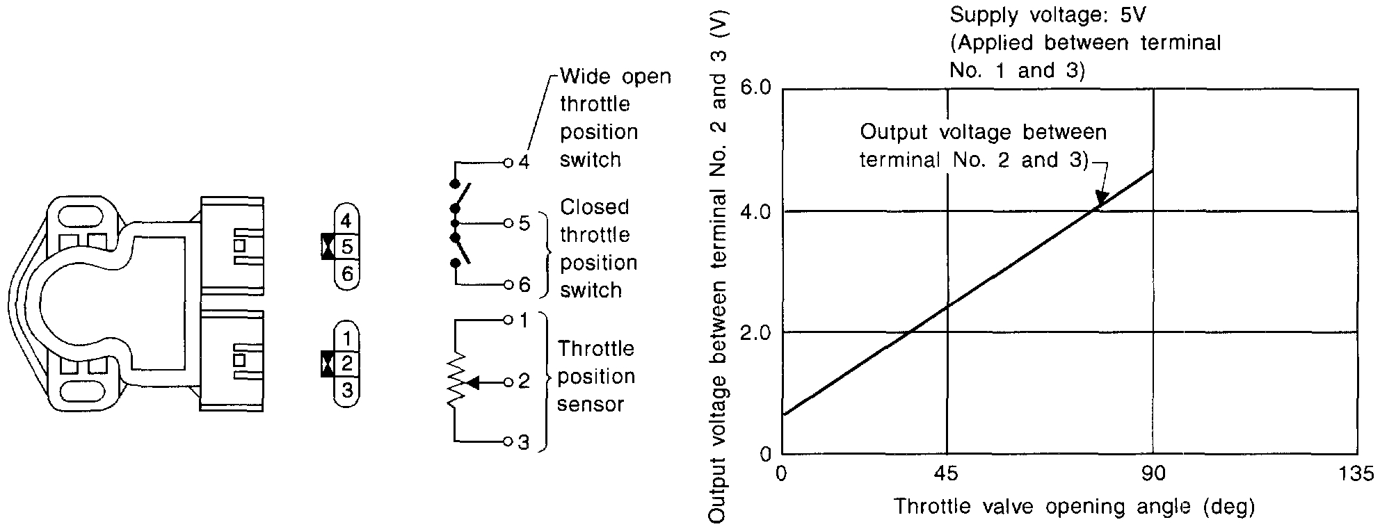
The throttle position sensor responds to the accelerator pedal movement. This sensor is a kind of potentiometer which transforms the throttle position into output voltage and emits the voltage signal to the ECM. In addition, the sensor detects the opening and closing speed of the throttle valve and feeds the voltage signal to the ECM.
Idle position of the throttle valve is determined by the ECM receiving the signal from the throttle position sensor. This controls engine operation such as fuel cut. The throttle position sensor unit contains a built-in "Wide open and closed throttle position switch".
Pic 16
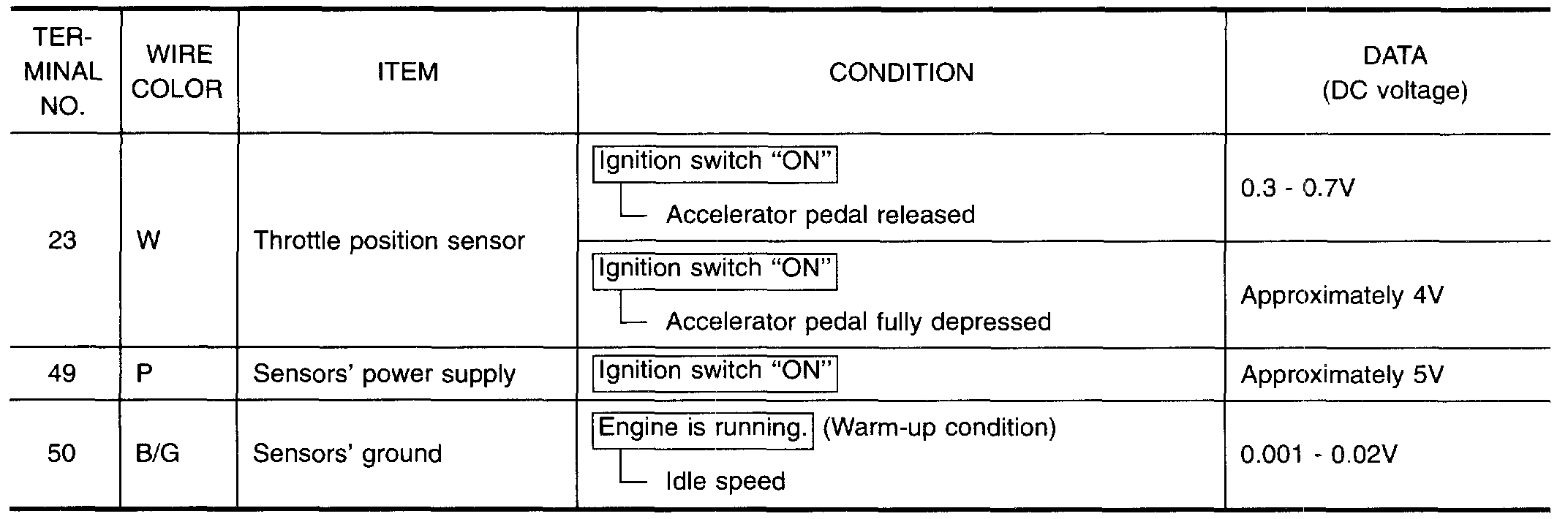
ECM TERMINALS AND REFERENCE VALUE
Specification data are reference values and are measured between each terminal and (43) (ECCS ground).
Pic 17
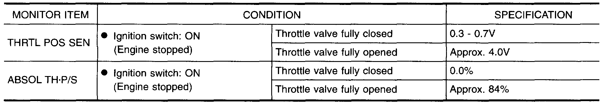
CONSULT REFERENCE VALUE IN DATA MONITOR MODE
Specification data are reference values
pic 18
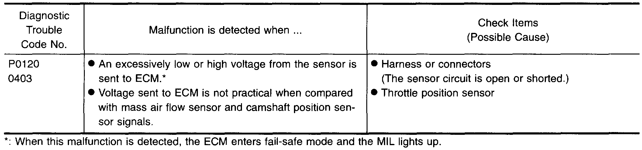
ON BOARD DIAGNOSIS LOGIC
Engine operating condition in fail-safe mode
Throttle position will be determined based on the injected fuel amount and the engine speed.
Therefore, acceleration will be poor.
Condition / Driving Condition
When Engine is Idling / Normal
When accelerating / Poor accelerating
OVERALL FUNCTION CHECK
Use this procedure to check the overall function of the throttle position sensor circuit. During this check, a 1st trip DTC might not be confirmed.
With CONSULT
(1)Start engine and warm it up sufficiently.
(2)Turn ignition switch "OFF" and wait at least 7 seconds.
(3)Turn ignition switch "ON".
Pic 19
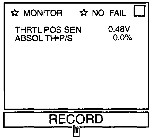
(4)Select "MANU TRIG" and "HI SPEED" in "DATA MONITOR" mode with CONSULT
(5)Select "THRTL POS SEN" and "AE3SOL TH.P/S" in "DATA MONITOR" mode with CONSULT.
(6)Press RECORD on CONSULT SCREEN at the same time accelerator pedal is depressed.
Pic 20
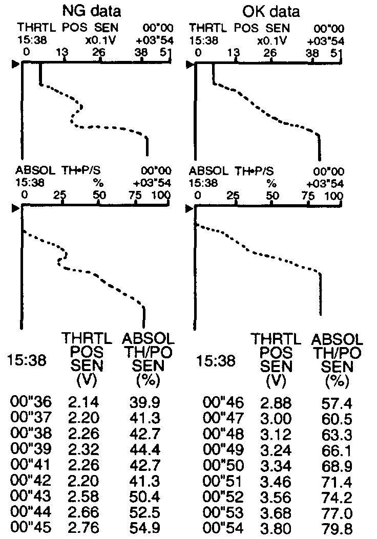
(7)Print out the recorded data and check the following:
- The voltage when accelerator pedal fully released is 0.3 - 0.7V.
- The voltage rise is linear in response to accelerator pedal depression.
- The voltage when accelerator pedal fully depressed is approximately 4V.
OR
Without CONSULT
(1)Start engine and warm it up sufficiently.
(2)Turn ignition switch "OFF" and wait at least 7 seconds.
(3)Turn ignition switch "ON".
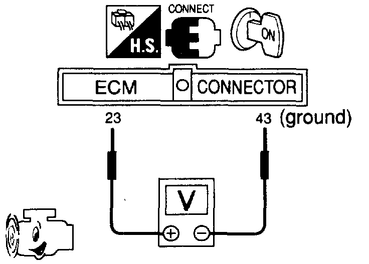
Pic 21
(4)Check the voltage between ECM terminal (23) and (43) (ground) and check the following:
- The voltage when accelerator pedal fully released is 0.3 - 0.7V.
- The voltage rise is linear in response to accelerator pedal depression.
- The voltage when accelerator pedal fully depressed is approximately 4V.
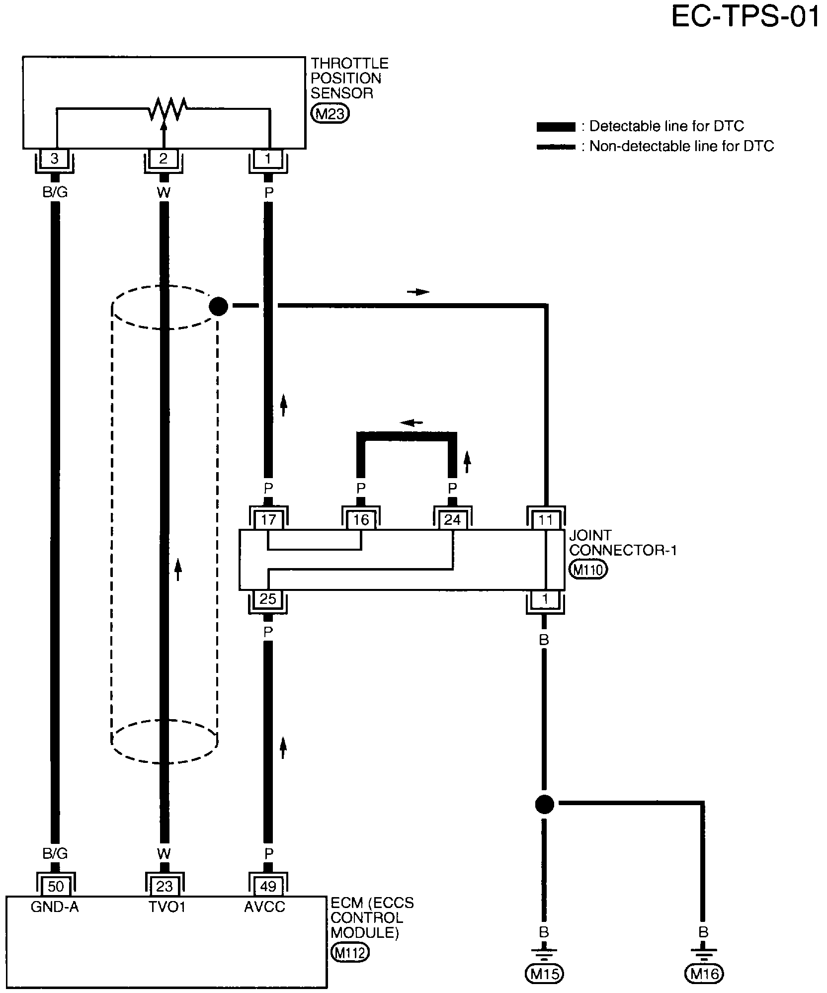
EC-TPS-01 Throttle Position (DTC P0120)
pic 22
WIRING DIAGRAM
pic 23
pic 24
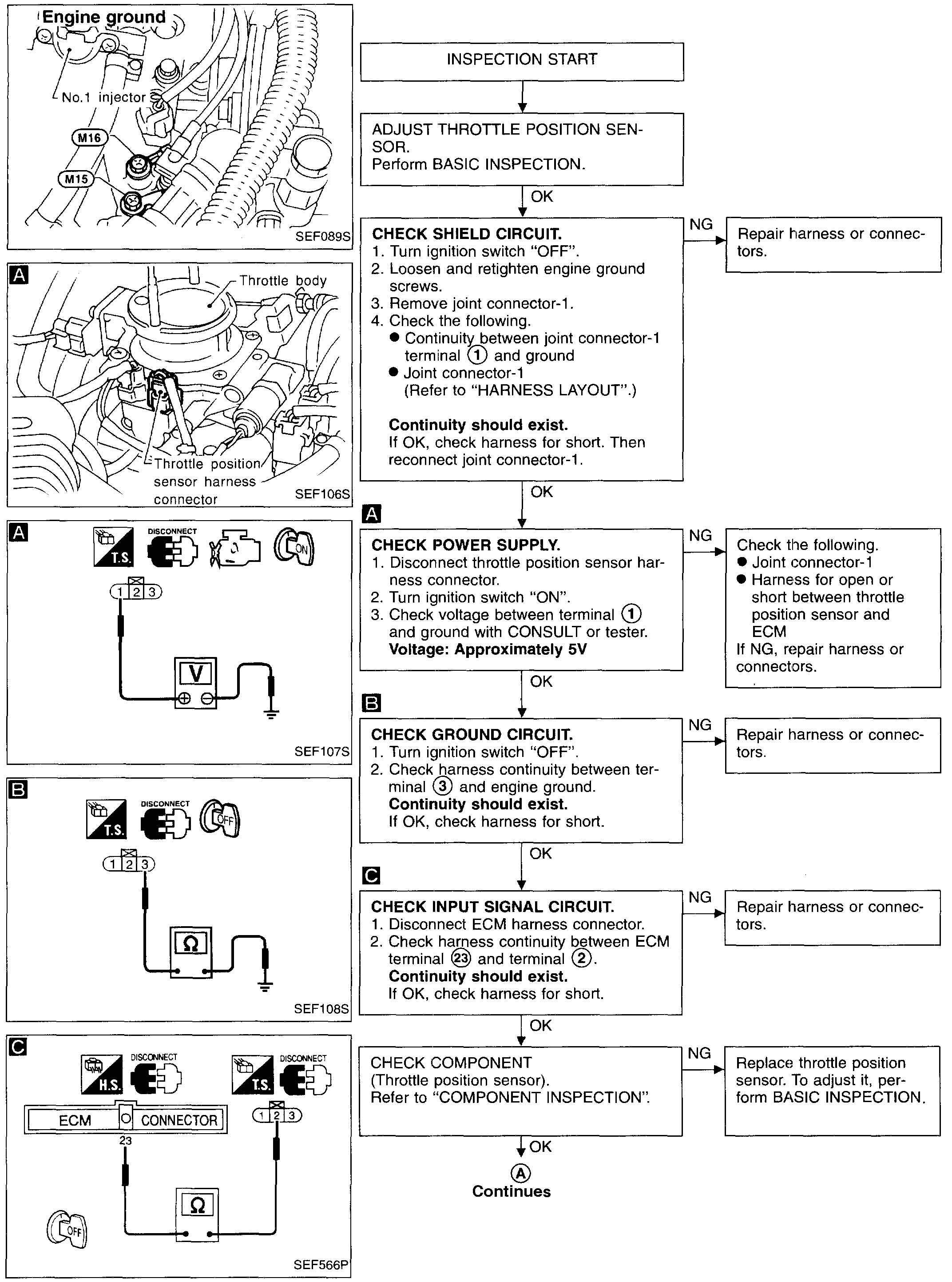
DIAGNOSTIC PROCEDURE
COMPONENT INSPECTION
Throttle Position Sensor
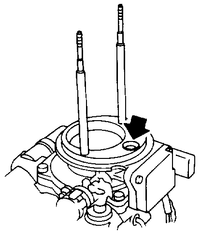
1. Start engine and warm it up sufficiently.
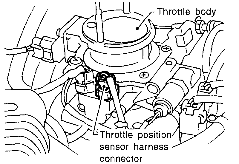
2. Turn ignition switch "OFF".
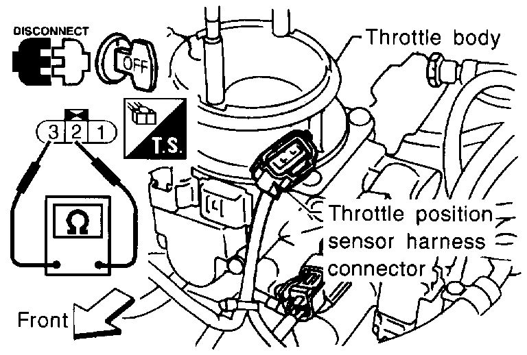
3. Disconnect throttle position sensor harness connector.
Pic 25
4. Check resistance between terminals 2 and 3 while opening throttle valve manually.
Throttle Valve conditions / Resistance at 25°C(77°F)
Completely closed / Approximately 0.5 k Ohms
Partially open / 0.5 - 0.4 K Ohms
Completely open / Approximately 4.0 K Ohms
If NG, replace throttle position sensor.
To adjust throttle position sensor, perform "BASIC INSPECTION".
____________________________
I hope something here helps.
Joe
Images (Click to make bigger)
Sunday, March 1st, 2020 AT 7:41 PM