Since it is happening after you drive it for awhile, it seems it could be heat related. A bad connection or a sensor could be the issue. Here is the entire list regarding the P0120. If you page through it, it explains how to test the sensor and connection with the ECM. The last test is for the throttle position sensor. I would suggest doing the test, but I would do it when everything is warm and you are experiencing the issue.
The attached pics correlate with the directions.
________________-
1997 Nissan-Datsun Truck D21 Hardbody XE 2WD L4-2389cc 2.4L SOHC MFI (KA24E)
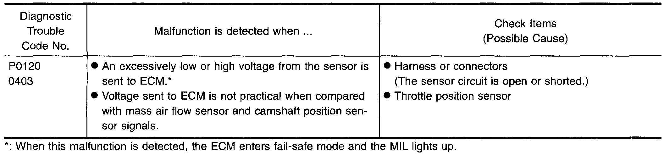
P0120
Vehicle ALL Diagnostic Trouble Codes ( DTC ) Testing and Inspection P Code Charts P0120
P0120
pic 1
pic 2
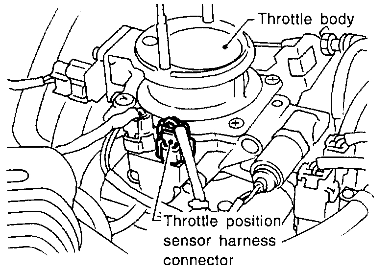
COMPONENT DESCRIPTION
The throttle position sensor responds to the accelerator pedal movement. This sensor is a kind of potentiometer which transforms the throttle position into output voltage and emits the voltage signal to the ECM. In addition, the sensor detects the opening and closing speed of the throttle valve and feeds the voltage signal to the ECM.
Idle position of the throttle valve is determined by the ECM receiving the signal from the throttle position sensor. This controls engine operation such as fuel cut. The throttle position sensor unit contains a built-in "Wide open and closed throttle position switch".
Pic 3
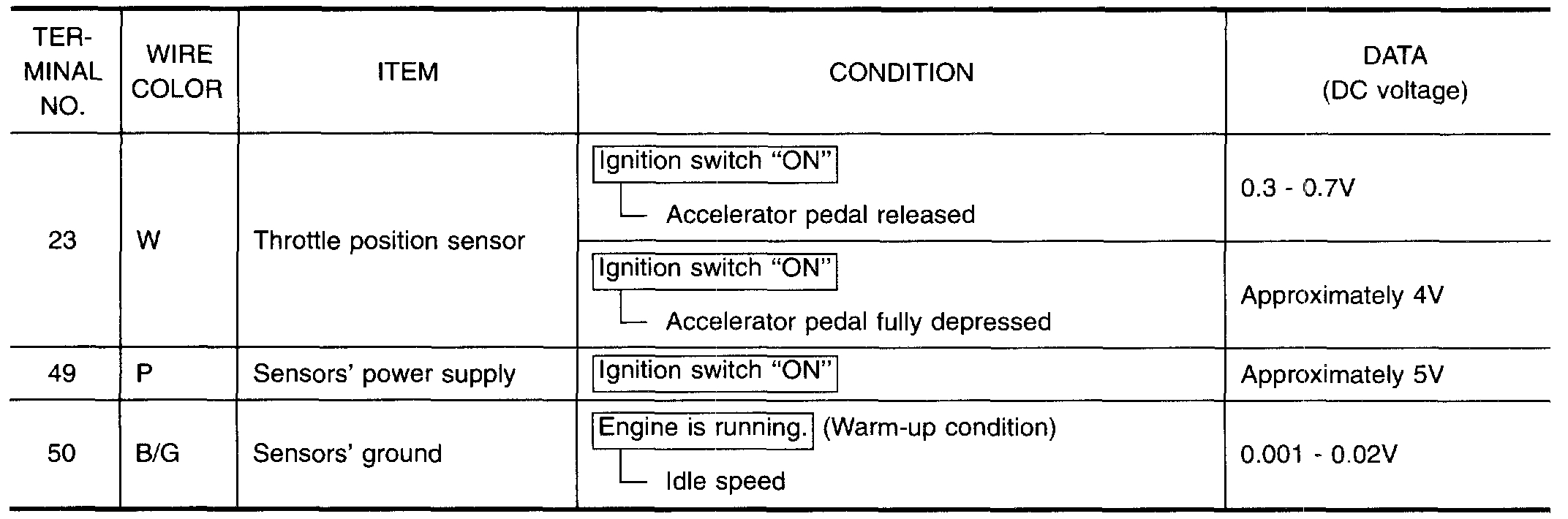
ECM TERMINALS AND REFERENCE VALUE
Specification data are reference values and are measured between each terminal and (43) (ECCS ground).
Pic 4
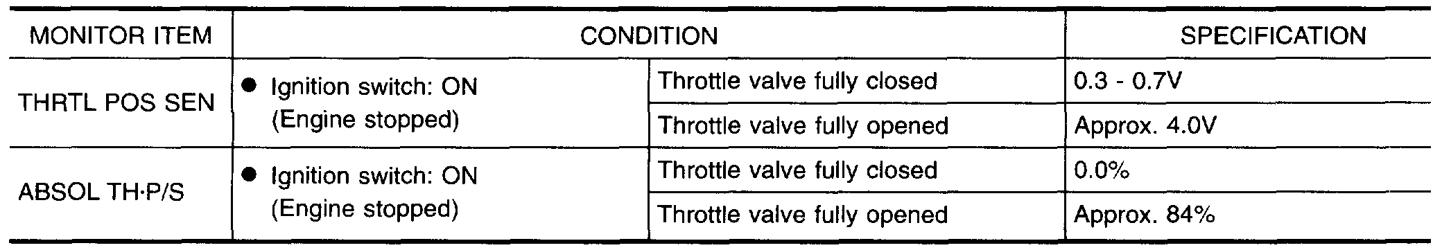
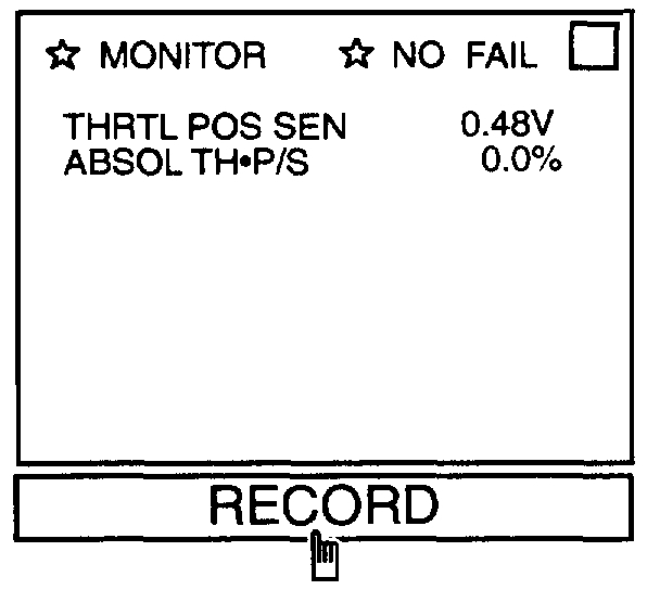
CONSULT REFERENCE VALUE IN DATA MONITOR MODE
Specification data are reference values
pic 5
ON BOARD DIAGNOSIS LOGIC
Engine operating condition in fail-safe mode
Throttle position will be determined based on the injected fuel amount and the engine speed.
Therefore, acceleration will be poor.
Condition / Driving Condition
When Engine is Idling / Normal
When accelerating / Poor accelerating
OVERALL FUNCTION CHECK
Use this procedure to check the overall function of the throttle position sensor circuit. During this check, a 1st trip DTC might not be confirmed.
With CONSULT
(1)Start engine and warm it up sufficiently.
(2)Turn ignition switch "OFF" and wait at least 7 seconds.
(3)Turn ignition switch "ON".
Pic 6
(4)Select "MANU TRIG" and "HI SPEED" in "DATA MONITOR" mode with CONSULT
(5)Select "THRTL POS SEN" and "AE3SOL TH.P/S" in "DATA MONITOR" mode with CONSULT.
(6)Press RECORD on CONSULT SCREEN at the same time accelerator pedal is depressed.
Pic 7
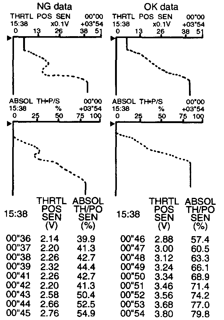
(7)Print out the recorded data and check the following:
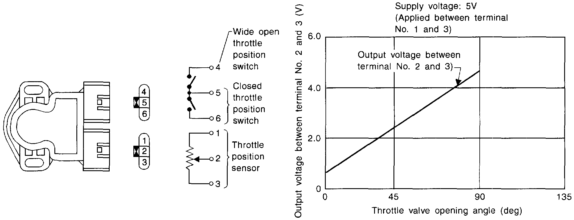
- The voltage when accelerator pedal fully released is 0.3 - 0.7V.
- The voltage rise is linear in response to accelerator pedal depression.
- The voltage when accelerator pedal fully depressed is approximately 4V.
OR
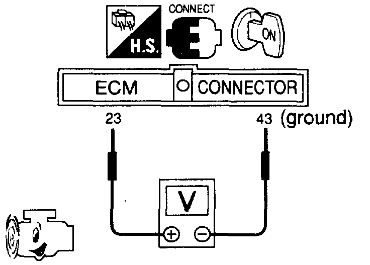
Without CONSULT
(1)Start engine and warm it up sufficiently.
(2)Turn ignition switch "OFF" and wait at least 7 seconds.
(3)Turn ignition switch "ON".
Pic 8
(4)Check the voltage between ECM terminal (23) and (43) (ground) and check the following:
- The voltage when accelerator pedal fully released is 0.3 - 0.7V.
- The voltage rise is linear in response to accelerator pedal depression.
- The voltage when accelerator pedal fully depressed is approximately 4V.
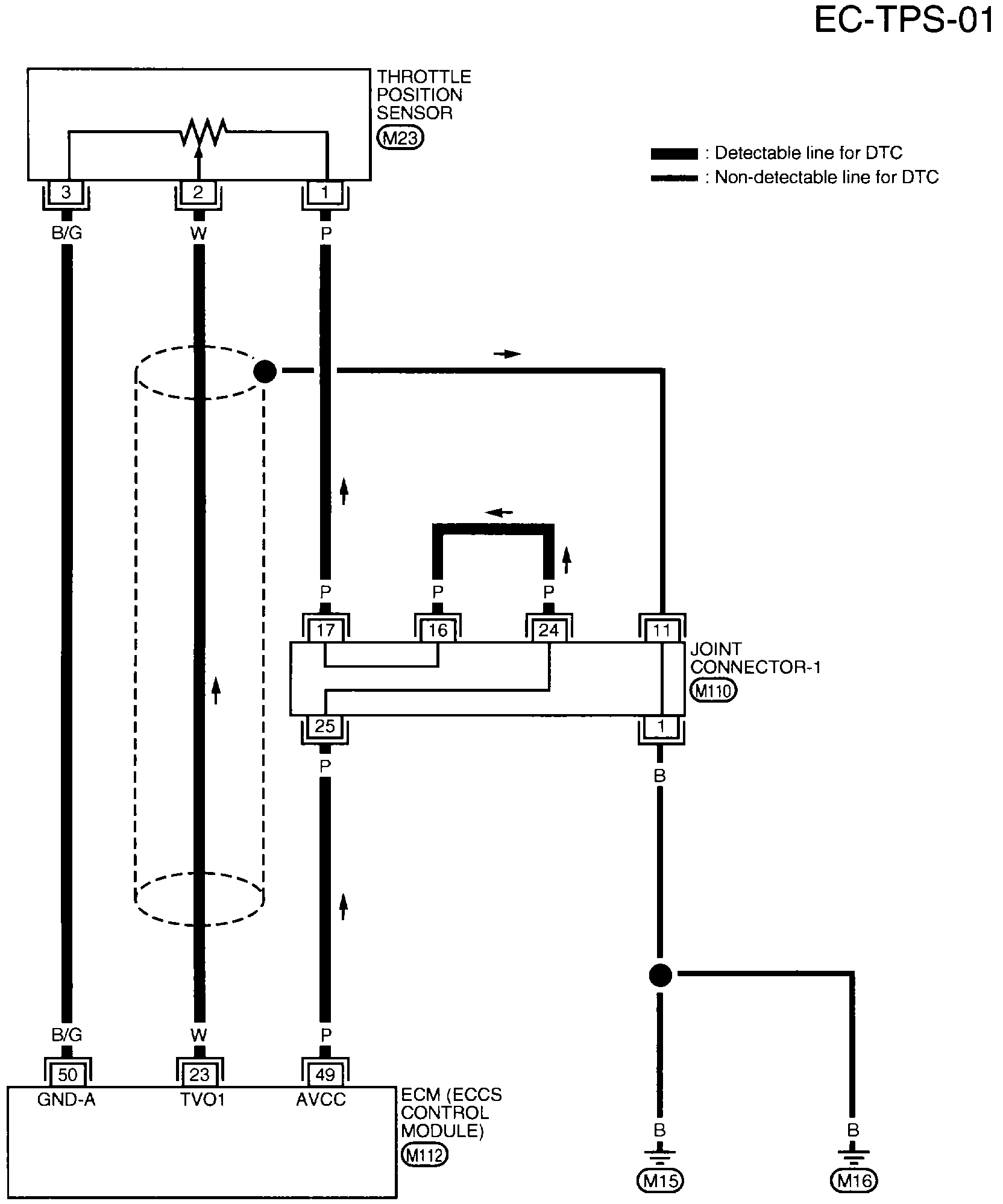
EC-TPS-01 Throttle Position (DTC P0120)
imageOpen In New TabZoom/Print
WIRING DIAGRAM
pic 9
pic 10
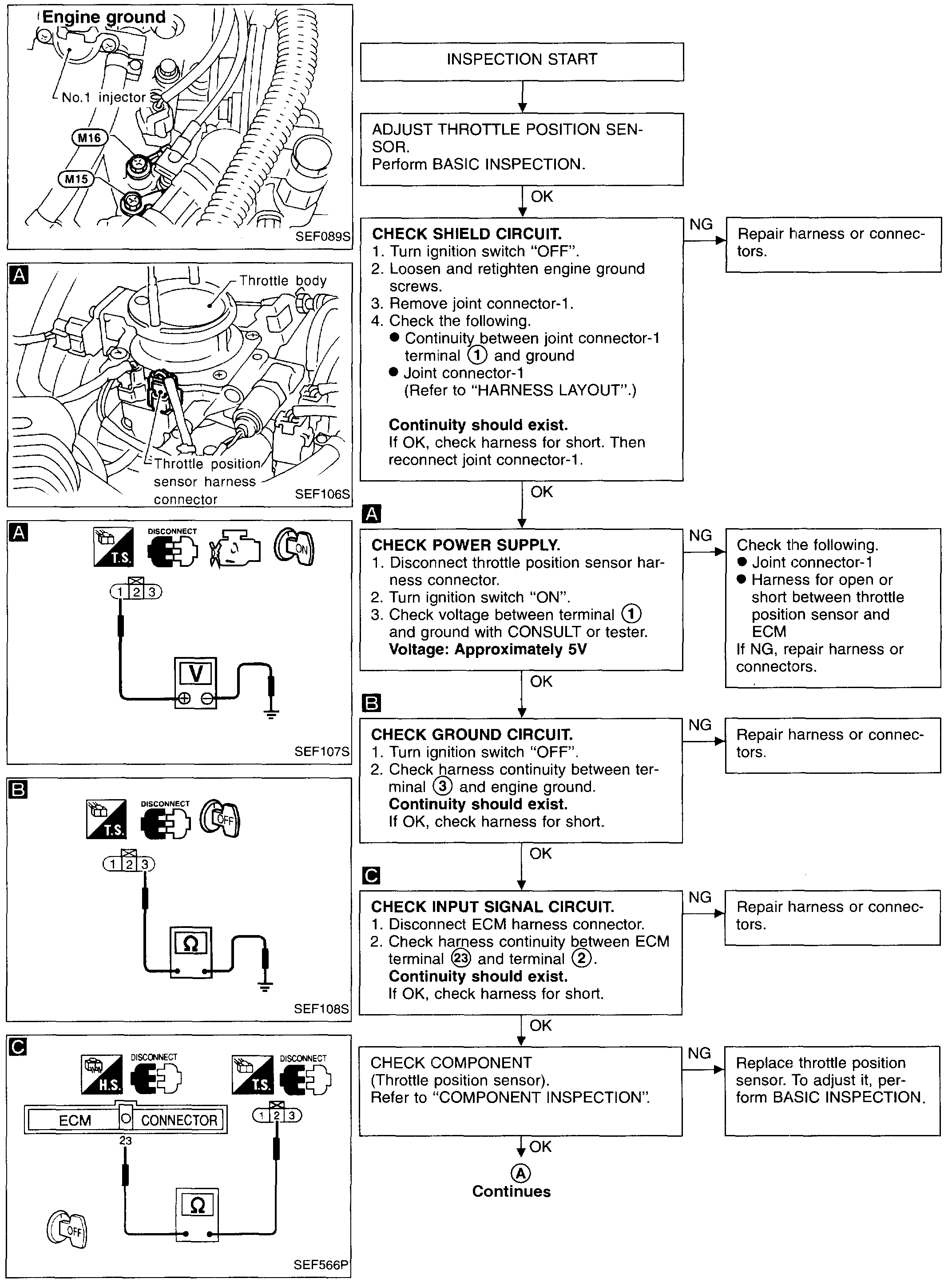
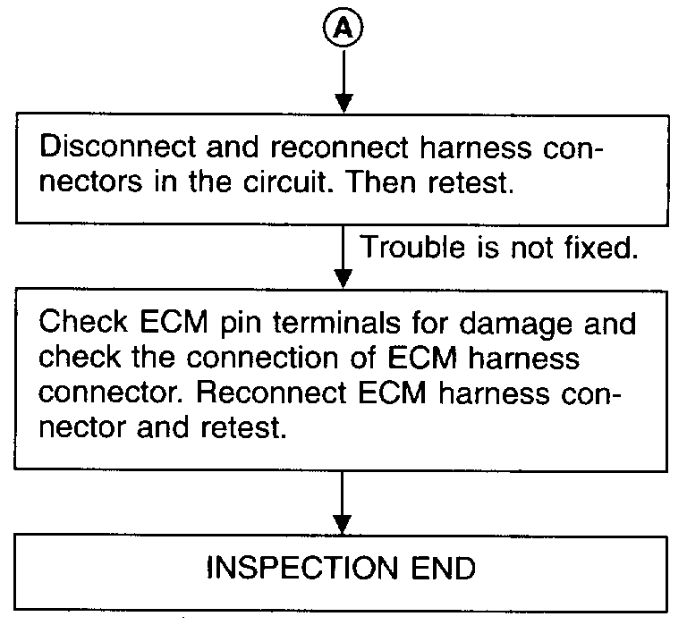
DIAGNOSTIC PROCEDURE
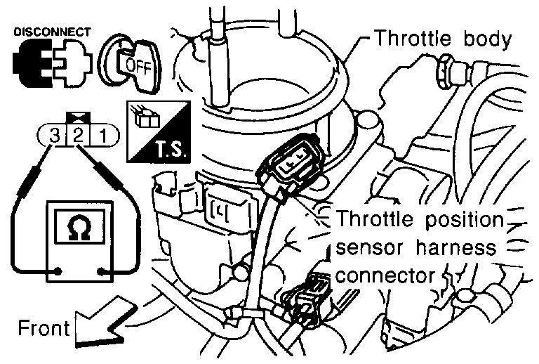
COMPONENT INSPECTION
Throttle Position Sensor
1. Start engine and warm it up sufficiently.
2. Turn ignition switch "OFF".
3. Disconnect throttle position sensor harness connector.
Pic 11
4. Check resistance between terminals 2 and 3 while opening throttle valve manually.
Throttle Valve conditions / Resistance at 25°C(77°F)
Completely closed / Approximately 0.5 k Ohms
Partially open / 0.5 - 0.4 K Ohms
Completely open / Approximately 4.0 K Ohms
If NG, replace throttle position sensor.
To adjust throttle position sensor, perform "BASIC INSPECTION".
____________________________
Let me know the results.
Joe
Images (Click to make bigger)
Sunday, February 23rd, 2020 AT 8:00 PM