2009 Pontiac G6 security light

Tiny
ZELLERDEREK4
  • MEMBER
  • 2009 PONTIAC G6
As I went to go plug in my scanner the car chime went off as if it was warming me of seatbelt not on the low fuel flashed on dic and light came on for less then 1 second and as that went off the security light came on and hasnt went off through a few key cycles now not sure how many but I tried to get it to go out with remote and restarting car now instead of having the codes u 2105 and u2107 it now has c0899 device 1 low voltage and u2105 emc communication does anyone have any clue of what "Device 1" would be
Wednesday, February 19th, 2014 AT 6:25 PM

8 Replies

Tiny
ZELLERDEREK4
  • MEMBER
  • 63 POSTS
I have also noticed that my evap monitoring system doesnt quite register but yet this code is coming up on my asb tab on my scanner page wen connected to computer would the evap come up under device 1? The fourms I have read all point back to Device 1
Was this
answer
helpful?
Yes
No
Wednesday, February 19th, 2014 AT 6:29 PM
Tiny
OBXAUTOMEDIC
  • MECHANIC
  • 3,711 POSTS
Hello,

Ok, from looking through it does not have anything stating device 1 but from what I read I would say that device 1 is the Battery since the code has to do with low voltage. Anyway below are a couple docs with the Code C0899. Hope this helps. If need more let me know.

DTC C0899 (PSCM)
Diagnostic Instructions (PSCM)
†Perform the prior to using this diagnostic procedure.
†Review for an overview of the diagnostic approach.
†provides an overview of each diagnostic category.
DTC Descriptor (PSCM)
DTC C0899 03
Device Voltage Low - PSCM
Diagnostic Fault Information (PSCM)
Circuit Short to Ground Open/High Resistance Short to Voltage Signal Performance
Battery Voltage C0899 03 C0899 03 - -
Ground - C0899 03 - -
Typical Scan Tool Data (PSCM)
Battery Voltage Signal - PSCM
Circuit Short to Ground Open Short to Voltage
Operating Conditions: Ignition ON, Engine OFF. Parameter Normal Value: 12.60 Volts
B+ 0.00 Volts 0.00 Volts 12.60 Volts
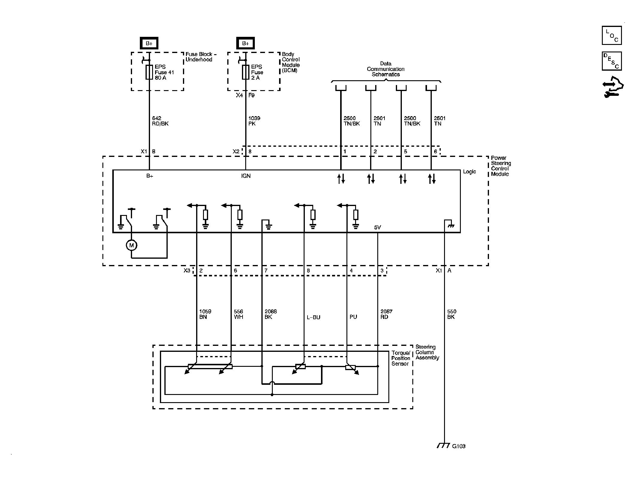
Circuit/System Description (PSCM)
The power steering control module (PSCM) monitors the battery voltage available in order to ensure the power steering system has adequate voltage levels to perform the system functions.
Conditions for Running the DTC (PSCM)
The ignition is ON.
Conditions for Setting the DTC (PSCM)
The power steering system voltage is less than 9 volts for 1 second.
Action Taken When the DTC Sets (PSCM)
†No steering assist is provided.
†The driver information center (DIC) displays the POWER STEERING message.
Conditions for Clearing the DTC (PSCM)
†The condition for the DTC is no longer present.
†The PSCM automatically clears the history DTC when a current DTC is not detected in 100 consecutive ignition cycles.
Diagnostic Aids (PSCM)
A low voltage DTC in multiple modules indicates a concern in the charging system.
Reference Information (PSCM)
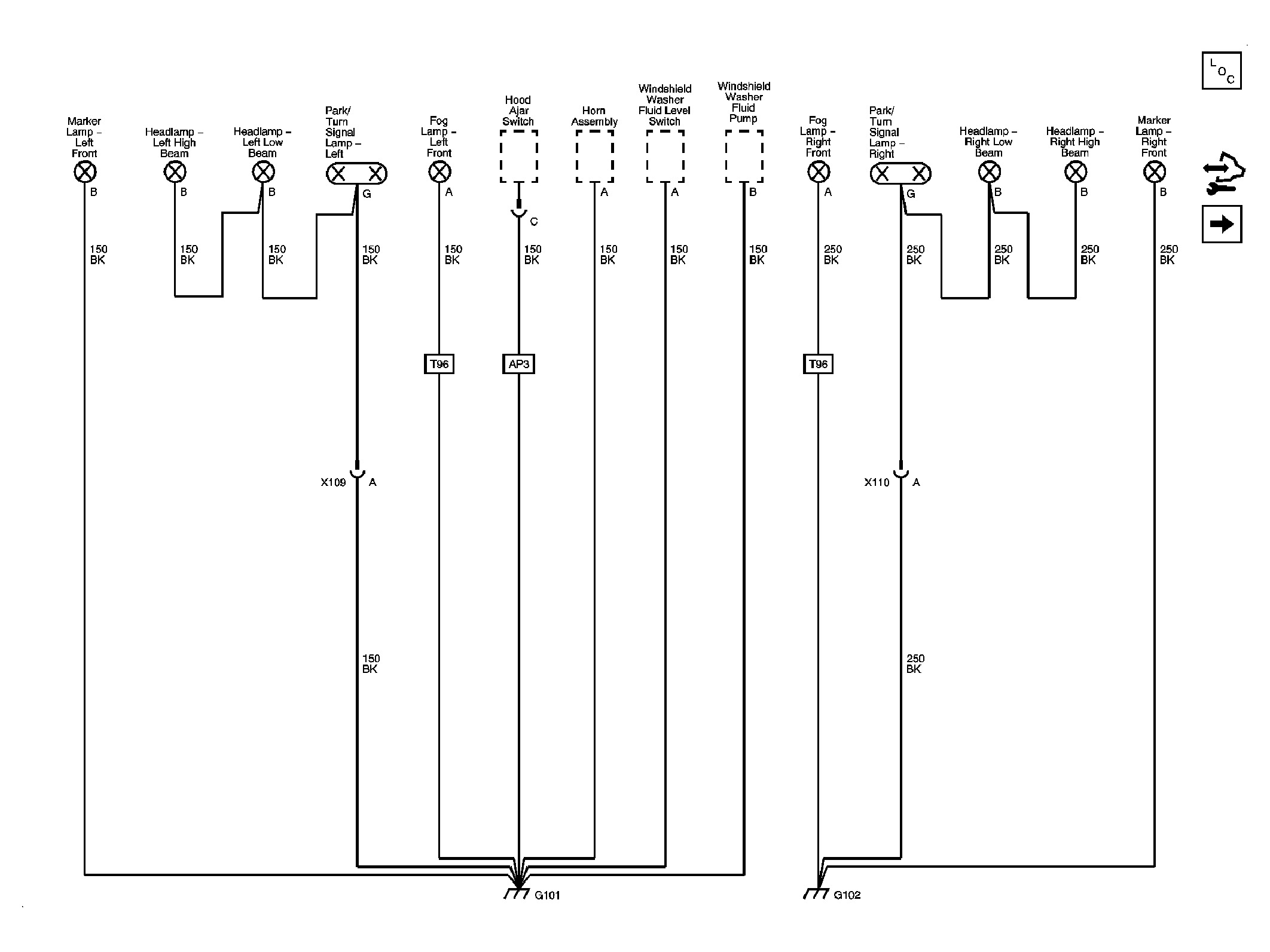
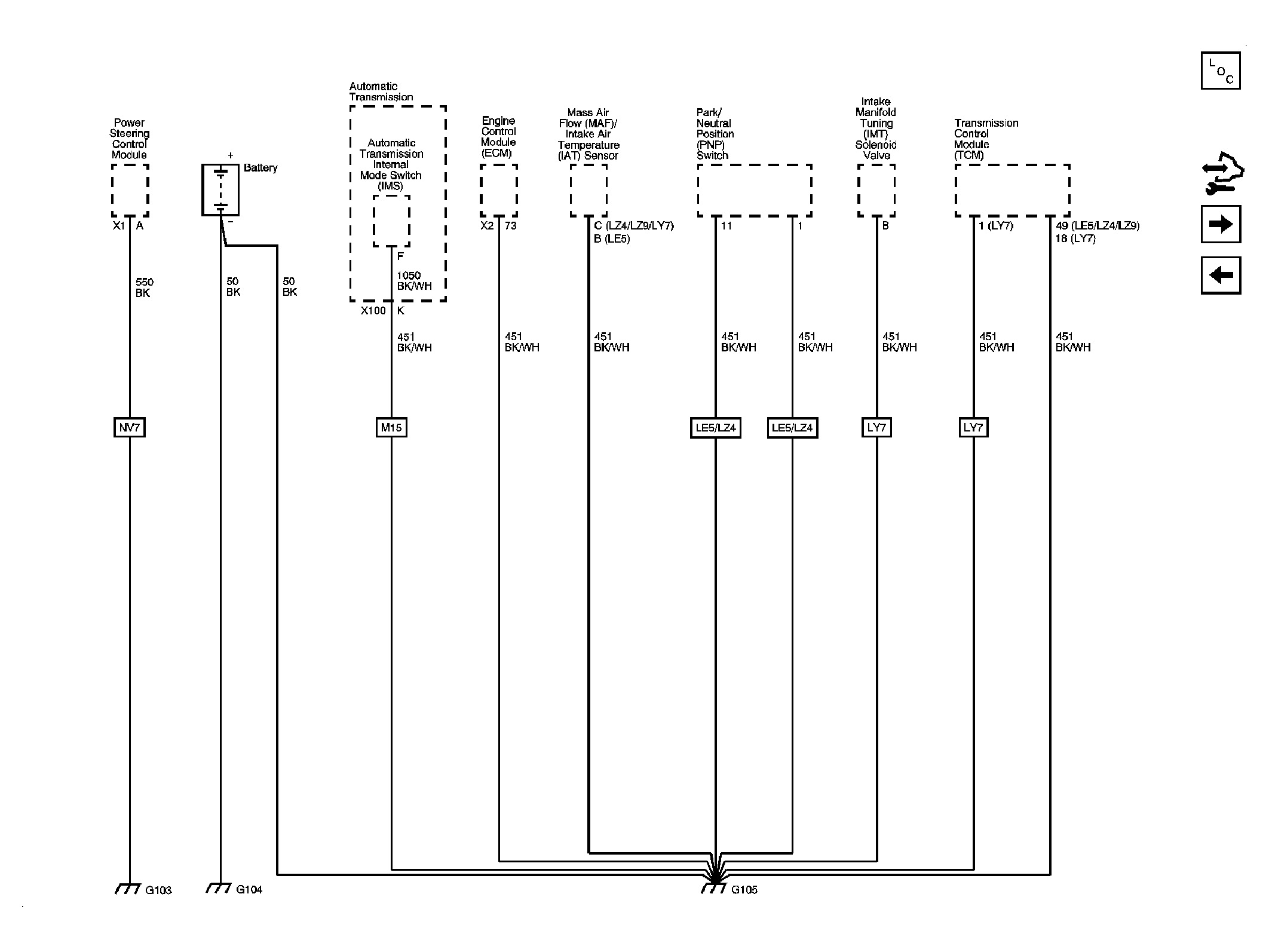
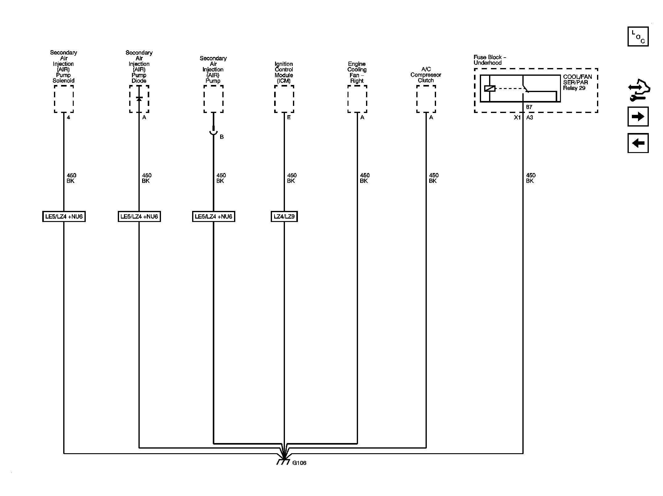
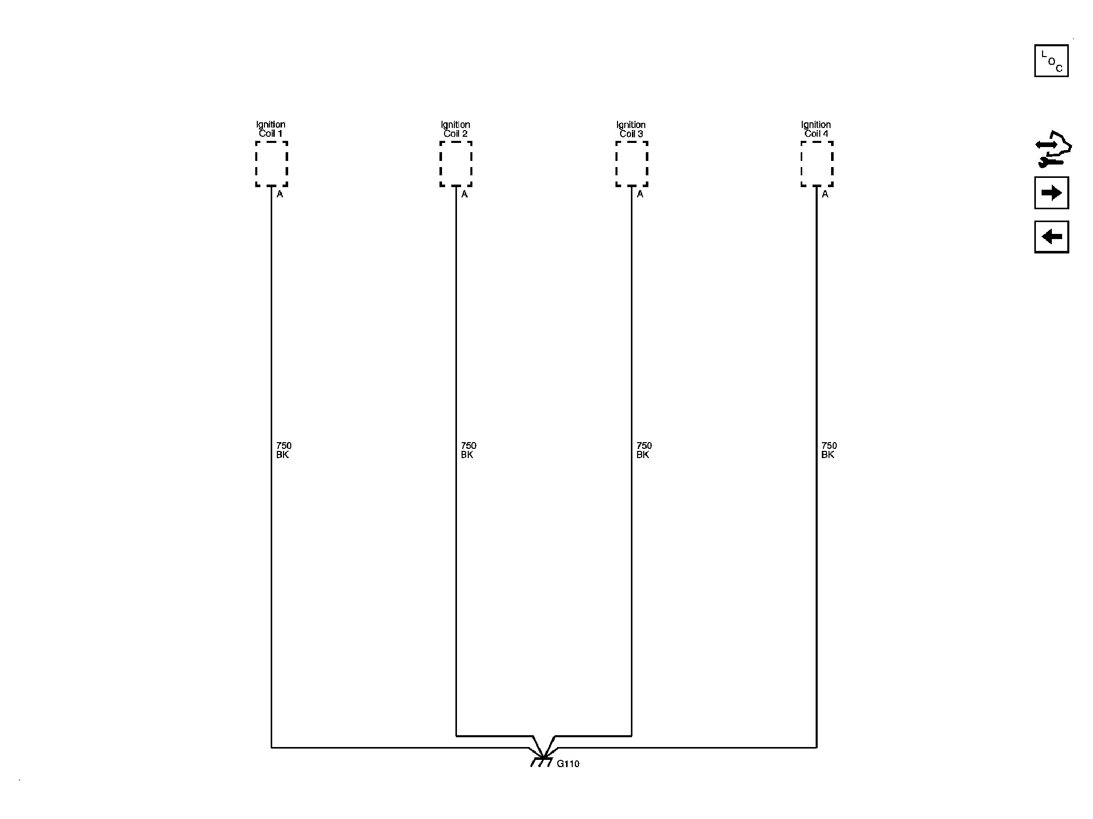
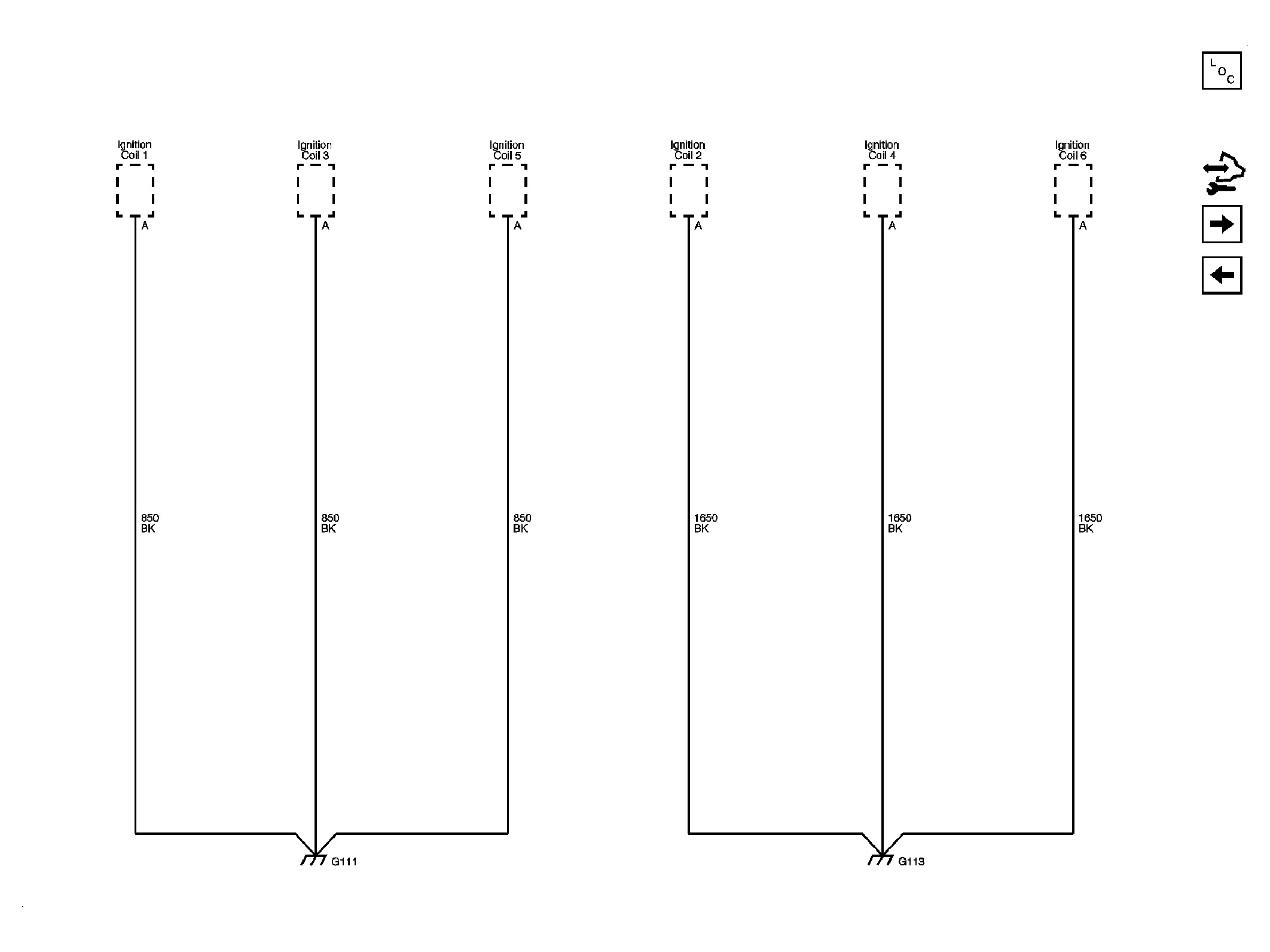
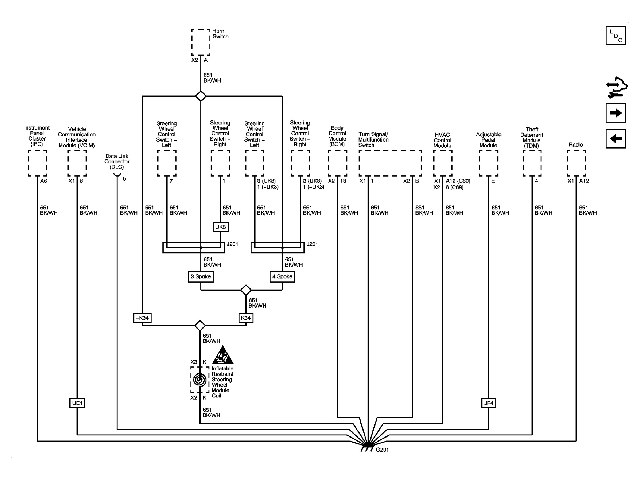
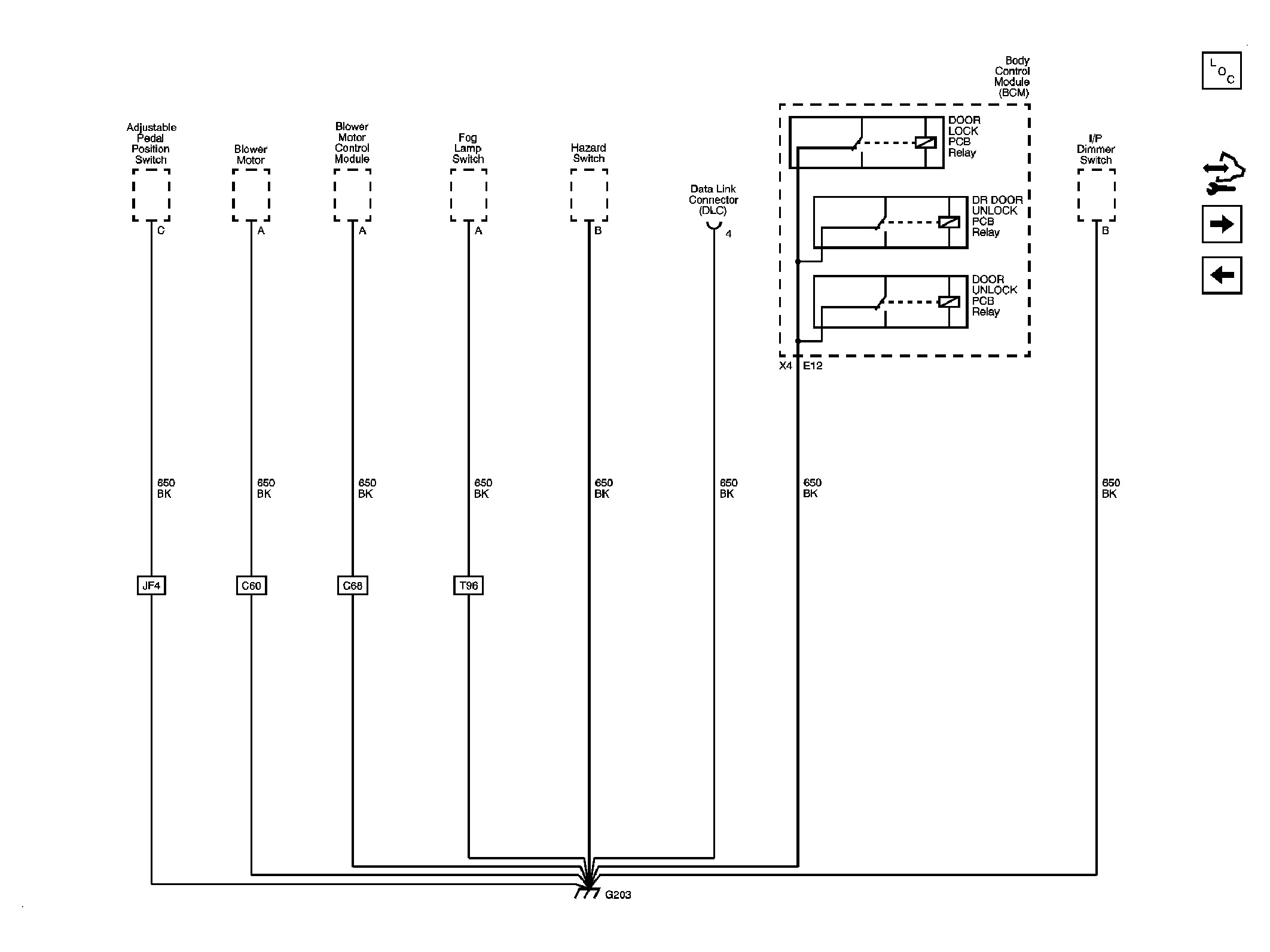
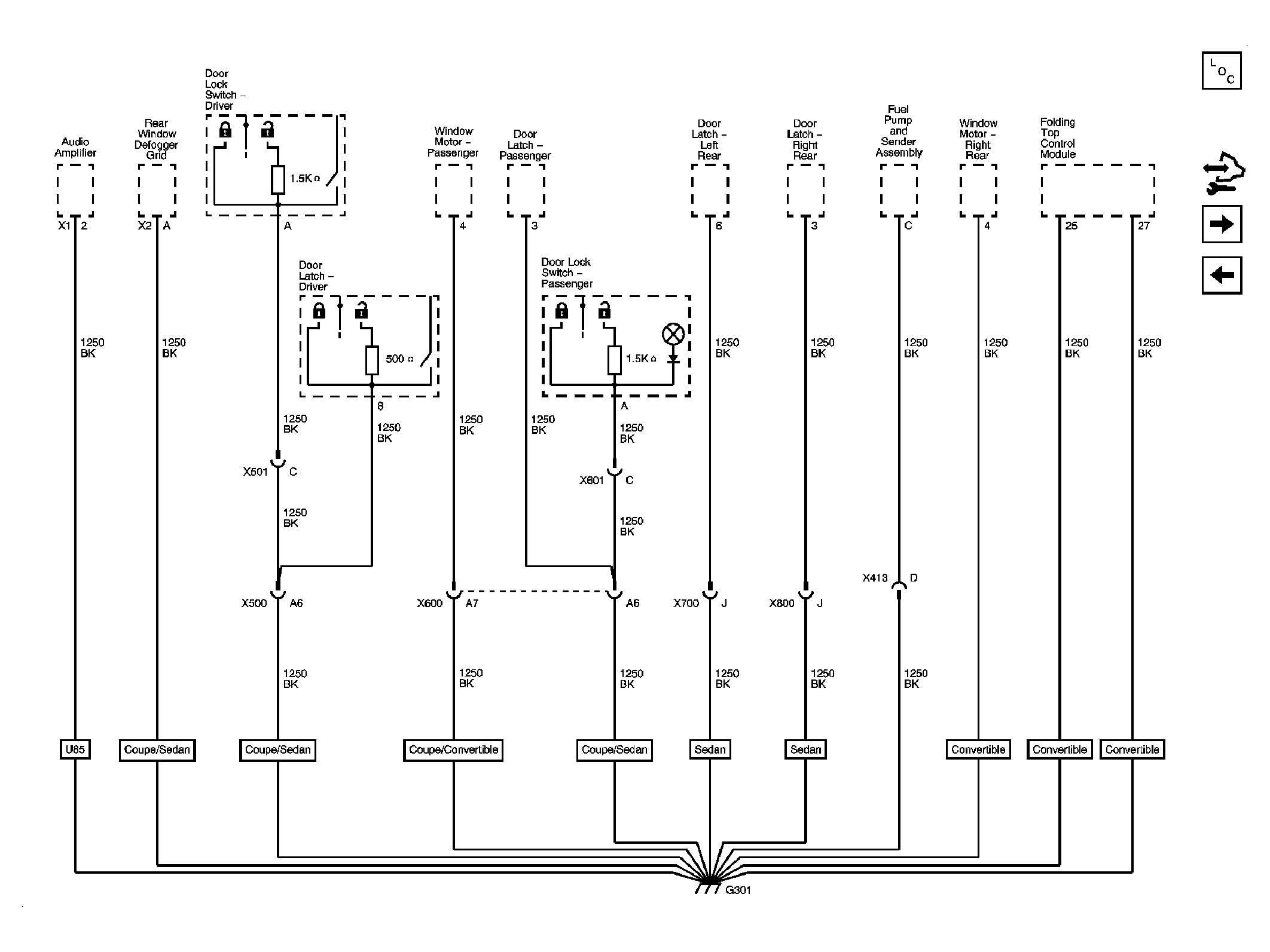
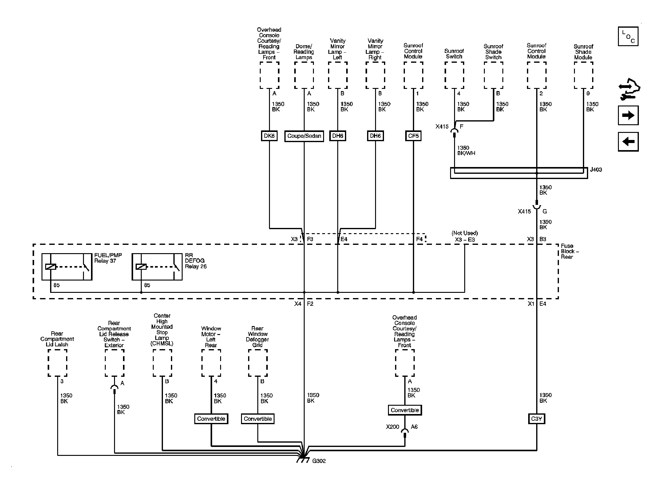
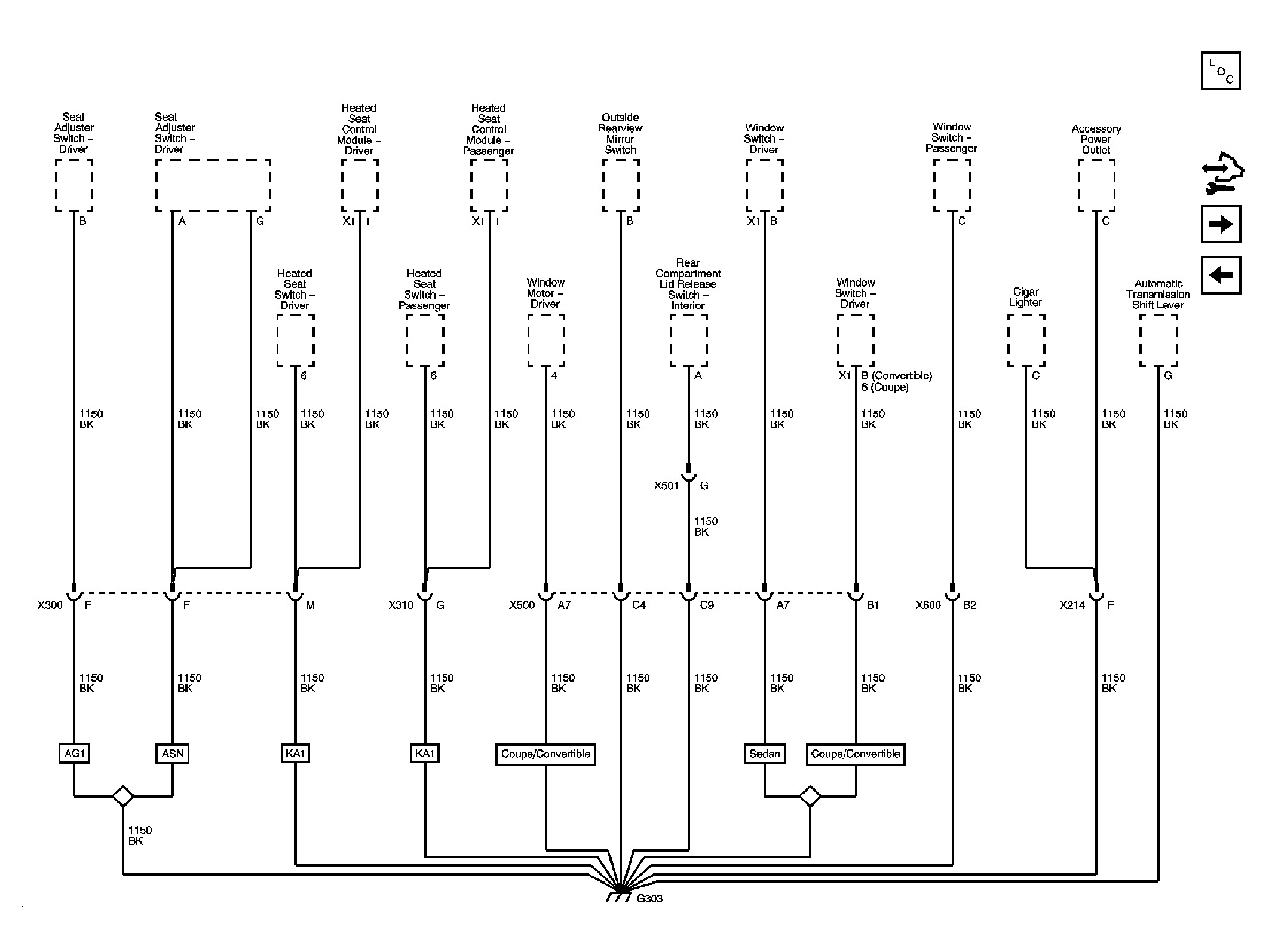
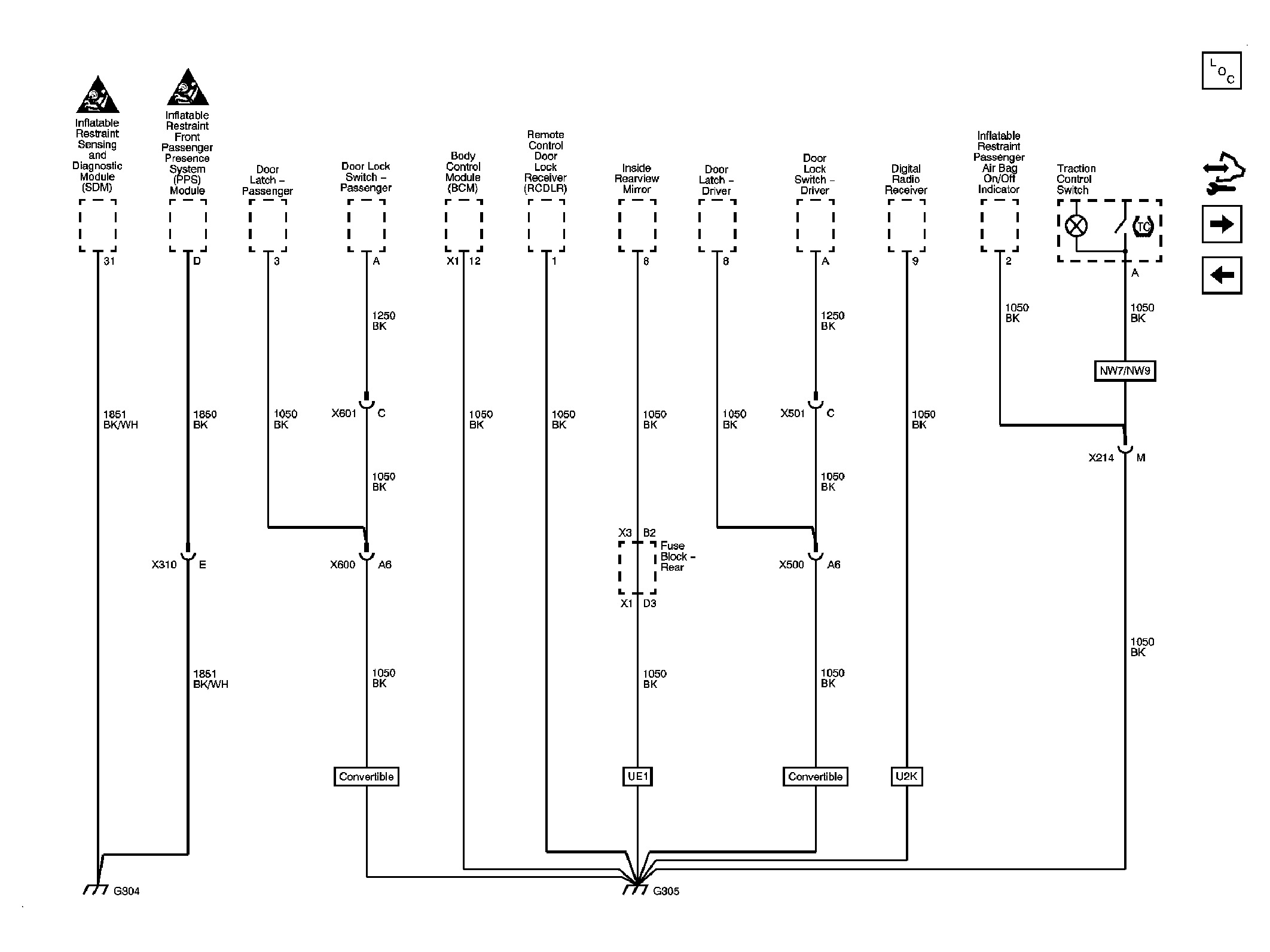
Schematic Reference
Connector End View Reference
Description and Operation
†or
â€
Electrical Information Reference
â€
â€
â€
â€
Scan Tool Reference
for scan tool information
Circuit/System Verification (PSCM)
1. Engine running, accessories OFF, measure and record the voltage at the battery voltage at the battery terminals. The voltage should be between 12.6 and 15.0 volts.
O If not within the specified range, refer to .
2. Observe the scan tool PSCM Battery Voltage Signal parameter. The reading should be between 12.6 and 15.0 volts.
Circuit/System Testing (PSCM)
1. Ignition OFF, disconnect the harness connector at the PSCM.
2. Ignition OFF and scan tool disconnected, open and close the drivers door, and wait 1 minute. Test for less than 5 ohms between the ground circuit terminal A X1 and ground.
O If greater than the specified range, test the ground circuit for an open/high resistance.
3. Verify that a test lamp illuminates between the B+ circuit terminal B X1 and ground.
O If the test lamp does not illuminate, test the B+ circuit for a short to ground or an open/high resistance.
4. Ignition ON, verify that a test lamp illuminates between the ignition circuit terminal 8 X2 and ground.
O If the test lamp does not illuminate, test the ignition circuit for a short to ground or an open/high resistance.
5. If all circuits test normal, replace the PSCM.
Repair Procedures (PSCM)
Perform the after completing the diagnostic procedure.
For PSCM replacement, setup and programming.

DTC C0899 (EBCM)
Diagnostic Instructions (EBCM)
†Perform the prior to using this diagnostic procedure.
†Review for an overview of this diagnostic approach.
†provides an overview of each diagnostic category.
DTC Descriptor (EBCM)
DTC C0899 00
Device Voltage Low
Diagnostic Fault Information (EBCM)
Circuit Short to Ground Open/High Resistance Short to Voltage Signal Performance
B+ C0899 00 C0899 00 - -
Ground - C0899 00 - -
Typical Scan Tool Data (EBCM)
Battery Voltage Signal - EBCM
Circuit Short to Ground Open Short to Voltage
Operating Conditions: Ignition ON, engine OFF. Parameter Normal Value: 12.60 Volts
B+ 0.00 Volts 0.00 Volts 12.60 Volts
Circuit/System Description (EBCM)
The electronic brake control module (EBCM) monitors the ignition voltage level available for system operation. A low voltage condition prevents the system from operating properly. If the EBCM detects low system voltage, DTC C0899 00 sets.
Conditions for Running the DTC (EBCM)
The ignition is ON.
Conditions for Setting the DTC (EBCM)
The EBCM detects that the system voltage is less than 9 volts.
Action Taken When the DTC Sets (EBCM)
†The antilock brake system (ABS) and dynamic rear proportioning (DRP), hydraulic brake assist (HBA), and traction control system (TCS) are disabled.
†The vehicle stability enhancement system (VSES) is disabled, if equipped.
†The ABS, BRAKE, and TRACTION CONTROL OFF indicators turn ON.
†The STABILITY SYSTEM OFF indicator turns ON, if equipped.
†The radio displays the SERVICE TRACTION message.
†The radio displays the ESC OFF and SERVICE ESC messages, if equipped.
Conditions for Clearing the DTC (EBCM)
†The DTC will pass when the EBCM detects that the system voltage is greater than 9.5 volts for 100 msec.
†The EBCM automatically clears a history DTC when a current DTC is not detected in 100 consecutive drive cycles.
†The indicators and radio messages turn OFF when the DTC passes.
Diagnostic Aids (EBCM)
A low voltage DTC in multiple modules indicates a concern in the charging system.
Reference Information (EBCM)
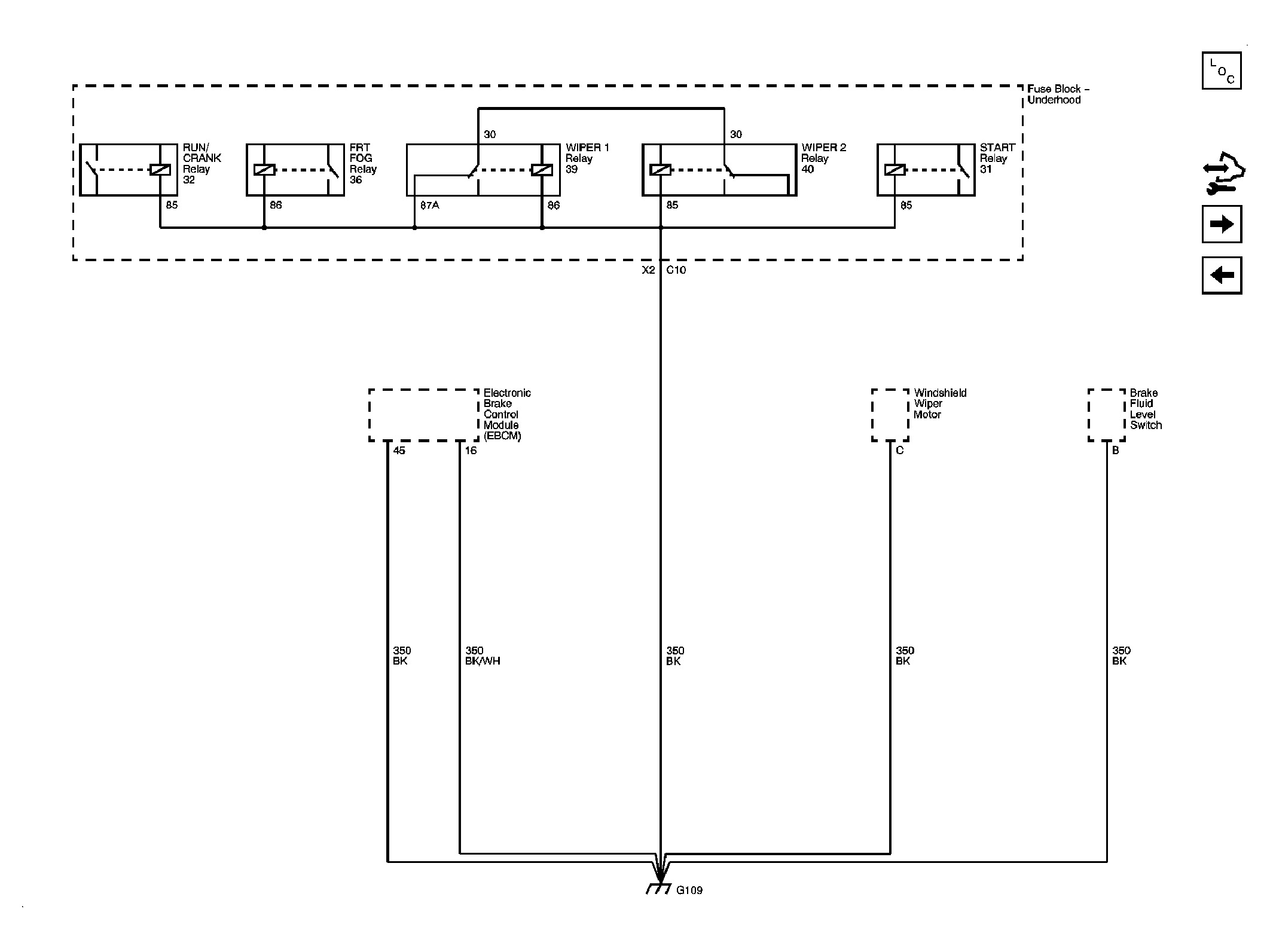
Schematic Reference
Connector End View Reference
Description and Operation
â€
â€
Electrical Information Reference
â€
â€
â€
â€
Scan Tool Reference
for scan tool information
Circuit/System Verification (EBCM)
1. Engine running, accessories OFF, measure and record the voltage at the battery voltage at the battery terminals. The voltage should be between 12.6 and 15.0 volts.
O If not within the specified range, refer to .
2. Observe the scan tool EBCM Battery Voltage Signal parameter. The reading should be between 12.60 and 15.00 volts.
Circuit/System Testing (EBCM)
1. Ignition OFF, disconnect the harness connector at the EBCM.
2. Ignition OFF and scan tool disconnected, open and close the driver door, and wait 1 minute. Test for less than 5 ohms between the ground circuit terminals listed below and ground.
O Terminal 13
o Terminal 38
o If greater than the specified range, test the ground circuit for an open/high resistance.
3. Verify that a test lamp illuminates between the B+ circuit terminal 1 and ground.
O If the test lamp does not illuminate, test the B+ circuit for a short to ground or an open/high resistance.
4. Ignition ON, verify that a test lamp illuminates between the ignition circuit terminal 25 and ground.
O If the test lamp does not illuminate, test the ignition circuit for a short to ground or an open/high resistance.
5. If all circuits test normal, replace the EBCM.
Repair Procedures (EBCM)
Perform the after completing the diagnostic procedure.
For EBCM replacement, setup, and programming.
Was this
answer
helpful?
Yes
No
Wednesday, February 19th, 2014 AT 7:36 PM
Tiny
ZELLERDEREK4
  • MEMBER
  • 63 POSTS
I have had problems with my eps a few times in the past replaced a ground cable and it got better do you think this could be related to an intermittant problem with the tourque/position sensor? Or module/ motor
Was this
answer
helpful?
Yes
No
Thursday, February 20th, 2014 AT 5:29 AM
Tiny
OBXAUTOMEDIC
  • MECHANIC
  • 3,711 POSTS
Ok, lets look at the u2105 and u2107 Codes

DTC U2105 00 - Lost Communication With Engine Control System

DTC U2107 00 - Lost Communication With Body Control System

With that I would look into the wiring for shorts bad connection etc.

Attached are Ground Distribution Schematics

Testing for Intermittent Conditions and Poor Connections

Special Tools

J 35616 GM-Approved Terminal Test Kit
J-38125 Terminal Repair Kit. See.

Testing

When the condition is not currently present, but is indicated in DTC history, the cause may be intermittent. An intermittent may also be the cause when there is a customer complaint, but the symptom cannot be duplicated. Refer to the Symptom Table of the system that is suspect of causing the condition before trying to locate an intermittent condition.

Most intermittent conditions are caused by faulty electrical connections or wiring. Inspect for the following items:

Wiring broken inside the insulation
Poor connection between the male and female terminal at a connector
Poor terminal to wire connection-Some conditions which fall under this description are poor crimps, poor solder joints, crimping over the wire insulation rather than the wire itself, and corrosion in the wire to terminal contact area, etc.
Pierced or damaged insulation can allow moisture to enter the wiring causing corrosion. The conductor can corrode inside the insulation, with little visible evidence. Look for swollen and stiff sections of wire in the suspect circuits.
Wiring which has been pinched, cut, or its insulation rubbed through may cause an intermittent open or short as the bare area touches other wiring or parts of the vehicle.
Wiring that comes in contact with hot or exhaust components
Refer to in order to duplicate the conditions required, in order to verify the customer concern.
Refer to for test procedures to detect intermittent open, high resistance, short to ground, and short to voltage conditions.
Refer to for advanced intermittent diagnosis and Vehicle Data Recorder operation.

Testing for Proper Terminal Contact

It is important to test terminal contact at the component and any inline connectors before replacing a suspect component. Mating terminals must be inspected to ensure good terminal contact. A poor connection between the male and female terminal at a connector may be the result of contamination or deformation.

Contamination may be caused by the connector halves being improperly connected. A missing or damaged connector seal, damage to the connector itself, or exposing the terminals to moisture and dirt can also cause contamination. Contamination, usually in the underhood or underbody connectors, leads to terminal corrosion, causing an open circuit or intermittently open circuit.

Deformation is caused by probing the mating side of a connector terminal without the proper adapter. Always use the J 35616 when probing connectors. Other causes of terminal deformation are improperly joining the connector halves, or repeatedly separating and joining the connector halves. Deformation, usually to the female terminal contact tang, can result in poor terminal contact causing an open or intermittently open circuit.
Testing for Proper Terminal Contact in Bussed Electrical Centers (BEC)

It is very important to use the correct test adapter when testing for proper terminal contact of fuses and relays in a bussed electrical center (BEC). Use J-35616-35 to test for proper terminal contact. Failure to use J-35616-35 can result in improper diagnosis of the BEC.

Follow the procedure below in order to test terminal contact:

Separate the connector halves.
Visually inspect the connector halves for contamination. Contamination may result in a white or green build-up within the connector body or between terminals. This causes high terminal resistance, intermittent contact, or an open circuit. An underhood or underbody connector that shows signs of contamination should be replaced in its entirety: terminals, seals, and connector body.
Using an equivalent male terminal from the J-38125 , test that the retention force is significantly different between a good terminal and a suspect terminal. See. Replace the female terminal in question.

Flat Wire (Dock and Lock) Connectors

There are no serviceable parts for flat wire (dock and lock) connectors on the harness side or the component side.

Follow the procedure below in order to test terminal contact:

Remove the component in question.
Visually inspect each side of the connector for signs of contamination. Avoid touching either side of the connector as oil from your skin may be a source of contamination as well.
Visually inspect the terminal bearing surfaces of the flat wire circuits for splits, cracks, or other imperfections that could cause poor terminal contact. Visually inspect the component side connector to ensure that all of the terminals are uniform and free of damage or deformation.
Insert the appropriate adapter from the on the flat wire harness connector in order to test the circuit in question.

Control Module/Component Voltage and Grounds

Poor voltage or ground connections can cause widely varying symptoms.

Test all control module voltage supply circuits. Many vehicles have multiple circuits supplying voltage to a control module. Other components in the system may have separate voltage supply circuits that may also need to be tested. Inspect connections at the module/component connectors, fuses, and any intermediate connections between the voltage source and the module/component. A test lamp or a DMM may indicate that voltage is present, but neither tests the ability of the circuit to carry sufficient current. Ensure that the circuit can carry the current necessary to operate the component. Refer to and.
Test all control module ground and system ground circuits. The control module may have multiple ground circuits. Other components in the system may have separate grounds that may also need to be tested. Inspect grounds for clean and tight connections at the grounding point. Inspect the connections at the component and in splice packs, where applicable. Ensure that the circuit can carry the current necessary to operate the component. Refer to and.

Temperature Sensitivity

An intermittent condition may occur when a component/connection reaches normal operating temperature. The condition may occur only when the component/connection is cold, or only when the component/connection is hot.
Freeze Frame, Failure Records, Snapshot, or Vehicle Data Recorder data may help with this type of intermittent condition, where applicable.
If the intermittent is related to heat, review the data for a relationship with the following:
High ambient temperatures
Underhood/engine generated heat
Circuit generated heat due to a poor connection, or high electrical load
Higher than normal load conditions, towing, etc.
If the intermittent is related to cold, review the data for the following:
Low ambient temperatures-In extremely low temperatures, ice may form in a connection or component. Inspect for water intrusion.
The condition only occurs on a cold start.
The condition goes away when the vehicle warms up.
Information from the customer may help to determine if the trouble follows a pattern that is temperature related.
If temperature is suspected of causing an intermittent fault condition, attempt to duplicate the condition. Refer to in order to duplicate the conditions required.

Electromagnetic Interference (EMI) and Electrical Noise

Some electrical components/circuits are sensitive to electromagnetic interference (EMI) or other types of electrical noise. Inspect for the following conditions:

A misrouted harness that is too close to high voltage/high current devices such as secondary ignition components, motors, generator etc-These components may induce electrical noise on a circuit that could interfere with normal circuit operation.
Electrical system interference caused by a malfunctioning relay, or a control module driven solenoid or switch-These conditions can cause a sharp electrical surge. Normally, the condition will occur when the malfunctioning component is operating.
Improper installation of non-factory or aftermarket add on accessories such as lights, 2-way radios, amplifiers, electric motors, remote starters, alarm systems, cell phones, etc-These accessories may lead to interference while in use, but do not fail when the accessories are not in use. Refer to .
Test for an open diode across the A/C compressor clutch and for other open diodes. Some relays may contain a clamping diode.
The generator may be allowing AC noise into the electrical system.

Incorrect Control Module

There are only a few situations where reprogramming a control module is appropriate:
A new service control module is installed.
A control module from another vehicle is installed.
Revised software/calibration files have been released for this vehicle.
NOTE: DO NOT re-program the control module with the SAME software/calibration files that are already present in the control module. This is not an effective repair for any type of concern.
Verify that the control module contains the correct software/calibration. If incorrect programming is found, reprogram the control module with the most current software/calibration. Refer to for replacement, setup, and programming.
Was this
answer
helpful?
Yes
No
Thursday, February 20th, 2014 AT 6:50 PM
Tiny
ZELLERDEREK4
  • MEMBER
  • 63 POSTS
Alright I will look over and study these now that my security light went out my airbag light is on and says svc airbag on dic I have gone over pretty my 90% of ground connections I believe but am going to check again bc I determind to find the cause I'm hoping that the symptoms that I am listing through out all my posts will point me in the right direction from a tech who has experienced this problem or similar to this
Was this
answer
helpful?
Yes
No
Thursday, February 20th, 2014 AT 7:02 PM
Tiny
OBXAUTOMEDIC
  • MECHANIC
  • 3,711 POSTS
Ok, I just remembered something.

Do you have Tilt Steering? If so check wiring in steering column at the tilt area. The vehicle I had of course it was a few years ago that is were I finally found the problem.
Was this
answer
helpful?
Yes
No
Friday, February 21st, 2014 AT 4:32 PM
Tiny
ZELLERDEREK4
  • MEMBER
  • 63 POSTS
Yea it does was the problem related to the torque sensor at all? I have a 2009 g6 hasn't happened for a while but power steering used to cut out on me from time to time and I don't ever hardly move my steering position it's also telescoping
Was this
answer
helpful?
Yes
No
Friday, February 21st, 2014 AT 4:52 PM
Tiny
OBXAUTOMEDIC
  • MECHANIC
  • 3,711 POSTS
No, after hours of searching finally found some wire that were broke inside the sheath at the knuckle where steering wheel pivots. Attached it the Schematic for the Power Steering
Was this
answer
helpful?
Yes
No
Saturday, February 22nd, 2014 AT 3:12 PM

Please login or register to post a reply.

Sponsored links