TROUBLE SHOOTING
Check battery for state of charge. Check cable connections at battery and starter motor. Ensure
transmission is fully engaged in Park or Neutral, or clutch pedal is fully depressed. Check fuse No. 3
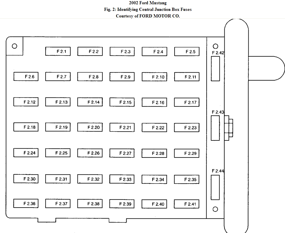
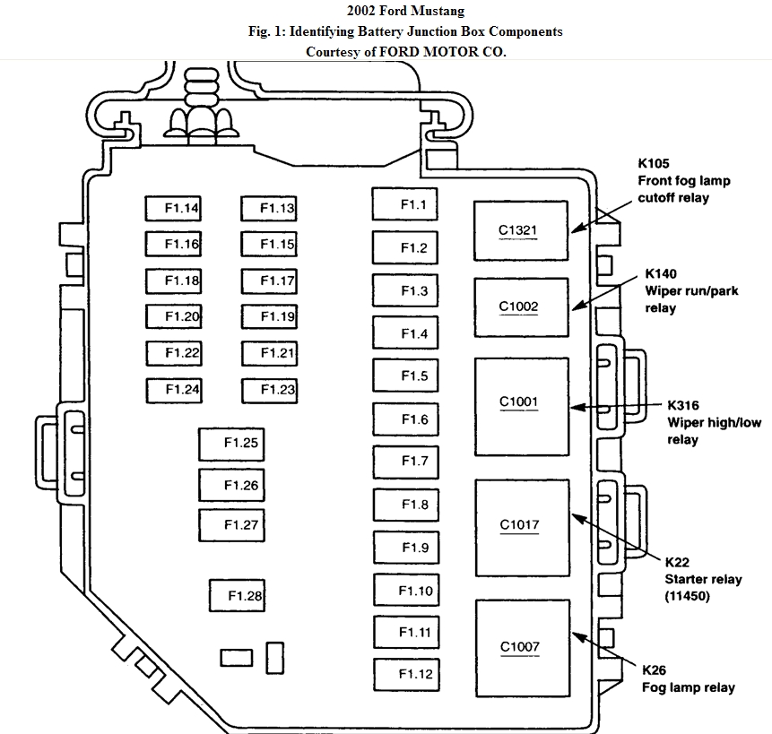
(40-amp) in battery junction box. See Fig. 1. Check fuse No. 6 (20-amp) in central junction box. See
Fig. 2. If problem is found, repair as necessary. If problem is not found, repair by symptom.
TEST A: STARTER DOES NOT CRANK
1. Verify battery condition. Battery voltage should be 12 volts or more. Load test battery at
approximately one-half cold cranking amperage rating. See load tester manufacturer's
instructions. If battery is okay, go to next step. If battery voltage is less than 12 volts or loaded
battery voltage is less than 9.6 volts, service battery or charging system as necessary.
2. Measure voltage between positive battery terminal and battery ground cable connection on
engine. If battery voltage is present, go to next step. If battery voltage is not present, replace
battery ground cable and check for normal system operation.
3. Measure voltage between battery positive terminal and starter motor housing. If battery voltage
is present, go to next step. If battery voltage is not present, verify starter is correctly and tightly
installed. If starter installation is okay, remove starter motor and clean mounting surfaces. See
STARTER MOTOR under REMOVAL & INSTALLATION. Install starter motor and check
system for normal operation.
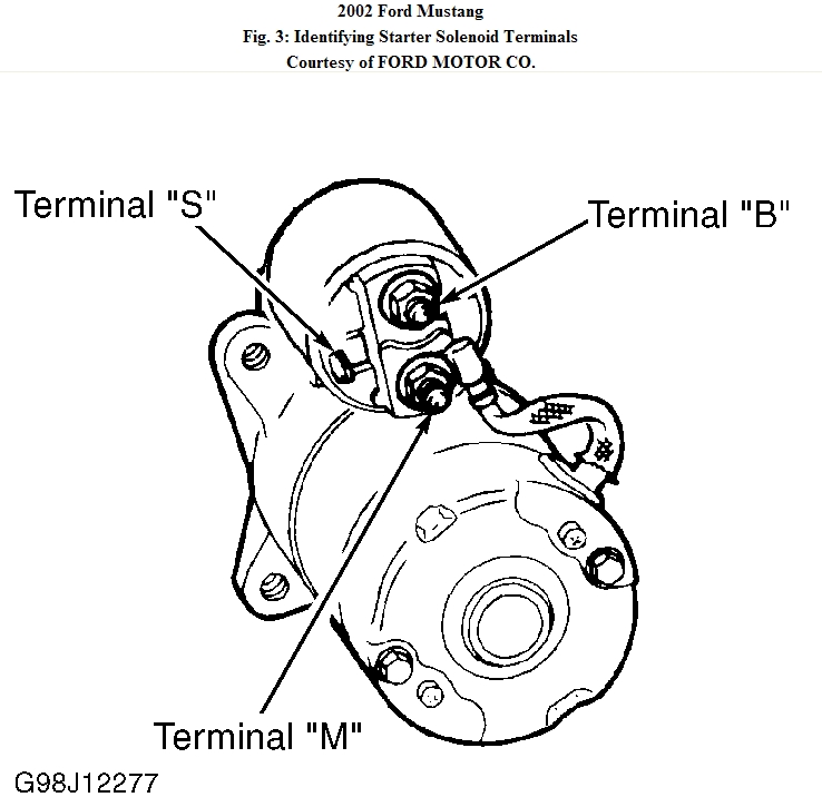
4. Measure voltage between starter motor battery cable terminal "B" and ground. See Fig. 3. If
battery voltage is present, go to next step. If battery voltage is not present, replace battery
positive cable and check for normal system operation.
Fig. 3: Identifying Starter Solenoid Terminals
Courtesy of FORD MOTOR CO.
5. Momentarily jump starter positive battery cable terminal "B" and start terminal
"S" (White/Pink wire). If starter motor operates properly, go to next step. If starter motor does
not operate properly, replace starter motor and check system for normal operation. See
STARTER MOTOR under REMOVAL & INSTALLATION.
6. Disconnect starter electrical connector terminal "S" (White/Pink wire). Place transmission in
Park or Neutral (A/T), or depress clutch pedal (M/T). Measure voltage between connector
terminal "S" (White/Pink wire) and ground with ignition switch in START position. If battery
voltage is not present, go to next step. If battery voltage is present, clean starter motor and
connector terminals. Check for loose or intermittent connection. Check system for normal
operation.
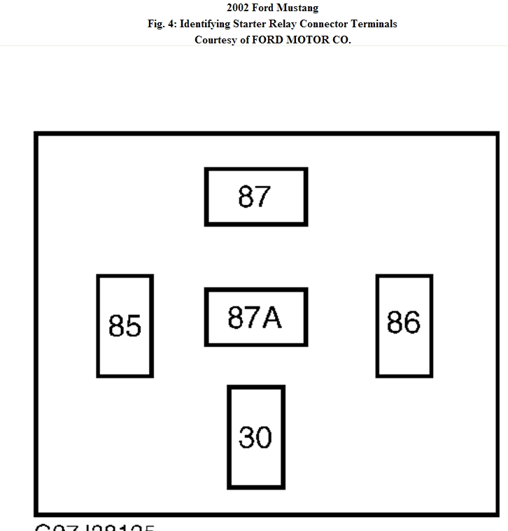
7. Turn ignition off. Remove starter relay from battery junction box. See Fig. 1. Place
transmission in Park or Neutral (A/T), or depress clutch pedal (M/T). Measure voltage between
starter relay connector terminal No. 85 (White/Pink wire) and ground with ignition switch in
START position. See Fig. 4. If battery voltage is present, go to next step. If battery voltage is
not present, go to step 12.
Fig. 4: Identifying Starter Relay Connector Terminals
Courtesy of FORD MOTOR CO.
8. Turn ignition off. Measure voltage between starter relay connector terminal No. 30 (Light
Green/Violet wire) and ground. If battery voltage is present, go to next step. If battery voltage
is not present, check fuse No. 3 (40-amp) in battery junction box. If fuse is okay, repair open in
Light Green/Purple wire between fuse and starter relay connector and check system for normal
operation. See WIRING DIAGRAMS.
9. Measure resistance between starter relay terminal No. 86 (Black wire) and ground. If resistance
is less than 5 ohms, go to next step. If resistance is 5 ohms or greater, repair open in Black wire
between starter relay connector and ground and check system for normal operation. See
10. Measure resistance between starter relay connector terminal No. 87 (Brown/Pink wire) and
ground. If resistance is greater than 10,000 ohms, go to next step. If resistance is 10,000 ohms
or less, repair short to ground in Brown/Pink wire and check system for normal operation. See
WIRING DIAGRAMS.
11. Measure resistance between starter relay connector terminal No. 87 (Brown/Pink wire) and
starter motor connector (White/Pink wire). If resistance is less than 5 ohms, install new starter
relay and check system for normal operation. If resistance is greater than 5 ohms, repair open
in Brown/Pink wire and/or White/Pink wire. See WIRING DIAGRAMS.
12. On M/T models, disconnect Clutch Pedal Position (CPP) switch connector. On A/T models,
disconnect CPP jumper connector located left of pedal assembly. To identify harness, see
WIRING DIAGRAMS. On all models, measure voltage between CPP connector (or jumper
connector) Red/Light Blue wire and ground with ignition switch in START position. If battery
voltage is present, go to step 14. If battery voltage is not present, go to next step.
13. Measure voltage between central junction box fuse No. 6 (20-amp) input side and ground with
ignition switch in START position. If battery voltage is not present, go to step 17. If battery
voltage is present, check fuse No. 6. If fuse is okay, repair Red/Light Blue wire between fuse
and CPP connector, (or CPP jumper connector), and check system for normal operation. See
WIRING DIAGRAMS.
14. Measure resistance in White/Pink wire between CPP connector (or CPP jumper connector) and
starter relay connector terminal No. 85. If resistance is less than 5 ohms, replace CPP switch
(or CPP jumper connector) and check system for normal operation. If resistance is greater than
5 ohms, go to next step (A/T) or repair wire between CPP switch and starter relay connector
(M/T). Check system for normal operation. See WIRING DIAGRAMS.
15. Disconnect Digital Transmission Range (DTR) sensor. Measure resistance between CPP
jumper harness connector (White/Pink wire) and DTR sensor connector terminal No. 10
(Red/Light Blue wire). See Fig. 5. If resistance is 5 ohms or less, go to next step. If resistance
is greater than 5 ohms, repair open White/Pink wire and/or Red/Light Blue wire between CPP
jumper connector and DTR sensor connector. Check system for normal operation. See
WIRING DIAGRAMS.
Fig. 5: Identifying Digital Transmission Range Sensor Harness Connector Terminals
Courtesy of FORD MOTOR CO.
16. Measure resistance of White/Pink wire between starter relay connector terminal No. 85 and
DTR sensor connector terminal No. 12. If resistance is greater than 5 ohms, repair open
White/Pink wire between starter relay connector and DTR sensor connector and check system
for normal operation. See WIRING DIAGRAMS. If resistance is 5 ohms or less, adjust DTR
sensor and recheck. See TRANSMISSION RANGE SENSOR under ADJUSTMENTS. If
resistance is still 5 ohms or less, replace DTR sensor and check system for normal operation.
17. Turn ignition off. Disconnect ignition switch harness connector. Measure voltage between
ignition switch harness connector terminal No. B4 and ground. See Fig. 6. If battery voltage is
present, go to next step. If battery voltage is not present, check fuse No. 3 (40-amp) in battery
junction box. If fuse is okay, repair Light Green/Purple wire between fuse No. 3 and ignition
switch harness connector. Check system for normal operation.
Fig. 6: Identifying Ignition Switch Harness Connector Terminals
Courtesy of FORD MOTOR CO.
18. Measure resistance between ignition switch harness connector terminal STA and central
junction box fuse No. 6 input terminal. See Fig. 6. If resistance is less than 5 ohms, replace
ignition switch and check system for normal operation. If resistance is 5 ohms or greater, repair
White/Pink wire between ignition switch and fuse. Check system for normal operation.
Images (Click to make bigger)
Sunday, February 13th, 2011 AT 4:50 PM