DIAGNOSIS & OVERHAUL - BORG WARNER 1354 -1994 Ford Ranger
Page 1 of 2
TESTING
ELECTRONIC SHIFT TRANSFER CASE
Circuit Protection
The battery feed circuit, through a circuit breaker, provides memory capability for electronic control module. Ignition RUN and ACC circuits, through a fuse, supply power for switches and electric shift
motor. The circuits supply power for illumination of instrument panel switches.
Control Module Self-Test
1.
To perform electronic control module self-test, remove 5-wire connector and 8-wire connector from module. Turn ignition switch to RUN position.
Activate self-test switch and note result. If LED flashes 4 times control module is okay. No illumination indicates a dead module and module must be replaced. A steady indicator light
indicates control module is inoperative and must be replaced. See Fig. 3.
2.
Fig. 3: Identifying Control Module Courtesy of FORD MOTOR CO.
Speed Sensor
Ensure speed sensor resistance is 225-275 ohms at module connection with vehicle stopped.
8-Wire Pigtail Connector Test
1.
With ignition off, unplug the 8-wire connector from module. Connect voltmeter between terminal No. 8 and ground. Battery voltage should be present. See Fig. 4.
Connect voltmeter between terminal No. 7 and ground. Turn ignition to RUN position. Battery voltage should be present.
2.
CAUTION: Disconnect battery cable before proceeding with ohmmeter
tests. Never connect an ohmmeter to powered circuit.
3.
Connect ohmmeter between terminal No. 6 and ground. Resistance should be less than 10 ohms. Connect ohmmeter between terminals No. 4 and 5 of connector. Resistance should be less than 10
ohms.
Connect ohmmeter between terminal No. 3 and ground. Resistance should be zero ohms. Resistance between terminal No. 2 and ground should be zero ohms.
4.
Fig. 4: 8-Wire Pigtail Connector & Function Chart Courtesy of FORD MOTOR CO.
1/1/2012
DIAGNOSIS & OVERHAUL - BORG WARNER 1354 -1994 Ford Ranger
Page 2 of 2
5-Wire Harness Connector Test
1.
Connect ohmmeter between terminals No. 1 and 2. Depress and hold 4WD switch; resistance should be less than 50 ohms. See Fig. 5.
Connect ohmmeter between terminals No. 1 and 3. Depress LOW RANGE switch. Resistance should be less than 50 ohms with switch depressed.
Connect jumper wire between terminal No. 4 and ground. Turn ignition switch to RUN position. Light in instrument panel and low range bar should illuminate. Turn ignition off and remove
jumper wire.
Connect jumper wire between terminal No. 5 and ground. Turn ignition to RUN position. The light in the instrument panel and 4WD bar should illuminate.
2.
3.
4.
Fig. 5: 5-Wire Harness Connector & Function Chart Courtesy of FORD MOTOR CO.
8-Wire Harness Connector Test
1.
Turn ignition off. Connect ohmmeter between terminal No. 1 and ground. On manual transmission, depress clutch pedal and observe ohmmeter. Resistance should be less than 50
ohms.
On automatic transmission, shift transmission into Neutral and observe ohmmeter. Resistance should be less than 50 ohms.
To check speed sensor continuity, measure resistance between terminals No. 2 and 3. See Fig. 6
There should be 200-350 ohms. Connect ohmmeter between terminal No. 8 and, in turn, terminals No. 4, 5, 6 and 9. Resistance should be as specified.
2.
.
3.
Fig. 6: 8-Wire Harness Connector & Function Chart Courtesy of FORD MOTOR CO.
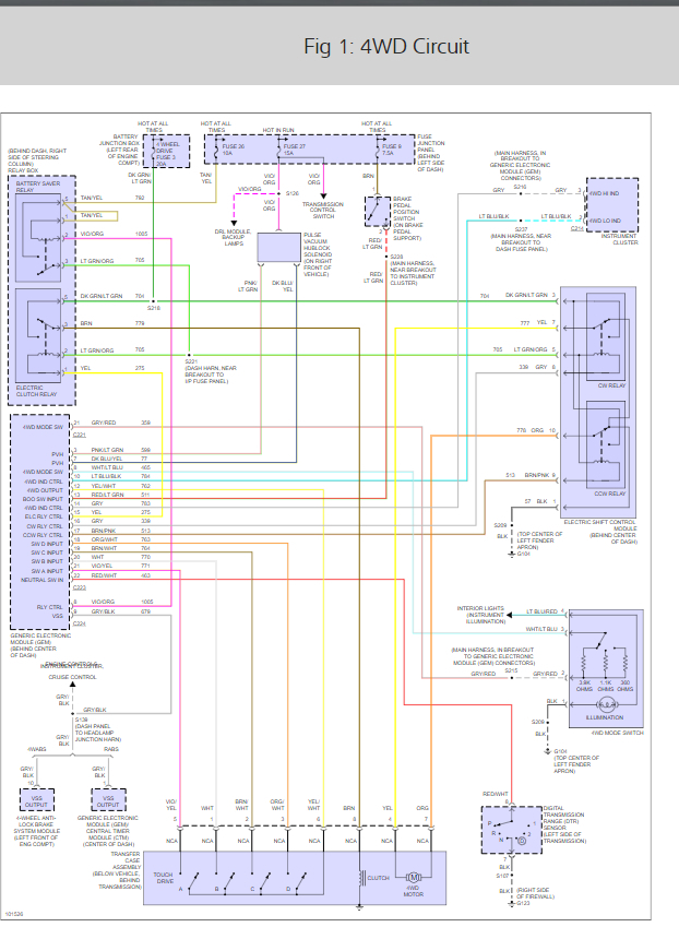
Electronic Transfer Case Feed
For functions of transfer case feed terminals, See Fig. 7. Ensure battery voltage is always present at terminals No. 1 and 4. Test remaining terminals for continuity to locations listed in function chart. See
WIRING DIAGRAMS.
Fig. 7: Identifying Electronic Transfer Case Feed Terminals Courtesy of FORD MOTOR CO.
SPONSORED LINKS
Friday, December 28th, 2018 AT 10:32 AM
(Merged)