Unless you replaced the TPS as an assembly with the throttle body, which would indicate it was calibrated, if not you would have to. It has slotted installation poits therefore it can be installed out of position.
Here are the test for the TPS and since you do not have the test harness, you may backprobe the relevant terminals if it requires testing but use only a fine sharp point or improvise by attaching a needle to the DVOM probes. Wire tapes for holding the needle onto the probes works well.
I would suggest paying attention to item # 3. It mentions replacing the TPS but you should try calibrating the TPS by loosening the holding screws and turning the TPS till it is at 0.5 V when throttle is fully closed.
Note : Ensure the TPS is seated correctly while installing. The tab on the TPS should slot in the the space in the throttle body, which starts when the holding bolts are out of position and TPS has to be turned with a little resistance when it is seated correctly.
CODE 7 - THROTTLE ANGLE SENSOR
1. Turn ignition off. Remove appropriate fuse for 10 seconds to reset ECU. Start engine. Verify if CHECK ENGINE light is flashing Code 7. If Code 7 is present, go to next step. If Code 7 is not present, problem is intermittent. Check connectors at throttle angle sensor and related circuits.
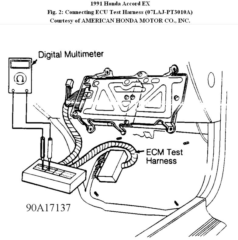
2. Turn ignition off. Disconnect 3-wire connector at throttle angle sensor. Turn ignition on. Measure voltage between Yellow/White (+) and Green/White (-) wires. If voltage is not about 5 volts, go to step 6). If voltage is about 5 volts, turn ignition off. Reconnect sensor connector. Connect ECU Test Harness between ECU and ECU connector. See
Fig. 2.
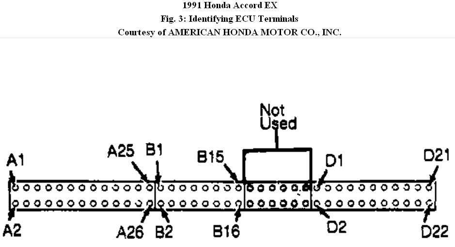
3. Turn ignition on. Measure voltage between positive terminal D11 and negative terminal D22. See Fig. 3. Voltage should be.5 volt at closed throttle and about 4.5 volts at wide open throttle. Transition between lower and upper voltage specification as throttle is depressed should be smooth.
4. If throttle sensor responds as indicated, substitute a known good ECU. If condition is corrected, replace original ECU. If sensor does not respond as indicated in step 3), replace throttle sensor or repair open or short in Red/Black wire between ECU terminal D11 and throttle sensor. On A/T models, go to step 5).
5. Disconnect 22-wire connector from A/T control unit. If throttle sensor now responds as indicated, replace A/T control unit. If throttle sensor does not respond as indicated, check for open or short in Red/Black wire between ECU terminal D11, throttle angle sensor and A/T control unit.
6. If voltage reading between Yellow/White (+) and Green/White (-) wires in step 2) is not about 5 volts, measure voltage between ground and Yellow/White wire terminal. If voltage is now about 5 volts, repair open in Green/White wire between ECU terminal D22 and throttle sensor. If reading is not about 5 volts, turn ignition off.
7. Connect ECU Test Harness between ECU and ECU connector. Turn ignition on. Measure voltage between terminal D20 and terminal D22. If voltage is about 5 volts, repair open Yellow/White wire between ECU terminal D20 and throttle sensor. If reading is not about 5 volts, substitute a known good ECU. If condition is corrected, replace original ECU.
Images (Click to make bigger)
Monday, January 3rd, 2011 AT 8:33 PM