The running light circuit is controlled electrically through a basic switch, BCM (body control module) or a LCM (lighting control module). These computer controllers are designed to warn about a bulb failure by illuminating a warning light on the dash. In older cars the headlight switch performed the actual power distribution to the headlights instead of using a relay and computer. American car's running lights are integrated into the blinker bulbs, while Japanese and European cars have separate lighting systems. Vehicles that have towing capabilities use a separate wiring system to power trailer lights, which are protected by additional fuses located in power distribution center. The rear license plate bulb is also illuminated when the running lights are on. Some systems are equipped with a timer that allows the lights to stay on for a predetermined amount of time after the driver has exited the vehicle.
Common Problems
- Tail light bulbs are replaced with incorrect bulb causing improper operation.
- If tail lights stay on continuously, the headlight/tail light switch or BCM has failed.
Let's Jump In!
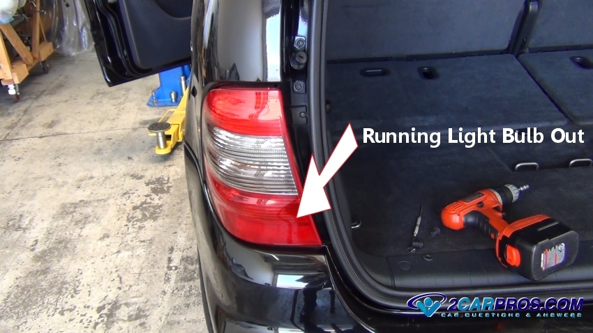
Identify the light or lights that are non operational. If one tail light bulb
has failed, the problem is probably the bulb itself or a bad connection, if all
lights are non-operational, follow down the guide to Step 5.
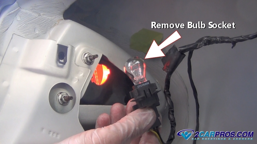
Remove bulb socket to expose the bulb for inspection, gently grasp the bulb and
pull or push down and twist counterclockwise to remove, some bulbs are accessible
by removing the lens itself while other require the removal of a plastic panel.
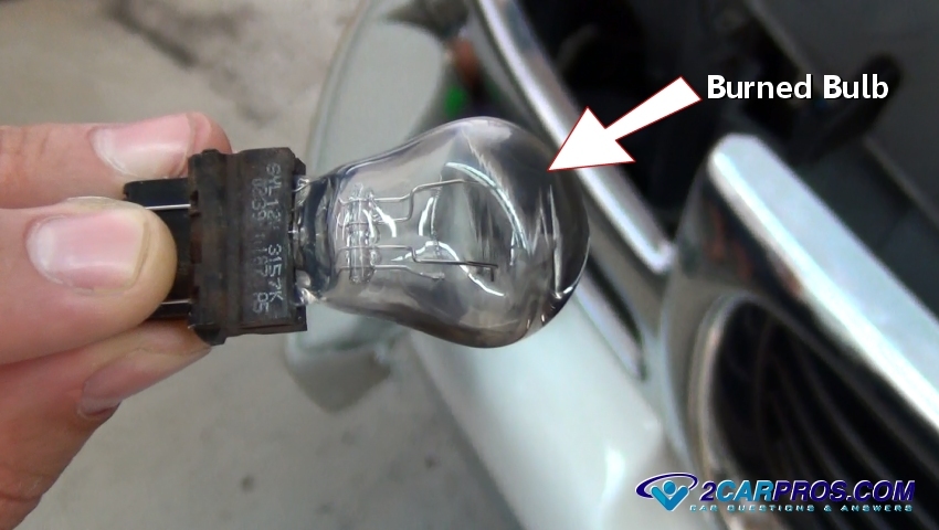
Remove the bulb and inspect, check for any burned color or white with blue smoke
inside the bulb which is an indication of failure.
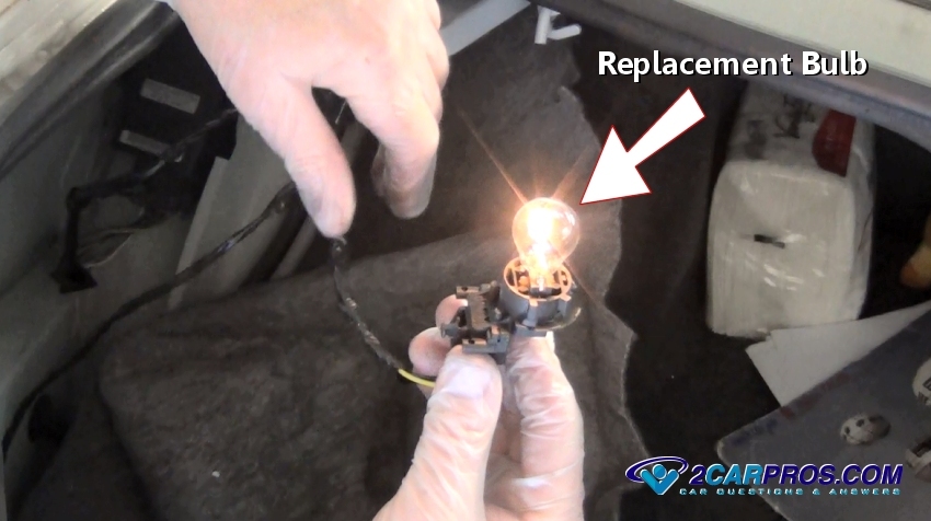
Replace the bulb with new and recheck before re-installation.
Watch the Video!
Please watch this video of the job being done, then continue down the guide to glean additional helpful information.
If a new bulb still doesn't operate,
use a grounded testing
light to help test power feeds to the bulb.
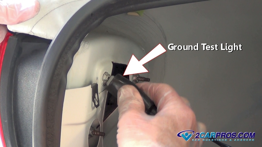
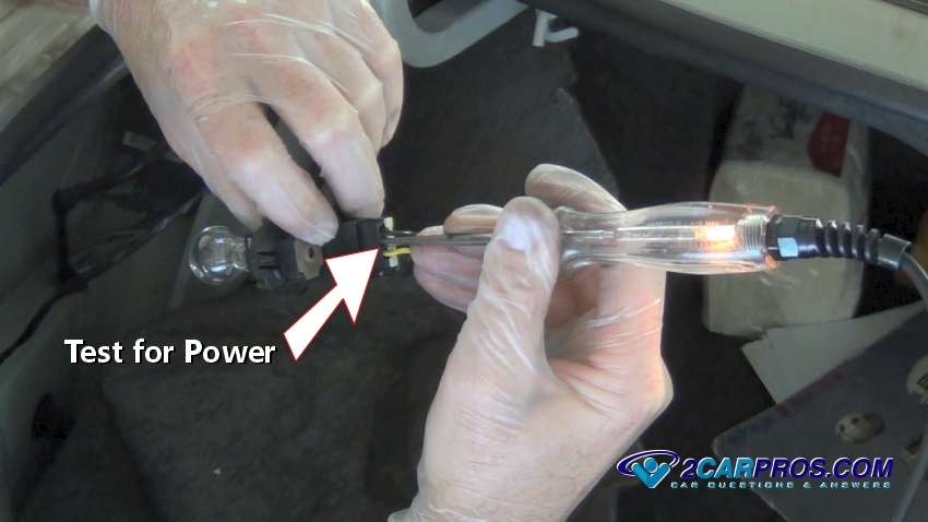
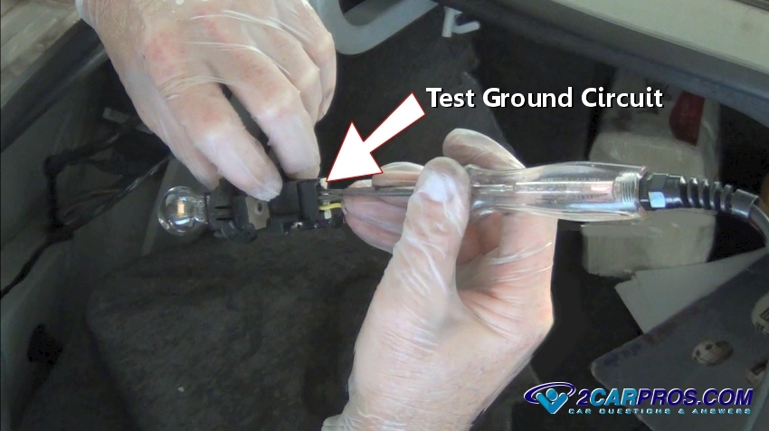
With the bulb removed (optional) and while the running lights are on, use a grounded
test light to test the inner contacts of the bulb socket or wire connectors. Be
careful not to touch the test light lead to the outer socket ring or to ground for
this will cause a short circuit and fuse failure.
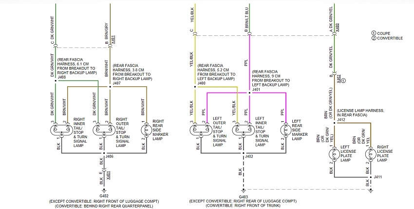
A diagram will facilitate repairs but is not needed for this test.
ask the 2CarPros community to obtain a diagram, its free.
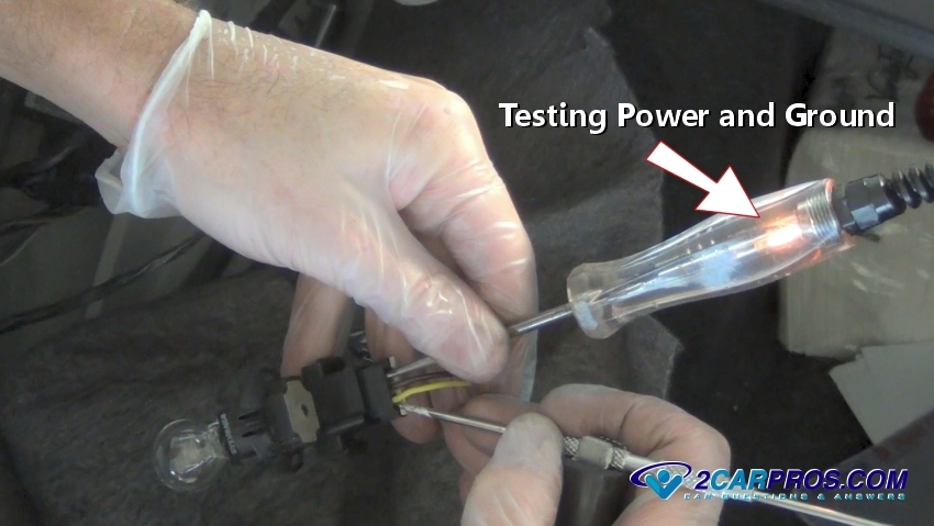
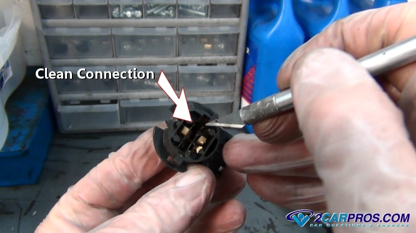
After confirming power is present at the socket, attach a pick or other pointy
metal object to the test light clip, insert both probe and pick into the ground
and power terminals or wiring, this test confirms power and ground at the socket.
Using an Exacto blade or sandpaper, scrape clean the terminal connections that
are inhibiting the electrical flow. Lighting sockets are subject to heat and can
melt plastic and cause corrosion which promotes bulb operation failure, in severe
cases the socket will need to be replaced.
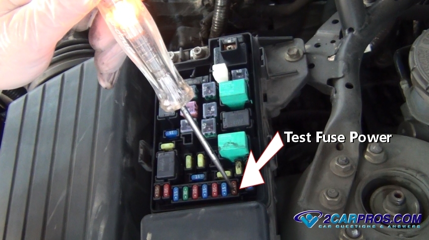
If all running or tail lights are not working, a fuse is used to protect the
lighting system from overload and short circuits, anytime more than one light bulb
is out, the fuse is the first place
to check, these fuses are located in the power distribution center (PDC).
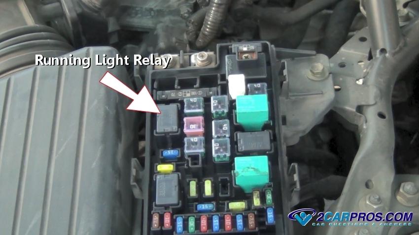
A tail light control relay is used to help shoulder the electrical draw many
bulbs can cause on a single circuit, this task is carried out by the BCM (body control
module). The headlight/running light switch is used as the trigger circuit which
sends a signal to activate the relay.
Test the relay, because when this relay fails, it will hinder the operation
of the running lights.
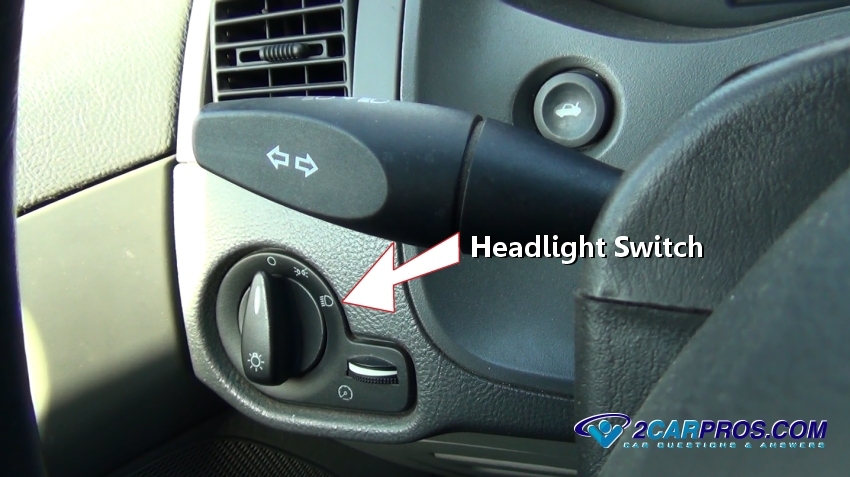
Next, remove the headlight switch to probe harness wires, the
test light must be connected
to positive power such as the battery which is needed to test ground circuit
connections. Observe the test light while operating the switch, the light should
follow the switch operation. On older cars, the switch controls headlight and tail
light power, instead of grounding BCM triggers. For these systems use a grounded
test light and test for twelve volts at the rear of the headlight switch connector
(removed) on one or two of the terminals or wires. If no power is confirmed, repair
the fuse holder or the power feed (maxifuse - fusible) from the fuse panel to the
switch. If power is confirmed at the rear of the switch, turn the switch to the
on position and test the remaining terminals (or wires), power should be present
at the remaining terminals.
A dim light is caused by a poor ground circuit which causes the electrical flow
to back feed resulting in higher than usual resistance. While the tail light bulb
is installed, touch a grounded test light to the outer ring or ground wire of the
bulb socket. If the bulb brightness increases, the bulb socket ground has gone open
and must be cleaned or repaired-replaced.
Flickering or flashing lights occur because a power or ground source is being disconnected momentarily and then reconnected. Common causes for this condition is a loose fitting bulb inside the socket. To test for this condition expose the tail light bulb in question. Next, switch the tail lights on and move the bulb around slightly in the socket. If the bulb flickers tighten the socket or replace the bulb/socket to regain proper operation. If the complete system flickers (all bulbs flicker) wiggle the tail light fuse, relay and associated wiring at the headlight/tail light switch.
Questions?
Our certified technicians are ready to answer running or tail light not working questions for free. We hope you saved money and learned from this guide. We are creating a full set of car repair guides. Please subscribe to our 2CarPros YouTube channel and check back often for new videos which are uploaded regularly.