Welcome to 2CarPros.
It has been awhile since I worked on one. However, if I recall correctly, it's 32mm. Try that.
Also, here are the directions for removal and replacement. The attached pics correlate with the directions.
______________________________________
2001 Chrysler Concorde V6-3.2L VIN J
Axle Shaft, Constant Velocity Type
Vehicle Transmission and Drivetrain Drive Axles, Bearings and Joints Axle Shaft Assembly Axle Shaft Service and Repair Procedures Axle Shaft, Constant Velocity Type
AXLE SHAFT, CONSTANT VELOCITY TYPE
REMOVAL
(1)Raise vehicle on jackstands or centered on a frame contact type hoist.
(2)Remove the front wheel and tire assembly from the vehicle.
Pic 1
(3)Remove the front caliper assembly from the front steering knuckle assembly (Fig. 3).
Pic 2
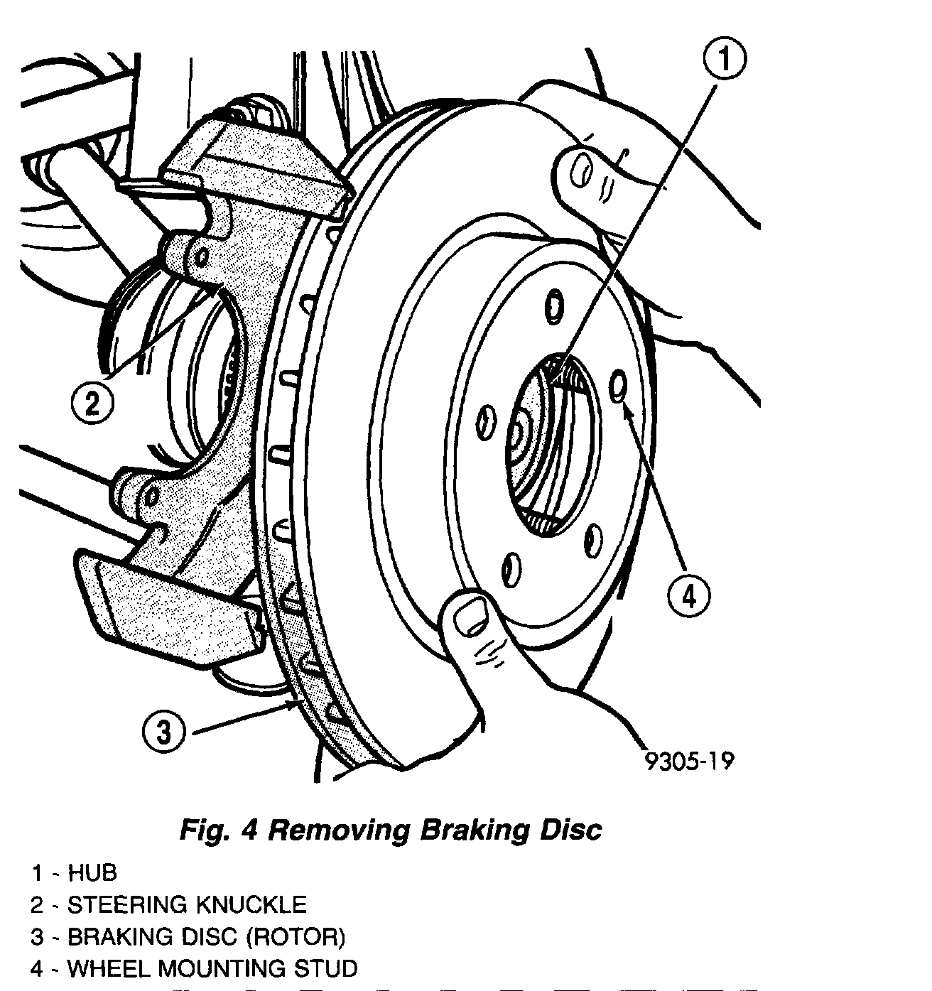
(4)Remove front braking disk (rotor) from hub, by pulling it straight off wheel mounting studs (Fig. 4).
Pic 3
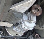
(5)Remove the speed sensor cable routing bracket from the strut assembly (Fig. 5).
Pic 4
(6)Remove the hub and bearing-to-stub axle retaining nut (Fig. 6).
Pic 5
(7)Dislodge inner tripod joint from stub shaft retaining snap ring on transaxle assembly (Fig. 7). Inner tripod joint is dislodged from stub shaft retaining snap ring, by inserting a pry bar between transaxle case and inner tripod joint and prying on tripod joint. Only disengage the inner tripod joint from the retaining snap ring. Do not attempt to remove the inner tripod joint from the transmission stub shaft at this time.
CAUTION: The strut assembly to steering knuckle bolts are serrated where they go through strut assembly and steering knuckle. When removing bolts, turn nuts off bolts. DO NOT TURN BOLTS IN STEERING KNUCKLE. If bolts are turned, damage to steering knuckle will result.
Pic 6
(8)Remove the strut assembly to steering knuckle attaching bolts (Fig. 8).
Pic 7
(9)Remove the top of the steering knuckle from the strut assembly.
CAUTION: When removing outer C/V joint from hub and bearing assembly, do not allow the flinger disk (Fig. 9) on hub and bearing assembly to become damaged. Damage to the flinger disk will cause dirt and water intrusion into bearing. Premature bearing failure will result.
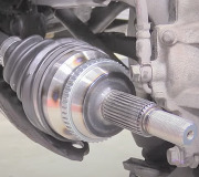
(10)Hold outer C/V joint assembly with one hand. Grasp steering knuckle with other and rotate it out and to the rear of the vehicle, until outer C/V joint clears hub and bearing assembly (Fig. 9).
Pic 8
(11)Remove driveshaft inner tripod joint from transaxle stub shaft. When removing driveshaft, do not pull on interconnecting shaft to remove inner tripod joint from stub shaft. Removal in this manner will separate the spider assembly from the tripod joint housing. Grasp inner tripod joint (Fig. 10) and interconnecting shaft and pull on both pieces at the same time.
INSTALLATION
CAUTION: The inboard tripod joint retaining circlip and O-ring seal (Fig. 11) on the transaxle stub shaft, are not re-usable. Whenever the inboard tripod joint is removed from the stub shaft, the retaining circlip and O-ring seal MUST BE REPLACED. The retaining circlip and O-ring seal is included in all service kits requiring removal of the inboard tripod joint from the stub shaft.
Pic 9
(1)Replace O-ring seal and tripod joint retaining circlip (Fig. 11) on the transaxle stub shaft.
Pic 10
(2)Evenly apply a bead of grease, such as Mopar Multi-Purpose Lubricant or an equivalent, around spline of inner tripod joint (Fig. 12) where the O-ring seats against tripod joint. This will spread grease onto stub shaft during tripod joint installation preventing corrosion and help to seal the O-ring.
Pic 11
(3)Install driveshaft through hole in splash shield. Grasp inner tripod joint in one hand and interconnecting shaft in the other. Align inner tripod joint spline with stub shaft spline on transaxle (Fig. 13). Use a rocking motion with the inner tripod joint, to get it past the circlip on the transaxle stub shaft.
(4)Continue pushing tripod joint onto transaxle stub shaft until it stops moving. The O-ring seal on the stub should not be visible when inner tripod joint is fully installed on stub shaft. To check that inner tripod joint retaining circlip is locked into tripod joint, grasp inner tripod joint and pull on it by hand. If circlip is locked into tripod joint, tripod joint will not move on stub shaft.
CAUTION: When installing outer C/V joint into the hub and bearing assembly, do not allow the flinger disk on hub and bearing assembly to become damaged. Damage to the flinger disk can cause dirt and water intrusion into bearing and premature bearing failure.
Pic 12
(5)Hold outer C/V joint assembly with one hand. Grasp steering knuckle with other hand and rotate it out and to the rear of the vehicle. Install outer C/V joint into the hub and bearing assembly (Fig. 14).
(6)Install the top of the steering knuckle into the strut assembly. Align the steering knuckle to strut assembly mounting holes.
CAUTION: The strut assembly to steering knuckle bolts are serrated where they go through strut assembly and steering knuckle. When installing bolts, turn nuts onto bolts. DO NOT TURN BOLTS IN STEERING KNUCKLE. If bolts are turned, damage to steering knuckle will result.
Pic 13
(7)Install the strut assembly to steering knuckle attaching bolts. Install nuts on attaching bolts (Fig. 15). Tighten the strut assembly to steering knuckle bolt nuts to 210 Nm (155 ft. Lbs.). TURN NUTS ON BOLTS. DO NOT TURN BOLTS.
CAUTION: The hub and bearing assembly to stub shaft retaining nut is a prevailing torque nut and can not be refused. A NEW retaining nut MUST be used when assembled.
Pic 14
(8)Install a NEW retaining nut (Fig. 16). Tighten, but do not torque the hub nut at this time.
(9)Install speed sensor cable routing bracket on front strut assembly. Install and securely tighten routing bracket screw.
Pic 15
(10)Install the braking disk on the hub and bearing assembly (Fig. 17).
Pic 16
(11)Install front brake caliper over braking disc and align with caliper mounting holes on steering knuckle (Fig. 18). Install the caliper to steering knuckle bolts. Tighten bolts to 22 Nm (192 inch lbs.).
Pic 17
(12)Install wheel and tire assembly on vehicle. Tighten the wheel mounting stud nuts in proper sequence (Fig. 19), until all nuts are tightened to half specification. Then repeat the tightening sequence to the full specified torque of 135 Nm (100 ft. Lbs.).
(13)Lower vehicle to the ground.
CAUTION: When tightening hub and bearing assembly to stub shaft retaining nut, do not exceed the maximum torque of 142 Nm (105 ft. Lbs.). If the maximum torque is exceeded this may result in a failure of the driveshaft.
Pic 18
(14)Apply the vehicle's brakes to keep vehicle from moving. Tighten the NEW stub shaft to hub and bearing assembly retaining nut to 142 Nm (105 ft. Lbs.) (Fig. 20).
_____________________________________________
Let me know if this helps or if you have other questions.
Take care,
Joe
Images (Click to make bigger)
SPONSORED LINKS
Friday, October 18th, 2019 AT 10:16 PM