Engine revs

Tiny
MERLIN2021
  • MECHANIC
  • 17,250 POSTS
E Bay. How did it run B4 you replace the distributor?
I lean more towards that part than any other. Set everything on #1, mark the manifold where the pointer for #1 is in the distrib, and remove it, go to the parts store you bought it at, and have them test it.
Was this
answer
helpful?
Yes
No
Sunday, October 22nd, 2017 AT 1:36 PM (Merged)
Tiny
KIRKH34
  • MEMBER
  • 20 POSTS
It ran fine before my water pump went out. Then I just couldn't get anything started again but I did get that CID ID failure so I figured the ignition module inside the disty was bad. I still couldn't get it started though until I moved a motor mount ground, at least it seemed like when I moved the ground it finally started but barely. Before that I didn't know the cause of it not starting. There were many factors including the timing of the engine and the old disty and the ground. I finally got the timing of the engine right but I needed a cam locking tool that I didn't have before, then after the disty and after the ground moved it started, I also noticed a couple days ago while cranking I saw a huge spark come from the negative battery terminal. Could my grounds still be bad? Is there a way to test if things aren't being grounded fully with a muilti-meter?
Was this
answer
helpful?
Yes
No
Sunday, October 22nd, 2017 AT 1:36 PM (Merged)
Tiny
MERLIN2021
  • MECHANIC
  • 17,250 POSTS
If you are getting sparks at the battery, inspect the cables, Both pos and neg, Real important on these newer cars with computer controls, if the PCM is not grounded properly, or battery voltage ois below 10 volts, the PCM will NOT operate correctly.
https://www.2carpros.com/how_to/how_to_test_alternator.htm
https://www.2carpros.com/how_to/battery.htm
I am still of the opinion that it's distributor related. Or ground fualt related NOW!
Was this
answer
helpful?
Yes
No
Sunday, October 22nd, 2017 AT 1:36 PM (Merged)
Tiny
KIRKH34
  • MEMBER
  • 20 POSTS
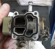
I have cleared all my codes by disconnecting the battery for a long period of time, I still get a 121 TPS out of range code. I thought I was getting this code because I had unplugged it but it has come back, I have tested this according to the chilton manual.

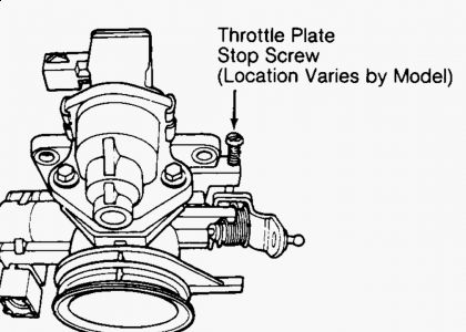
1. Insert 0.1 mm feeler gauge between stop lever and throttle stop screw, verify there is continuity between terminals IDL and E
-yes

2. Replace feeler gauge w/ 0.7 mm and verify there is NO continuity
- there IS still continuity according to my meter

3. Then open throttle wide and verify there is still no continuity
-there still IS continuity, about 2-3 k ohms

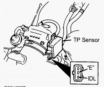
4. Insert 0.1 mm feeler gauge between stop lever and throttle stop screw, verify there is NO continuity between terminals POW and E
-there still IS continuity.

5. Replace feeler gauge w/ 0.7 mm and verify there is NO continuity
-still is continuity.

6. Open throttle wide and verify there is continuity between POW and E
-yes

basically, no matter what terminals I am testing. I am getting continuity all the time. A smooth flow of numbers rising everytime I open the throttle, the wider the throttle, the higher the numbers, I have good voltage as I mentioned earlier in the post, does this mean my tps is bad? I heard there is a way to set the TPS by the fan method, by turning it until the fans kick on in diagnostic mode then turning it back a little til they shut off. No matter how far I turn the tps the fans do not kick on. Are there any other ways I can test this to be sure this is the problem? They are over 100 dollars I can't really afford to just replace it
Was this
answer
helpful?
Yes
No
Sunday, October 22nd, 2017 AT 1:36 PM (Merged)
Tiny
MERLIN2021
  • MECHANIC
  • 17,250 POSTS
I show 2.0 is not adjustable, throttle body assembly is replaced!
THROTTLE POSITION (TP) SENSOR Except 1.8L & 2.0L A/T TP sensor is not adjustable. Ensure TP sensor is properly installed. See THROTTLE POSITION (TP) SENSOR under FUEL SYSTEM in N - REMOVE/INSTALL/OHAUL article in the ENGINE PERFORMANCE Section. If additional test procedures are required, see G - EEC-IV TESTS W/ CODES article in the ENGINE PERFORMANCE Section. 1.8L A/T 1. Turn ignition off. Remove TP sensor connector. Loosen TP sensor mounting screws. Install a 0.010" (.25 mm) feeler gauge between throttle plate stop screw and throttle lever. See Fig. 5 . Connect ohmmeter leads to terminals "E" and IDL. See Fig. 7 . 2. Rotate TP sensor clockwise about 30 degrees. Rotate TP sensor counterclockwise until continuity is present. 3. Remove 0.010" (.25 mm) feeler gauge and install a .016" (.40 mm) feeler gauge between throttle plate stop screw and throttle lever. Continuity should not be present. If continuity is present, repeat steps 1) and 2). 4. If continuity is not present, tighten TP sensor mounting screws. Cycle throttle to wide open position several times. Connect ohmmeter leads to TP sensor terminals "E" and VT. Resistance should be about 5000 ohms. Replace TP sensor if continuity is not as specified. Fig. 7: Identifying TP Sensor Connector Terminals (1.8L A/T) Courtesy of FORD MOTOR CO. 1.8L M/T 1. Turn ignition off. Remove TP sensor connector. Install a 0.016" (.40 mm) feeler gauge between throttle plate stop screw and throttle lever. See Fig. 5 . 2. Connect ohmmeter leads to terminals "E" and IDL. See Fig. 8 . Loosen TP sensor mounting screws. Rotate TP sensor clockwise about 30 degrees. Rotate TP sensor counterclockwise until continuity is present. 3. Remove 0.016" (.40 mm) feeler gauge and install a .027" (.70 mm) feeler gauge between throttle plate stop screw and throttle lever. Continuity should not be present. If continuity is present, repeat steps 1) and 2). If continuity is still present, replace TP sensor. Fig. 8: Identifying TP Sensor Connector Terminals (1.8L M/T) Courtesy of FORD MOTOR CO. 2.0L A/T TP sensor is not adjustable. If TP sensor calibration falls out of adjustment, replace throttle body assembly.


https://www.2carpros.com/forum/automotive_pictures/62217_1_23.jpg


https://www.2carpros.com/forum/automotive_pictures/62217_2_23.jpg


https://www.2carpros.com/forum/automotive_pictures/62217_3_24.jpg


https://www.2carpros.com/forum/automotive_pictures/62217_TPS_5.jpg


Use the color of the wires at the sensor to test them at the PCM, no need to buy a "breakout box"
Was this
answer
helpful?
Yes
No
Sunday, October 22nd, 2017 AT 1:36 PM (Merged)
Tiny
KIRKH34
  • MEMBER
  • 20 POSTS
Well, no matter what I do, I can't get it to where it doesn't have continuity. It always has continuity, so maybe it's bad
Was this
answer
helpful?
Yes
No
Sunday, October 22nd, 2017 AT 1:36 PM (Merged)
Tiny
MERLIN2021
  • MECHANIC
  • 17,250 POSTS
You can test for proper voltage, I posted the chart. Closed it should be 0.61 volts wide open 4.5 volts, needle should move smoothly, no jerking.
Was this
answer
helpful?
Yes
No
Sunday, October 22nd, 2017 AT 1:36 PM (Merged)
Tiny
COLT COLEMAN
  • MEMBER
  • 17 POSTS
Here's a question what did you clean maf sensor with? You could have messed it up
Was this
answer
helpful?
Yes
No
Sunday, October 22nd, 2017 AT 1:36 PM (Merged)

Please login or register to post a reply.

Sponsored links