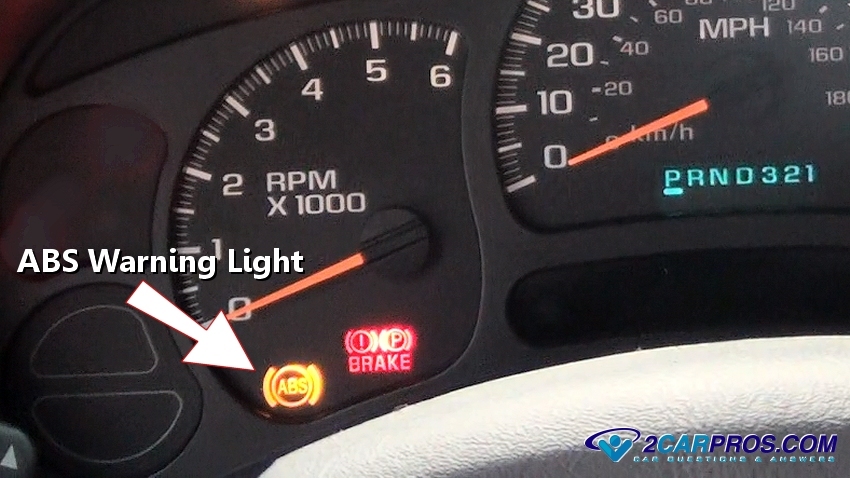
An ABS (antilock brake system) and traction control systems are closely related, this is why when one system has a problem, so does the other while illuminating both warning lights at the same time. If the ABS or traction control warning lights are on the system is disabled compromising the safety of the vehicle. While all car manufactures seem to agree on the brake portion of the safety system, ABS, each of them have a different name for the traction control portion:
- Toyota - Vehicle Stability Control (VSC)
- Ford - AdvanceTrac
- General Motors (Chevrolet, GMC, Cadillac, etc.) - StabiliTrak
- Fiat Chrysler Automobiles (Dodge, Jeep, Chrysler) - Electronic Stability Control (ESC)
- Honda - Vehicle Stability Assist (VSA)
- Nissan - Vehicle Dynamic Control (VDC)
- Hyundai - Electronic Stability Control (ESC)
- Kia - Electronic Stability Control (ESC)
- BMW - Dynamic Stability Control (DSC)
- Mercedes-Benz - Electronic Stability Program (ESP)
- Volkswagen - Electronic Stability Control (ESC)
- Audi - Electronic Stability Control (ESC)
- Porsche - Porsche Stability Management (PSM)
- Mazda - Dynamic Stability Control (DSC)
- Subaru - Vehicle Dynamics Control (VDC)
- Volvo - Dynamic Stability Traction Control (DSTC)
Introduction
The ABS and traction control system work hand in hand as both are designed to keep the car under control in an emergency situation while protecting against loss of vehicle control for the driver. This is done by limiting the rotation of a tire that has lost traction with the highway (braking), or slow down a tire that is slipping (acceleration). The components to achieve such systems have changed and been updated over the years by becoming more compact and efficient. By using a series of sensors the ABS control module and traction control computer data is analyzed and adjustments are made to steady the vehicle in motion.
How It Works
Once these safety systems have detected a problem they jump into action by reducing the throttle bore opening to slow down the engine, also the system will pulse the brake pedal to limit or add pressure to a particular wheels using the brake hydraulic system brake. This is done with the help of a Yaw Rate Sensor that uses a gyroscopic to help predict the inertia direction of the vehicle with four wheel speed rotational sensors, one at each wheel.
These system have become so accurate that most manufacturers have substituted the transmission output shaft speed sensor (VSS - vehicle speed sensor) for the collective data of each wheel speed sensor.
Most ABS brake systems are a "real time system", so when a trouble code is triggered, and the repairs made, the code will clear itself within a few yards of driving.
During an ABS or Traction control event the brake pedal will vibrate as the system kicks into action, this is normal.
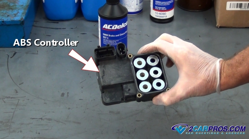
The ABS and traction control system utilizes an electronic control unit, which is comprised of solenoids which together with the valve module can modulate or increase brake line pressure to a particular wheel. This will allow tire rotation when skidding, or add pressure to stop the tire from slipping (excessive acceleration).
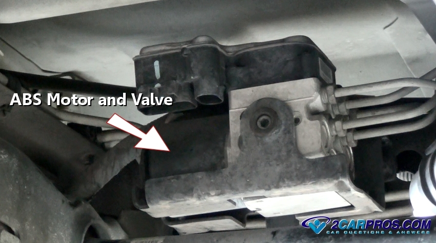
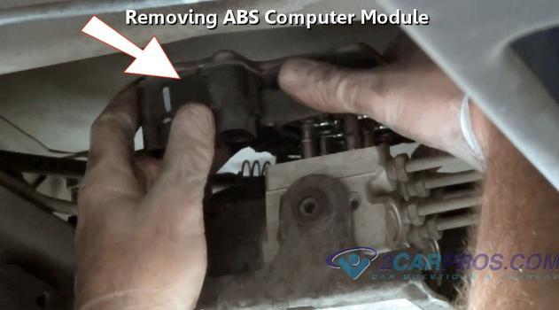
Usually the ABS and traction control unit will be mounted to the motor and valve assembly, either under the hood or on the frame rail depending on the manufacturer. The valve block is where the brake fluid enters from the brake master cylinder and then exits to each wheel individually.
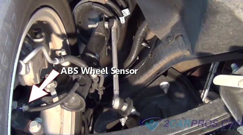
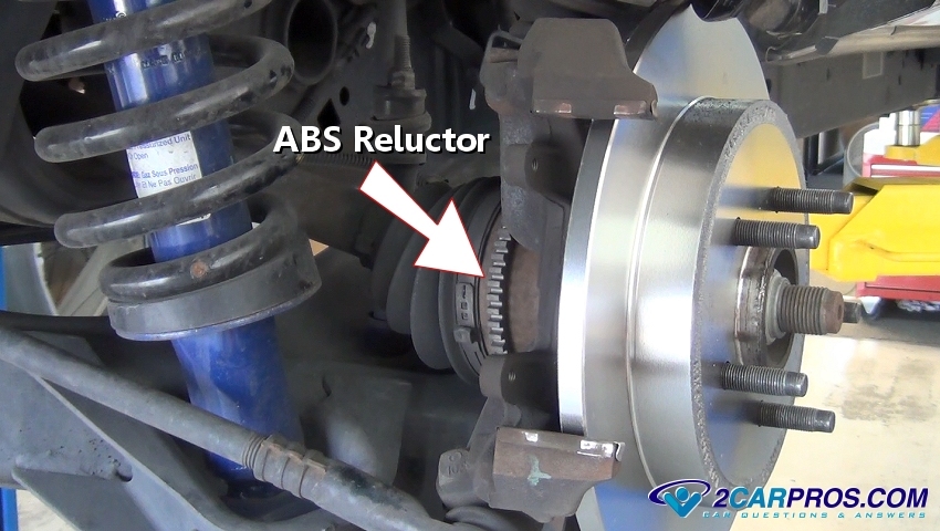
Wheel rotational speed sensors are used at each wheel, though some systems only use one rear wheel sensor that is mounted to the center of the rear differential. These sensors are located near the center of the rotating mass to give feedback data to the ABS/Traction Control module. Also, these sensors can be integrated into the wheel bearing hubs, when these bearing go out it can cause an ABS/Traction Control warning light.
Here is a ABS/Traction Control system wheel speed sensor reluctor which has a number of teeth and is where the wheel speed sensor picks up the pulse signal which is reported to the main ABS/Traction Control unit where it is analyzed hundreds of times per second. These reluctors can be mounted to the CV axle or inside the bearing hub.
Conclusion
The lives these safety systems have saved is un-measurable, not to mention the property damage that has been avoided. To keep these safety system working correctly be sure to service the brake system regularly which includes brake fluid bleed and flush while checking the brake pads for wear.
Credits
This guide knowledge base was created by the 2CarPros Team, and by Ken Lavacot: Automobile repair shop owner and certified master automobile technician of over 30 years. If you have question or need help please ask one of our experts we are happy to help. Please visit our 2CarPros YouTube Channel.
Article published 2024-04-17
ABS Module Replacement Video
Bleed your ABS Brake System Correctly Video